
The global transition towards renewable energy sources has created an unprecedented demand for efficient and reliable energy storage solutions. Electrochemical energy storage, particularly lithium-ion battery technology, stands as a cornerstone for modern grid management, enabling the balancing of supply and demand, enhancing power quality, and facilitating the large-scale integration of intermittent renewable sources like solar and wind. The cell energy storage system has thus evolved from a supplementary technology to a critical infrastructure component. Among various chemistries, Lithium Iron Phosphate (LFP) batteries have garnered significant attention for stationary storage due to their inherent safety, long cycle life, and cost-effectiveness. However, as the scale of deployment expands, reducing the Levelized Cost of Storage (LCOS) remains a paramount challenge. A substantial portion of a cell energy storage system‘s cost is attributed to the battery cells and the associated Balance of Plant (BOP). One direct pathway to reduce system cost and complexity is to increase the energy content per individual battery cell, thereby reducing the number of cells, connectors, and management units required for a given system capacity.
This drive for cost reduction has propelled the development of large-format cells, with capacities escalating from the prevalent 280 Ah to 430 Ah and beyond. Yet, scaling cell capacity introduces significant technical challenges, primarily concerning safety and performance uniformity. Larger cells contain more active material and electrolyte, which, in a failure event, could release more energy. Concerns regarding thermal runaway propagation, internal short circuits, and mechanical stability become magnified. Therefore, simply enlarging the dimensions of a conventional cell design is insufficient. Innovations in internal architecture and component engineering are essential to ensure that increased capacity does not come at the expense of safety or longevity. This study investigates a holistic design approach for a 430 Ah LFP battery, focusing on structural and material-level optimizations to achieve superior safety and electrochemical performance compared to a standard 280 Ah benchmark, providing a viable blueprint for the next generation of high-capacity cell energy storage system units.
1. Experimental Methodology: Cell Design and Fabrication
The core of this research involves a comparative analysis between a self-developed 430 Ah prismatic LFP cell and a commercially typical 280 Ah prismatic LFP cell. The fundamental electrode chemistries were kept consistent to isolate the effects of mechanical design and component choice. The positive electrode utilized high-purity LiFePO₄ as the active material, blended with conductive carbon black and carbon nanotubes (CNTs) using a dual-planetary mixer. The slurry, using PVDF binder in NMP solvent, was coated onto a 13 μm aluminum foil, calendered, and cut to specific dimensions. The negative electrode consisted of artificial graphite mixed with conductive additive (SP-C65), CMC, and SBR binder, coated onto a 6 μm copper foil and similarly processed.
The critical differentiators lie in the internal structure and separator selection:
- 430 Ah Cell (Laminated Structure): Employed a Z-folded or laminated stack design. The electrodes and separator are assembled as flat, discrete layers. The separator was a composite, starting with a 9 μm thick polyethylene (PE) base membrane (porosity 45%). A 3 μm ceramic coating (boehmite, D50: 0.5-1 μm) was applied for thermal stability, followed by a 2 μm layer of PVDF-based adhesive on one side. The final separator thickness was 14 μm. The cell dimensions were 530 mm × 218 mm × 32 mm, resulting in a large, thin “large-flat” format. The nominal capacity was 430 Ah, with a designed N/P ratio of 1.15.
- 280 Ah Cell (Wound Structure): Utilized a conventional wound jellyroll design. The electrode sheets and separator are wound together around a central mandrel. The separator was a 12 μm ceramic-coated membrane, using the same 9 μm PE base with a 3 μm ceramic layer but without the PVDF adhesive coating. The cell dimensions were 173 mm × 207 mm × 71 mm, making it considerably thicker. The nominal capacity was 280 Ah, with an identical N/P ratio of 1.15.
Both cell types used the same electrolyte formulation: 1 mol/L LiPF₆ in EC:DMC:DEC (2:5:3 by volume). This controlled comparison allows for a direct assessment of how the laminated structure and adhesive-coated separator influence cell behavior.
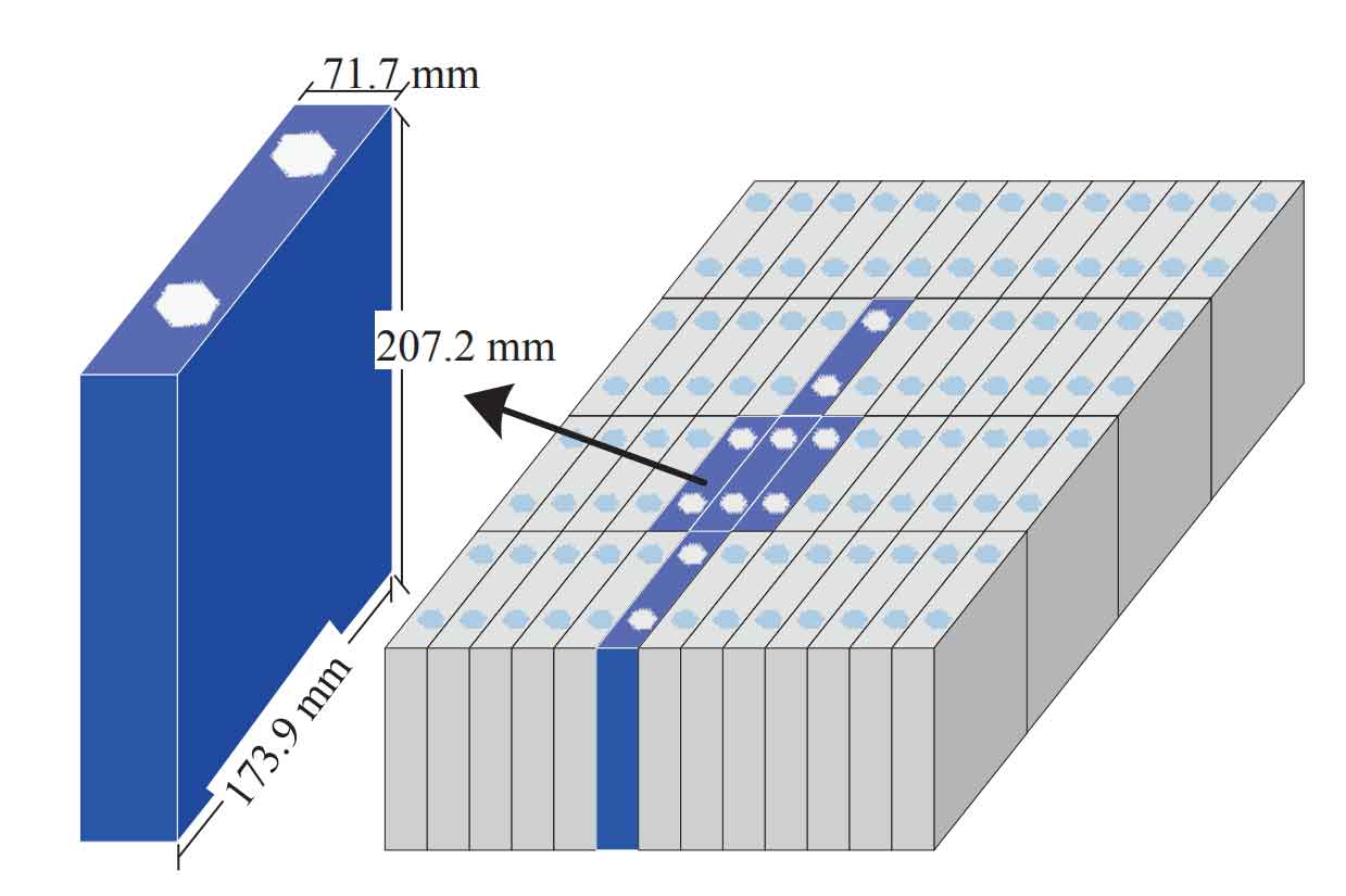
The integration of large-format cells like the 430 Ah unit into a complete cell energy storage system involves assembling them into modules and racks. The image illustrates the progression from a single prismatic cell to a bundled module configuration. The thinner profile of the laminated cell can offer advantages in module thermal management and packing density compared to thicker wound cells, influencing the overall design and safety of the cell energy storage system.
2. Electrochemical Performance and Characterization
Cell performance was evaluated according to standards derived from GB/T 36276-2023. Key metrics included discharge energy, energy efficiency at various temperatures, and cycle life. Tests were conducted using a high-precision battery cycler within a temperature-controlled chamber.
The results, summarized in Table 1, demonstrate that the 430 Ah cell not only achieves higher total energy but also exhibits superior performance characteristics.
| Parameter | 280 Ah Cell | 430 Ah Cell |
|---|---|---|
| Discharge Energy @ 25°C, 0.5P (Wh) | 976 | 1377 |
| Energy Efficiency @ 25°C, 0.5P (%) | 94.3 | 94.8 |
| Low-temp Discharge Energy @ 5°C, 0.5P (Wh) | 782 | 1143 |
| Low-temp Energy Efficiency @ 5°C, 0.5P (%) | 80.5 | 81.5 |
| High-temp Discharge Energy @ 45°C, 0.5P (Wh) | 987 | 1474 |
The energy efficiency (η) is a critical figure of merit for a cell energy storage system, impacting overall round-trip efficiency and operating economics. It is defined as the ratio of discharge energy to charge energy over a full cycle:
$$ \eta = \frac{E_{discharge}}{E_{charge}} \times 100\% $$
where \(E\) represents the integral of power over time during the respective operation. The 430 Ah cell’s higher efficiency, particularly at low temperatures, indicates lower internal polarization and resistance. This is attributed to the laminated structure: the flat electrode layers provide shorter and more uniform ion diffusion paths compared to the long, tortuous path in a wound jellyroll. Furthermore, the PVDF adhesive on the separator promotes intimate contact between the separator and electrode surfaces, reducing interfacial impedance and enhancing ionic conductivity across the stack. This design effectively mitigates the performance penalty often expected when scaling cell capacity.
3. Comprehensive Safety Evaluation
Safety is the most critical consideration for any large-scale cell energy storage system. A rigorous safety test protocol based on international standards was applied to both cell types, including overcharge, over-discharge, external short circuit, crush, and nail penetration tests. The key quantitative metric observed was the maximum temperature rise (ΔT) during these abusive conditions.
| Test | 280 Ah Cell Max. Temp. Rise (ΔT) | 430 Ah Cell Max. Temp. Rise (ΔT) |
|---|---|---|
| Overcharge | 83.2 °C | 57.8 °C |
| Over-discharge | 110.1 °C | 92.8 °C |
| Short Circuit | 372.7 °C | 236.5 °C |
| Nail Penetration | 281.6 °C | 2.2 °C |
| Thermal Runaway (Triggered) | 327.0 °C | 233.7 °C |
The data reveals a consistent and dramatic advantage for the 430 Ah laminated cell across all tests, with the most striking difference observed in the nail penetration test. The wound 280 Ah cell experienced a rapid temperature spike to over 280°C, accompanied by smoke and deformation, indicating the initiation of severe internal short circuits and exothermic reactions. In stark contrast, the 430 Ah cell’s temperature increased by only 2.2°C, remaining near ambient temperature with no visible smoke or sparks.
This exceptional safety performance is a direct consequence of the synergistic design:
- Thermal Management via Laminated Structure: The thin, large-area format of the laminated cell offers a significantly higher surface-area-to-volume ratio compared to the thick, compact wound cell. During an internal short circuit (like nail penetration), the generated heat can be dissipated more effectively over the large surface area, preventing localized hot spots from reaching critical temperatures that trigger cascading reactions. The wound cell’s geometry confines heat radially, leading to rapid heat accumulation in its core.
- Short-Circuit Mitigation via Adhesive-Coated Separator: The PVDF adhesive layer is a pivotal innovation. During a penetration event, the adhesive helps bond the separator to the electrode surfaces. This bonding restricts the separator’s shrinkage and retraction around the penetration site, physically isolating the newly created flaw and preventing it from expanding into a large-area short circuit between the anode and cathode. The ceramic coating further enhances the separator’s melt integrity at high temperatures. In the wound cell without adhesive, the separator can easily retract from the puncture, allowing massive internal shorting across multiple wound layers.
- Mechanical Stability: The laminated stack experiences minimal internal stress during fabrication (near-zero tension stacking) compared to the variable tension applied during the winding process. This results in flatter, more uniform electrodes with fewer micro-wrinkles or strains that could become failure initiation points under abuse.
The safety equation for a cell under internal short circuit can be conceptually simplified by considering the balance between heat generation (Q_gen) and heat dissipation (Q_diss). Catastrophic thermal runaway occurs when Q_gen >> Q_diss.
$$ Q_{gen} = I_{short}^2 \cdot R_{short} \cdot t $$
$$ Q_{diss} \propto A_{surface} \cdot \Delta T \cdot k $$
For the laminated cell, the design minimizes \(I_{short}\) (by limiting short-circuit area via adhesive) and maximizes \(A_{surface}\) for dissipation, while the wound cell suffers from a higher effective \(I_{short}\) and a smaller \(A_{surface}\) relative to its volume, leading to the observed dramatic difference in ΔT.
4. Cycle Life and Degradation Analysis
Long-term cycle stability is economically essential for a cell energy storage system, directly affecting its lifespan and levelized cost. Both cells were subjected to a 0.5P charge/discharge cycle test at 25°C. The capacity retention over cycles is shown in Figure 3 (conceptual data). After 450 cycles, the 430 Ah laminated cell exhibited a capacity retention of 98.5%, outperforming the 280 Ah wound cell which retained 95.5%.
This 3% difference signifies a meaningful extension in operational life. The degradation mechanisms differ due to architecture:
- Wound Cell Degradation: The winding process induces curvature and non-uniform tension on the outer and inner electrode layers. During cycling, lithiation/delithiation causes volume changes in the active materials. In a wound structure, these volume changes are constrained asymmetrically, leading to increased mechanical stress, particularly at the curved regions. This can cause electrode layer detachment, local delamination, and accelerated Solid Electrolyte Interphase (SEI) growth. Furthermore, the longer ionic path in the jellyroll can lead to greater concentration polarization, especially at higher rates, promoting heterogeneous current distribution and localized lithium plating on the anode (evidenced by dark spots in post-mortem analysis), which consumes cyclable lithium and increases impedance.
- Laminated Cell Stability: The flat, stacked electrodes expand and contract more uniformly in-plane. The absence of curvature eliminates stress concentration points. The adhesive separator maintains intimate electrode-separator contact throughout cycling, preventing void formation that can increase local current density. The shorter, more uniform ion transport paths reduce overall polarization, ensuring more homogeneous lithium-ion flux across the electrodes. This mitigates localized over-lithiation or plating, leading to slower and more uniform degradation. The capacity fade can be modeled using a simplified empirical equation, where the laminated design effectively reduces the fade rate constant \(k\):
$$ C_{n} = C_{0} \cdot e^{-k \cdot n} $$
where \(C_n\) is capacity at cycle \(n\), \(C_0\) is initial capacity, and \(k\) is the degradation rate constant.
5. Implications for Cell Energy Storage System Design and Cost
The advancement from 280 Ah to 430 Ah cells with enhanced safety and life has profound implications for the design and economics of a cell energy storage system. The benefits propagate from the cell level to the system level.
| Aspect | System with 280 Ah Wound Cells | System with 430 Ah Laminated Cells | Advantage for 430 Ah System |
|---|---|---|---|
| Cell Count for 1 MWh | ~1025 cells | ~726 cells | ~30% fewer cells |
| Connectors & Busbars | Higher quantity | Lower quantity | Reduced cost, complexity, and failure points |
| Battery Management System (BMS) Channels | More voltage/temperature sensing points | Fewer sensing points | Simplified BMS, lower cost |
| Thermal Management | Challenging due to thick cell geometry; potential hot spots in core. | Easier cooling due to thin, large-surface-area cells; better heat dissipation. | More effective and potentially simpler cooling system. |
| Safety Mitigation | Requires robust spacing, fire suppression for thermal runaway risk. | Inherently safer cell reduces propagation risk; may allow for denser packing. | Lower risk, potentially reduced insurance costs, denser system footprint. |
| Cycle Life & Warranty | Standard degradation profile. | Extended cycle life (≥3% higher retention at 450 cycles). | Longer system warranty, lower lifetime cost per cycle. |
The total cost of ownership (TCO) for a cell energy storage system is a complex function of CapEx (cells, BOP, BMS) and OpEx (efficiency losses, maintenance, replacement). The laminated 430 Ah cell positively impacts both. The reduction in cell count and ancillary components directly lowers CapEx. The higher energy efficiency reduces OpEx energy losses. Most significantly, the enhanced safety profile and longer cycle life decrease the risk and frequency of maintenance or early replacement, which are major contributors to TCO. While the individual 430 Ah cell may have a slightly higher material cost due to the adhesive-coated separator and potentially more complex stacking process, the system-level savings are substantial. This aligns perfectly with the industry’s goal of achieving a lower LCOS, making renewable energy plus storage more economically competitive.
6. Conclusion and Future Perspectives
This study demonstrates that simply increasing the capacity of a lithium-ion battery is not a viable path forward for the next generation of cell energy storage system technology. Instead, a co-optimized design encompassing internal architecture and advanced materials is essential. The development of a 430 Ah Lithium Iron Phosphate cell utilizing a laminated (stacked) structure and an adhesive-coated ceramic separator has been shown to comprehensively outperform a conventional 280 Ah wound cell in critical metrics.
The laminated design fundamentally improves current distribution, reduces internal resistance, and enhances heat dissipation. The adhesive-coated separator acts as a critical safety fuse, dramatically limiting short-circuit propagation during mechanical abuse, as unequivocally proven by the near-ambient temperature rise during nail penetration. Together, these innovations not only maintain but enhance electrochemical performance (energy, efficiency) and significantly extend cycle life compared to the wound counterpart.
The implications for grid-scale and commercial cell energy storage system deployments are significant. This cell technology enables simpler, more compact, and inherently safer system designs with a demonstrably lower total cost of ownership. Future work will focus on further scaling this paradigm, exploring even larger capacities while maintaining the safety principle of “large-area, thin-cell” design. Continued research into advanced adhesive chemistries, faster stacking manufacturing processes, and integrated cell-to-pack designs will be crucial to fully realize the potential of this approach. By prioritizing safety and longevity through intelligent design at the cell level, the industry can build more reliable, economical, and sustainable energy storage systems to support the global clean energy transition.