
In the pursuit of sustainable energy solutions, solar power stands out as a virtually inexhaustible and clean resource. Thin film solar panels, which utilize photoelectric materials only a few micrometers thick, represent a promising advancement in photovoltaic technology. Compared to traditional crystalline silicon panels, thin film solar panels offer advantages such as lower material costs, simplified manufacturing processes, better performance in low-light conditions, higher temperature tolerance, flexibility, tunable colors, and recyclability. These attributes make them ideal for applications like building-integrated photovoltaics (BIPV), driving significant market growth. As a result, modern, intelligent factories for producing thin film solar panels are emerging worldwide. In this context, I focus on designing and implementing an intelligent transmission system that serves as the backbone of these production lines, enabling seamless material handling, process integration, data tracking, and smart manufacturing.
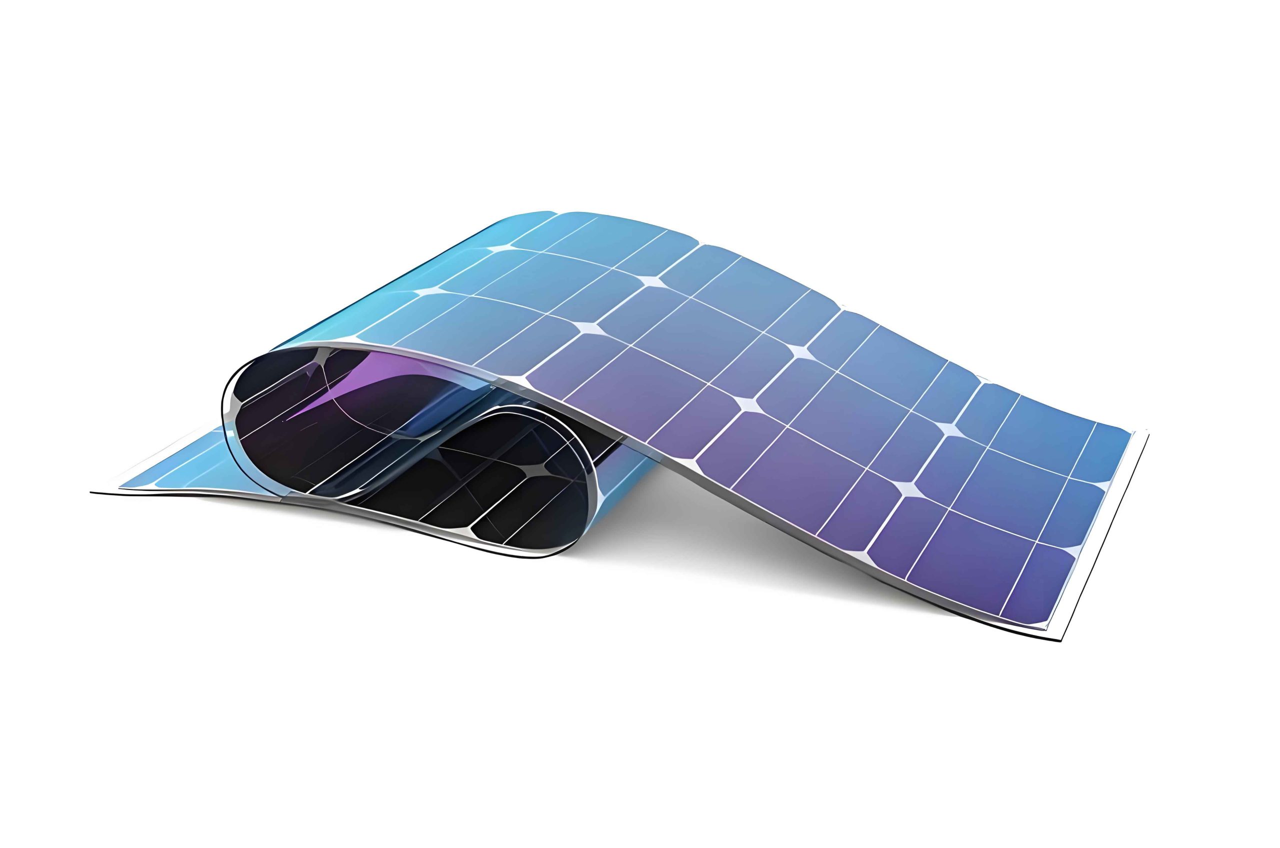
The production of thin film solar panels involves 20 to 30 process steps, including core operations like deposition, laser scribing, and encapsulation. To achieve high efficiency and reliability, an intelligent transmission system must address multiple dimensions: process flow, equipment functionality, informatization, and smart automation. This article delves into a comprehensive solution from a first-person perspective, drawing on practical insights and theoretical frameworks. We will explore demand analysis, system design, and implementation strategies, incorporating tables and formulas to summarize key concepts. Throughout, the term “thin film solar panels” will be emphasized to highlight the specific application domain.
Demand Analysis for Intelligent Transmission Systems
To design an effective intelligent transmission system for thin film solar panel production lines, we must first understand the requirements from process, equipment, informatization, and smart perspectives. This analysis sets the foundation for developing tailored solutions.
Process Requirements
Thin film solar panel production lines typically adopt one of two layout types: linear flow or hybrid composite. In a linear flow layout, substrates move sequentially from start to finish through various process stations, with backplanes introduced at lamination points. Distributed buffering—either online or offline—is incorporated at critical points to ensure continuous operation. The transmission system interconnects these stations, handling substrate transfer, rotation, and temporary storage. For instance, in a line producing large-format thin film solar panels like CdTe modules up to 2 m × 1.23 m or CIGS panels at 1.2 m × 0.6 m, the transmission must accommodate varying sizes and cycle times ranging from tens to hundreds of seconds. Substrates and backplanes are often made of 2–4 mm tempered glass with high light transmittance, requiring careful handling to prevent damage and contamination in cleanroom environments (typically high cleanliness classes).
In hybrid composite layouts, a central hub system coordinates substrate flow through looped process lines and linear segments. Substrates enter the hub, circulate through process loops for treatments like deposition, and return to the hub before proceeding to downstream encapsulation stages. This approach centralizes buffering and routing, enhancing flexibility. The transmission system here must support complex logistics, including transfers between hubs, loops, and linear sections. Key process demands include precise positioning (e.g., ±1 mm accuracy for substrate alignment at equipment interfaces), orientation changes (e.g., long-edge vs. short-edge entry), flipping for deposition processes (e.g., CSS methods requiring face-down orientation), and sufficient buffering to mitigate downtime risks. The table below summarizes these process requirements.
| Requirement Category | Description | Key Parameters |
|---|---|---|
| Substrate Size | Accommodate large formats for thin film solar panels | Up to 2 m × 1.23 m for CdTe; 1.2 m × 0.6 m for CIGS |
| Cycle Time | Match production throughput | 10–100 seconds per panel |
| Positioning Accuracy | Ensure precise alignment for process equipment | ±1 mm or better |
| Orientation Handling | Support rotation and flipping as per process needs | 90° rotation; 180° flipping for deposition |
| Cleanliness | Maintain high cleanliness levels | ISO Class 5–7 equivalent |
| Buffer Capacity | Provide storage to decouple process stages | Varies from 10 to 30,000 panels |
Equipment Requirements
The intelligent transmission system must integrate various functional modules to meet process demands. These include conveyance units, turning mechanisms, rotation devices, flipping stations, alignment systems, and buffering solutions. Each module should be designed with modularity and standardization in mind to facilitate rapid deployment and maintenance. For example, conveyance can use synchronous belts or rubber rollers driven by servo motors for precise control, while alignment might employ pneumatic cylinders with sensors. Buffering solutions range from small online caches to large vertical warehouses, depending on the layout. Equipment must also support high reliability, with mean time between failures (MTBF) exceeding production cycle demands. We can model the overall line efficiency to underscore the importance of buffering. If each process station has an individual uptime efficiency \( \eta_i \), the total line efficiency after \( n \) stations is:
$$ \eta_{\text{total}} = \prod_{i=1}^{n} \eta_i $$
For a thin film solar panel line with \( n = 25 \) and \( \eta_i = 0.98 \) (98% uptime), the theoretical efficiency is:
$$ \eta_{\text{total}} = 0.98^{25} \approx 0.603 $$
This drops to about 60%, highlighting how cascading downtimes can cripple output. Buffering introduces decoupling, allowing upstream and downstream sections to operate independently during station failures. With buffers, the effective efficiency improves, as downtime in one section doesn’t immediately propagate. We can express this with a buffering factor \( \beta \) (0 < β ≤ 1), where higher β indicates better buffer capacity:
$$ \eta_{\text{effective}} = \eta_{\text{total}} + \beta (1 – \eta_{\text{total}}) $$
For instance, with \( \beta = 0.8 \), \( \eta_{\text{effective}} \approx 0.603 + 0.8 \times 0.397 = 0.921 \), showing a significant boost. This mathematical insight drives the need for robust buffering in thin film solar panel lines.
| Equipment Type | Function | Typical Specifications |
|---|---|---|
| Conveyance Unit | Move substrates between stations | Servo-driven belts/rollers; speed 0.1–1 m/s |
| Turning Mechanism | Change direction at line corners | 90° or 180° turns; precision ±0.5° |
| Rotation Device | Adjust substrate orientation | 0–360° rotation; load capacity up to 50 kg |
| Flipping Station | Invert substrates for deposition | 180° flip; cycle time < 5 s |
| Alignment System | Correct position deviations | Pneumatic/servo actuators; accuracy ±1 mm |
| Buffer Storage | Temporarily store panels | Capacity 10–30,000 panels; automated retrieval |
Informatization and Smart Requirements
In the era of Industry 4.0, thin film solar panel factories must leverage informatization and smart technologies to achieve flexible, data-driven manufacturing. The transmission system plays a critical role here by enabling real-time tracking, data exchange, and integration with higher-level systems like Manufacturing Execution Systems (MES) and Enterprise Resource Planning (ERP). Key requirements include: (1) Substrate identification and tracking using QR code or RFID readers at each process entrance; (2) Standardized communication protocols (e.g., PROFINET, TCP/IP) for horizontal data exchange between transmission and process equipment; (3) SECS/GEM interface software for vertical integration with MES, allowing commands, recipes, and production data to flow seamlessly; (4) Data analytics capabilities to optimize routing and buffer management. The smart transmission system should act as a cyber-physical system, where physical handling is guided by digital twins and predictive algorithms. For example, machine learning can forecast equipment failures and pre-adjust buffer allocations to minimize disruptions in thin film solar panel production. The following formula represents data flow latency \( L \) in such a system, where \( d \) is data packet size, \( b \) is bandwidth, and \( n \) is node hops:
$$ L = \sum_{i=1}^{n} \left( \frac{d}{b_i} + \delta_i \right) $$
Here, \( \delta_i \) is processing delay at node \( i \). Minimizing \( L \) ensures real-time responsiveness for smart decisions. Additionally, the system must support modular software blocks for functions like handshake signaling, error handling, and inventory management, enabling plug-and-play expansion. The table below outlines these smart requirements.
| Requirement Area | Details | Standards/Technologies |
|---|---|---|
| Data Tracking | Real-time ID and status monitoring for each thin film solar panel | QR code/RFID; SCADA for data aggregation |
| Communication Protocols | Horizontal device-to-device and vertical system integration | PROFINET, Ethernet/IP; SECS/GEM for MES |
| Interface Software | Enable MES/ERP connectivity and control | Custom SDKs; OPC UA for interoperability |
| Analytics and Optimization | Use data to improve throughput and reduce downtime | Machine learning algorithms; digital twin simulations |
| Modularity | Software and hardware components for easy upgrades | Object-oriented programming; standardized APIs |
Comprehensive Solutions for Intelligent Transmission Systems
Based on the demand analysis, we propose a holistic solution for intelligent transmission systems in thin film solar panel production lines. This solution encompasses process design, equipment configuration, and smart informatization, all aimed at maximizing efficiency, flexibility, and intelligence.
Process Design Solutions
The process layout dictates how substrates flow through the line. We advocate for a modular approach where the transmission system is composed of standardized units between process stations. Each unit’s length is determined by substrate size; for a 2 m × 1.23 m thin film solar panel, a standard unit length of 2.4 m allows for 200 mm margins at both ends for acceleration, deceleration, and positioning. The number of units between stations follows three principles: (1) Fit within factory layout constraints, ensuring no interference and adequate maintenance space; (2) Fulfill process functions like turning, rotating, flipping, or buffering as required; (3) Incorporate standby positions to buffer against upstream failures. The quantity of standby positions \( S \) can be calculated based on downstream equipment characteristics:
$$ S = \ceil{ \frac{T_{\text{response}} + T_{\text{recovery}}}{T_{\text{cycle}}} } $$
Here, \( T_{\text{response}} \) is the average time to respond to a failure, \( T_{\text{recovery}} \) is the recovery time, and \( T_{\text{cycle}} \) is the production cycle time. For instance, if \( T_{\text{response}} = 120 \) s, \( T_{\text{recovery}} = 300 \) s, and \( T_{\text{cycle}} = 30 \) s, then \( S = \ceil{ (120+300)/30 } = \ceil{14} = 14 \) positions. This ensures continuity during disruptions.
Buffering strategies vary by layout. In linear flows, distributed buffering—small caches at key points—is effective. For hybrid layouts, centralized hub buffering with large vertical warehouses optimizes space and management. The choice depends on throughput goals and floor space. Below is a comparison table.
| Layout Type | Buffering Approach | Advantages | Typical Capacity |
|---|---|---|---|
| Linear Flow | Distributed online/offline caches | Simple integration; local decoupling | 10–100 panels per cache |
| Hybrid Composite | Centralized vertical warehouses | High density; centralized control | 1,000–30,000 panels |
These designs ensure that thin film solar panel production remains resilient and adaptable to varying demands.
Equipment Configuration Solutions
Equipment must be modular, standardized, and smart-enabled. We propose the following configurations for key transmission components:
- Conveyance Units: Use aluminum or steel frames with synchronous belts or rubber rollers. Servo motors provide precise speed and position control, while remote I/O modules (e.g., PROFINET-based) reduce wiring complexity and enhance anti-interference. For cleanroom areas, sealed enclosures prevent contamination.
- Turning and Rotation Devices: Implement gear-driven turntables or belt-driven curves with servo control for smooth orientation changes. Position feedback via encoders ensures accuracy within ±0.5°.
- Flipping Stations: Design with dual-arm mechanisms or vacuum grippers that rotate 180° around a horizontal axis. Safety sensors detect substrate presence to prevent drops.
- Alignment Systems: Integrate pneumatic cylinders with vision systems or edge sensors. A common approach uses two perpendicular actuators to nudge the substrate into position, achieving ±1 mm repeatability.
- Buffering Solutions: Deploy three tiers: (1) Online caches—overhead units with servo-driven lifts and grippers for 10–30 panels; (2) Offline mini-warehouses—rack-based systems with shuttle cars for 100–500 panels; (3) Large vertical warehouses—automated storage and retrieval systems (AS/RS) with Warehouse Management Systems (WMS) and Warehouse Control Systems (WCS) for thousands of thin film solar panels. These AS/RS use algorithms like first-in-first-out (FIFO) or dynamic slotting to optimize retrieval times.
The equipment’s software should encapsulate functional blocks—e.g., a “conveyor control” module or “buffer management” module—that can be reused across units. This modularity speeds up debugging and maintenance. We can model the reliability of such a system using an exponential distribution for failure rates. If each module has a failure rate \( \lambda \) (failures per hour), the system’s mean time to failure (MTTF) for \( m \) series modules is:
$$ \text{MTTF}_{\text{system}} = \frac{1}{\sum_{j=1}^{m} \lambda_j } $$
With redundancy in critical modules, MTTF improves. For instance, if buffering modules have parallel redundancy, the effective failure rate reduces, enhancing uptime for thin film solar panel production.
Below is a summary of equipment specifications.
| Equipment Component | Design Features | Performance Metrics |
|---|---|---|
| Conveyance Unit | Modular frame; servo drive; remote I/O | Speed: 0.5 m/s; positioning error < ±2 mm |
| Turning Mechanism | Curved belt or turntable; encoder feedback | Turn time: 3 s; accuracy ±0.5° |
| Rotation Device | Servo-driven platform; load adapters | Rotation time: 5 s; 0–360° programmable |
| Flipping Station | Dual-arm gripper; safety sensors | Flip cycle: 4 s; payload up to 40 kg |
| Alignment System | Pneumatic actuators; vision guidance | Alignment time: 2 s; accuracy ±1 mm |
| Online Cache | Overhead lift; gripper mechanism | Capacity: 20 panels; retrieval time: 10 s |
| Offline Mini-Warehouse | Rack and shuttle; servo control | Capacity: 200 panels; throughput: 30 panels/hour |
| Vertical AS/RS | Stacker cranes; WMS/WCS integration | Capacity: 10,000+ panels; throughput: 100 panels/hour |
Informatization and Smart Solutions
The intelligence of the transmission system hinges on robust informatization. We propose a layered architecture aligned with the automation pyramid: ERP at the top, MES in the middle, and equipment controls at the base. The transmission system interfaces horizontally with process equipment and vertically with MES via SECS/GEM. Key implementations include:
- Data Tracking and Acquisition: Install barcode readers at every process entrance to scan thin film solar panel IDs. A centralized SCADA system collects real-time data on panel location, status, and historical route. Each transmission unit communicates via standardized handshake signals—e.g., using PROFINET with defined input/output tags for “panel present,” “ID confirmed,” and “ready for transfer.” This ensures seamless data flow. The handshake protocol can be modeled as a state machine with states like IDLE, TRANSFER, and CONFIRM, reducing errors.
- MES Integration: Develop SECS/GEM interface software that translates MES commands (e.g., “start lot,” “change recipe”) into equipment actions. Use TCP/IP over Ethernet for communication, with star topology to minimize collisions. The software handles scenarios like recipe downloads, alarm reporting, and data collection. For example, when MES sends a production order for a batch of thin film solar panels, the transmission system routes panels accordingly and feeds back completion events.
- Smart Analytics: Leverage data to optimize performance. Machine learning algorithms can predict buffer needs based on historical downtime patterns. A digital twin of the transmission system—a virtual replica—allows simulation of layout changes or throughput adjustments without disrupting production. We can formulate an optimization problem to minimize total handling time \( T_{\text{total}} \):
$$ \min T_{\text{total}} = \sum_{k=1}^{K} \left( t_{\text{convey},k} + t_{\text{buffer},k} + t_{\text{process},k} \right) $$
Subject to constraints like buffer capacity \( B_{\text{max}} \) and cycle time limits \( C_{\text{max}} \). Solving this with linear programming or genetic algorithms yields efficient schedules for thin film solar panel flows.
The communication network uses Ethernet switches to connect PLCs, SCADA, and MES. Data packets are formatted according to ISO/OSI layers, ensuring compatibility. The table below outlines the smart solution components.
| Component | Function | Implementation Details |
|---|---|---|
| SCADA System | Real-time monitoring and control | HMI with dashboards; data logging to SQL databases |
| Handshake Protocol | Ensure reliable panel transfers | PROFINET I/O; state machine with error recovery |
| SECS/GEM Interface | Bridge between MES and equipment | C++/Python software; supports HSMS over TCP/IP |
| Digital Twin | Simulate and optimize transmission | 3D model in Unity or similar; integrates with PLC data |
| Predictive Analytics | Forecast failures and buffer needs | ML models (e.g., random forests) on historical data |
This smart framework transforms the transmission system into an adaptive, learning entity that continuously improves thin film solar panel production efficiency.
Conclusion
The intelligent transmission system is a cornerstone of modern thin film solar panel production lines, enabling high throughput, flexibility, and data-driven decision-making. By addressing process, equipment, and smart requirements, we can design systems that not only convey substrates but also optimize entire manufacturing flows. Modular equipment, coupled with advanced informatization like SECS/GEM interfaces and predictive analytics, ensures resilience against disruptions and paves the way for fully automated, intelligent factories. As the demand for thin film solar panels grows, such transmission solutions will be critical to scaling production sustainably and efficiently. Future work may explore deeper AI integration or quantum computing for real-time optimization, but the foundations laid here provide a robust starting point for innovation in thin film solar panel manufacturing.