
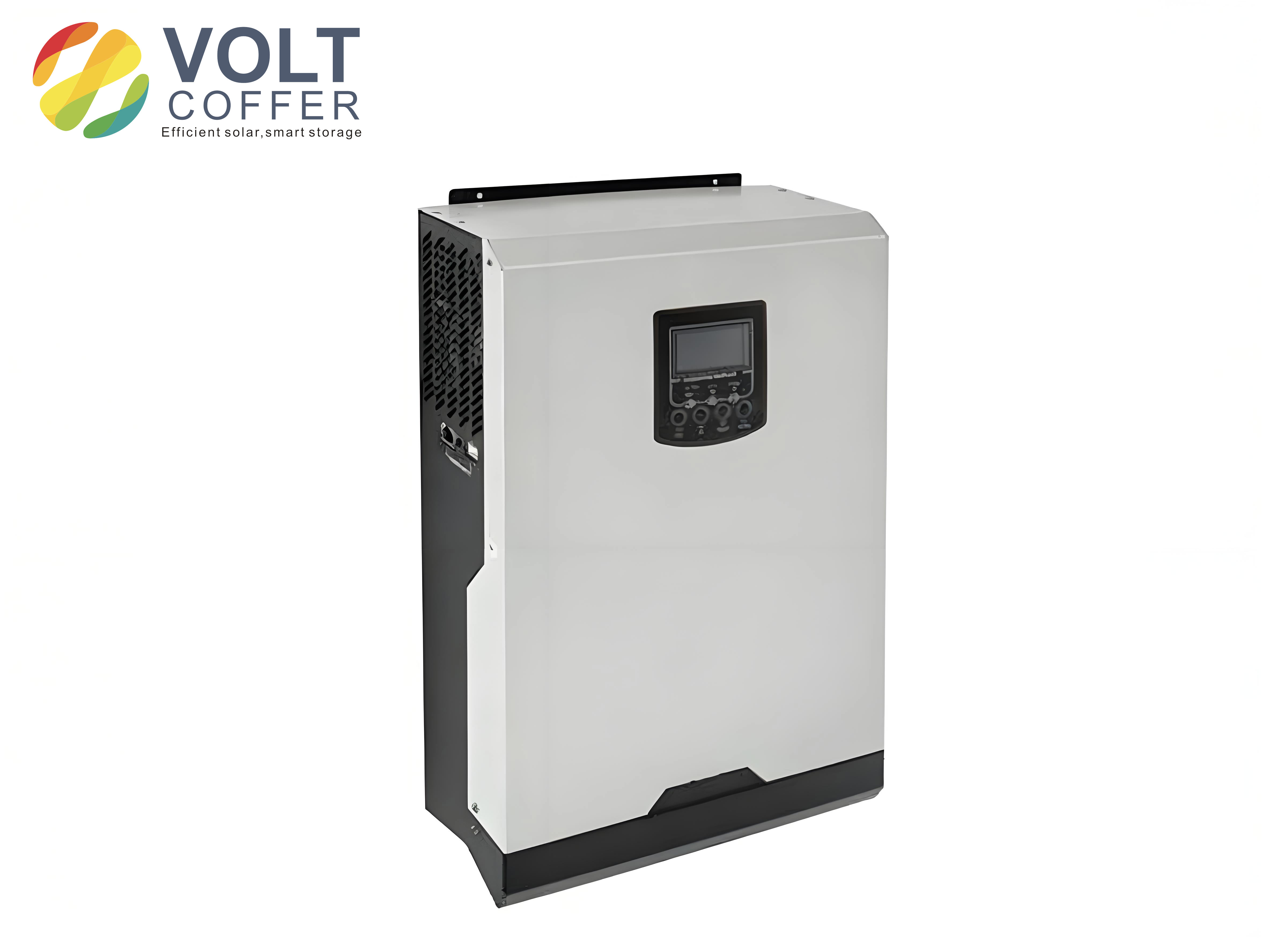
Managing High Export Voltage in Distributed Solar Inverters
In recent years, the share of distributed photovoltaic generation in rural distribution networks has increased dramatically. Small rooftop solar systems, agricultural facility PV arrays, and village-level collective projects are now common sights. However, many distributed PV inverters are configured with export voltage setpoints that exceed the limits specified by national standards and related documents. This situation has created significant risks for the safety of everyday electricity use and for the stable operation of the power system. In power grid monitoring systems, alarms for “distributed PV grid-connection voltage exceeding the upper limit” are becoming increasingly frequent. These alarms affect the voltage quality index of the entire distribution network, and they also have a negative impact on the lifetime and safe operation of the solar inverter itself. Based on the problems I have encountered in actual field work, I would like to discuss concrete control and governance measures for this issue.
1. Regulatory Requirements for Solar Inverter Export Voltage
According to the Chinese national standard GB/T 12325—2008 “Power Quality – Voltage Deviation of Supply Voltage”, for three-phase power supply at 20 kV and below, the allowable voltage deviation is ±7% of the nominal system voltage. For 220 V single-phase power supply, the allowable deviation is +7% and -10% of the nominal system voltage. This yields a permissible range of 198 V to 235.4 V for a 220 V single-phase system. In addition, the “Measures for Power Quality Management (Interim)” and the industry standard DL/T 2041—2019 “Guidelines for the Evaluation of Distributed Power Generation Access to the Power Grid” further specify the requirements. Based on these laws, regulations, and industry standards, I recommend that the export voltage of a 220 V distributed solar inverter be set within the range of 198 V to 235.4 V, while for a 380 V distributed solar inverter the export voltage should be set within 353.4 V to 406.6 V. For new PV installations connected after the implementation of this guideline, all inverter voltage settings should be uniformly configured according to these ranges.
Because the distribution transformer area voltage must be coordinated with the export voltage of the distributed solar inverter, there are also requirements in the State Grid Corporation’s “Distributed Power Access to Distribution Network Related Technical Specifications (Revised Edition)” for inverter-type distributed generation connected to the 220 V / 380 V distribution network. These specifications state that the inverter must comply with relevant national and industry technical standards, and must have under-voltage/over-voltage blocking capability and automatic reconnection after voltage recovery. The voltage protection operating times are shown in the table below. In addition, the inverter should automatically reconnect to the grid when the voltage recovers to 85% of the nominal voltage.
| Voltage at point of common coupling | Requirement |
|---|---|
| U < 50% UN | Maximum opening time no more than 0.2 s |
| 50% UN ≤ U < 85% UN | Maximum opening time no more than 2.0 s |
| 85% UN ≤ U < 110% UN | Continuous operation |
| 110% UN ≤ U < 135% UN | Maximum opening time no more than 2.0 s |
| U ≥ 135% UN | Maximum opening time no more than 0.2 s |
Note: UN is the rated grid voltage at the point of common coupling. The maximum opening time is defined as the time from the occurrence of the abnormal state to the moment when the distributed generator stops sending power to the grid.
These limits are not arbitrary. They are based on the physical capabilities of electrical equipment and the safe operating envelope of grid-connected solar inverters. Modern solar inverters are designed to operate within a certain voltage window. When the export voltage exceeds the upper limit, the internal DC-link voltage rises, the switching devices experience higher stress, and the electrolytic capacitors age faster. In my inspections, I have seen multiple solar inverters with burned IGBT modules and swollen capacitors caused by prolonged operation at elevated voltages. Therefore, adhering to the export voltage settings is not merely a regulatory obligation; it is a practical necessity for preserving the reliability of the solar inverter and the safety of the distribution network.
2. Responsibilities of Different Stakeholders in Solar Inverter Export Voltage Control
The management of solar inverter export voltage involves multiple parties. Each party has distinct responsibilities and roles. Based on my experience, a clear division of responsibilities is essential for effective governance.
2.1 Responsibilities of Distributed PV Investment Entities
Each distributed photovoltaic investment entity (such as a PV system owner, an operator, or an energy service company) should establish and improve its own power quality management system in accordance with national standards and related documents. The entity must designate a department and specific personnel responsible for power quality management. They should carry out power quality information collection, analysis, and self-inspection to ensure that the solar inverter export voltage remains within the prescribed ranges. In practice, however, many small-scale PV owners lack the technical expertise to adjust inverter parameters correctly. Some even intentionally raise the export voltage setpoint to inject more active power into the grid, thinking that doing so will increase their revenue. This practice is extremely dangerous. It not only violates grid codes but also leads to frequent inverter tripping and accelerated component degradation. Therefore, investment entities must be educated and supervised to follow the rules.
2.2 Responsibilities of Municipal and County Power Supply Companies
Municipal and county power supply companies must strengthen the operation supervision and management of distributed PV systems. They should routinely monitor the export voltage of distributed solar inverters within their jurisdiction. In my work, we have established a special task force to conduct grid-connection inspections. The key inspection items include:
- Whether protection devices are installed and put into operation.
- Whether inverter parameters have been privately adjusted without approval.
- Whether the power quality meets the national standards.
- Whether there are any hidden safety hazards in grid-connected equipment.
We usually use a multimeter to measure the voltage on-site, or we extract voltage data from the electricity information collection system for analysis. Through these methods, we can identify solar inverters with export voltage beyond the limits. The power supply company can also take the lead in organizing symposiums and regular briefings to disclose the distributed PV entities whose inverter export voltages have exceeded the limits. For those that violate relevant laws, regulations, and document requirements, the power supply company should issue a rectification notice with a time limit. If the entity refuses to rectify, the connection to the grid can be terminated in accordance with regulations.
2.3 Responsibilities of Development and Reform Commissions
The municipal, county, and district development and reform commissions may carry out supervision and inspection when necessary. If illegal or non-compliant behavior is found during such inspections, the commission should correct it on the spot or order rectification within a specified period. This higher-level oversight provides an additional enforcement mechanism beyond the power supply company’s operational role. In my experience, the involvement of government authorities significantly increases the compliance rate because distributed PV operators are more likely to take corrective actions when they face regulatory penalties.
3. Difficulties in the Control of Solar Inverter Export Voltage
Despite the clear regulatory framework, my field experience has revealed several difficulties in the control of solar inverter export voltage. These difficulties can be categorized into three main areas: regulation difficulty, collaboration difficulty, and coordination difficulty.
3.1 Regulation Difficulty
The first challenge is the difficulty of regulation. Many distributed PV investment entities do not attach sufficient importance to the issue of inverter export voltage exceeding limits. They often ignore the safety of the grid and their own equipment. Because the solar inverter operates for long periods at high voltage, failures such as burnouts and short circuits occur. In one case I investigated, a photovoltaic module string’s DC side was damaged because the solar inverter’s AC output voltage was set to 250 V instead of the allowed 235.4 V. The resulting sustained overvoltage caused the DC bus capacitors to rupture. This lack of awareness leads to repeated violations. The power supply company at the grassroots level must therefore maintain continuous supervision, which places a heavy burden on the already limited workforce. We need to conduct regular training sessions and publish cases of inverter failures caused by high voltage to improve awareness among PV operators.
3.2 Collaboration Difficulty
The second challenge is the lack of collaboration between PV operating companies and the power supply company. In many regions, the PV operating company and the power supply company do not communicate effectively. There is no information-sharing mechanism for governance progress and discovered problems. Without a joint problem-solving approach, the governance work cannot be carried out smoothly. For example, when we notify a PV operator that a particular solar inverter has exceeded the voltage limit, the operator may not respond in time because the inverter’s internal software requires a password that only the manufacturer knows. This is a common practical issue. The power supply company should actively communicate with the PV operating company and establish a communication and coordination mechanism as soon as possible. In my team, we have set up a WeChat group that includes technical staff from all major PV operators in the county. Through this group, we share real-time voltage data and coordinate the adjustment of inverter settings. This approach has greatly improved the efficiency of rectification.
3.3 Coordination Difficulty
The third challenge is the coordination difficulty between the distribution transformer tap changer and the solar inverter export voltage. The tap position of the distribution transformer in the station area must be adjusted in coordination with the output voltage of the distributed solar inverter. If the inverter export voltage is lower than the alarm value of the voltage inverter system in the distribution network and the generated power cannot be uploaded to the grid, it may be necessary to lower the tap position of the distribution transformer. However, lowering the tap position may cause low voltage at the end of customers with long supply radii. This creates a dilemma: raising the tap position to improve the end-of-line voltage can further increase the already high inverter export voltage, while lowering the tap position to reduce the inverter export voltage can cause low voltage problems for downstream customers. To solve this coordination difficulty, the power supply company should actively communicate with the PV operating company and carry out technical upgrades. In particular, the power supply company should first upgrade its own equipment, such as replacing the transformer with an on-load tap-changing (OLTC) transformer or installing voltage regulators at appropriate locations. These upgrades can help stabilize the voltage profile and allow the solar inverter to operate within its acceptable range. Only after the grid-side transformation can the overall upgrade of the system be completed.
4. Technical Analysis of Voltage Variation with Distributed Solar Inverters
To better understand why the export voltage of a solar inverter can exceed the upper limit, it is useful to perform a simple voltage drop calculation. Consider a distribution feeder with a resistance \(R\) and reactance \(X\). The load or generation connected at the end of the feeder introduces an active power \(P\) and reactive power \(Q\). For a distributed solar inverter connected to the low-voltage grid, the voltage rise \(\Delta U\) at the point of connection due to the injected power can be expressed approximately as:
$$ \Delta U \approx \frac{PR – QX}{U_{0}} $$
where \(U_{0}\) is the voltage at the sending end (transformer secondary side), \(P\) is the active power injected by the solar inverter, and \(Q\) is the reactive power injected (positive if leading, negative if lagging). In most distributed PV systems, the solar inverter operates with a power factor close to unity, so \(Q \approx 0\). The voltage rise then simplifies to:
$$ \Delta U \approx \frac{PR}{U_{0}} $$
This equation demonstrates that the voltage rise is directly proportional to the active power injected by the solar inverter. When the PV output is high (e.g., at noon on a sunny day), the injected \(P\) is large, and the voltage at the inverter terminal may rise significantly. If the feeder is long and has high resistance, the voltage rise can be substantial. For example, in a rural distribution network where the transformer secondary voltage is 400 V line-to-line, a typical solar inverter outputting 50 kW at a power factor of unity could cause a voltage rise of several volts, depending on the feeder impedance. The problem becomes even worse at the end of a long radial feeder.
To quantify the allowed voltage deviation, let us define the nominal voltage \(U_{N}\). For a 220 V single-phase system:
$$ U_{\text{max}} = U_{N} \times (1 + 0.07) = 220 \times 1.07 = 235.4 \text{ V} $$
$$ U_{\text{min}} = U_{N} \times (1 – 0.10) = 220 \times 0.90 = 198.0 \text{ V} $$
For a 380 V three-phase system:
$$ U_{\text{max,3\phi}} = 380 \times 1.07 = 406.6 \text{ V} $$
$$ U_{\text{min,3\phi}} = 380 \times 0.93 = 353.4 \text{ V} $$
These formulas are essential when configuring the solar inverter’s trip setpoints. In practice, I recommend adding a small safety margin to avoid nuisance tripping due to measurement errors. For example, the overvoltage trip point setpoint for a 220 V system could be set to 235.0 V instead of 235.4 V. But care must be taken not to set it too low, because a normal grid voltage fluctuation could then trip the inverter unnecessarily, reducing the PV system’s availability.
Another important parameter is the power factor control of the solar inverter. Modern solar inverters can adjust their reactive power output to help regulate voltage. If the inverter is set to absorb reactive power during high voltage conditions, the voltage rise can be mitigated. The relationship between reactive power and voltage is:
$$ U_{2} = U_{1} – \frac{RP + XQ}{U_{1}} $$
where \(U_{1}\) is the voltage at the inverter terminal and \(U_{2}\) is the voltage at the point of common coupling. By controlling \(Q\) to be negative (i.e., absorbing reactive power), the voltage can be reduced. This is known as Q(V) control or volt-var control. However, in many small distributed solar inverters, the default setting is a fixed power factor of 1.0. Changing this setting requires access to the inverter’s advanced menu, which many installers are not familiar with. Therefore, I recommend that the grid company provide clear technical guidelines for inverter settings, including the volt-var curve for different feeder conditions.
In addition to reactive power control, active power curtailment can also be used to limit the export voltage. If the voltage at the inverter terminal exceeds a certain threshold, the inverter can reduce its active power output. The active power derating curve can be expressed as:
$$ P_{\text{out}} = \begin{cases} P_{\text{MPPT}} & \text{if } U \leq U_{1\text{start}} \\ P_{\text{MPPT}} – \frac{P_{\text{MPPT}}}{U_{2\text{end}} – U_{1\text{start}}} \cdot (U – U_{1\text{start}}) & \text{if } U_{1\text{start}} < U < U_{2\text{end}} \\ 0 & \text{if } U \geq U_{2\text{end}} \end{cases} $$
where \(U_{1\text{start}}\) is the voltage at which curtailment begins, and \(U_{2\text{end}}\) is the voltage at which the inverter stops delivering power. This approach is often used as a last resort because it reduces the energy yield of the solar system. However, it is a reliable way to prevent overvoltage when grid infrastructure upgrades are not yet complete.
5. Field Inspection and Data Analysis Methods
In my daily work, I use two main methods to assess whether a solar inverter’s export voltage is within the acceptable range: on-site measurement and remote data analysis.
5.1 On-Site Measurement
For on-site measurement, I use a calibrated true-RMS multimeter or a power quality analyzer. The measurement point should be at the output terminals of the solar inverter or at the point of grid connection. It is important to measure all three phases for a three-phase inverter, and to record the voltage values at different times of the day, especially during peak solar irradiance. The table below shows an example of voltage measurements taken at a 220 V distributed PV site:
| Time of day | Irradiance (W/m²) | Inverter output (W) | Voltage at inverter terminal (V) | Status |
|---|---|---|---|---|
| 09:00 | 400 | 1,200 | 228.5 | Normal |
| 11:00 | 750 | 3,250 | 233.8 | Normal |
| 13:00 | 900 | 4,100 | 238.2 | Exceeded |
| 14:00 | 850 | 3,900 | 237.6 | Exceeded |
| 16:00 | 500 | 2,100 | 230.1 | Normal |
These measurements immediately reveal that the inverter’s export voltage exceeds 235.4 V during the midday period. The likely cause is a combination of high PV output, weak feeder impedance, and the transformer tap position. The inverter settings should be checked and adjusted accordingly.
5.2 Remote Data Analysis
Remote analysis utilizes the electricity information collection system (also known as smart meter reading system). The smart meters installed at PV generation sites usually record voltage, current, and power at 15-minute intervals. I can retrieve these data from the central server and plot the voltage profile over a day. This method is efficient for screening many sites in a short time. The following table shows a sample of voltage data retrieved from a 380 V distributed PV site:
| Time | Voltage A-B (V) | Voltage B-C (V) | Voltage C-A (V) | Active power (kW) | Reactive power (kvar) |
|---|---|---|---|---|---|
| 12:30 | 398.5 | 399.2 | 397.8 | 62.4 | -1.2 |
| 12:45 | 402.3 | 403.1 | 401.6 | 65.8 | -1.5 |
| 13:00 | 406.3 | 407.2 | 405.5 | 68.9 | -1.8 |
| 13:15 | 409.8 | 410.5 | 408.9 | 70.2 | -2.0 |
| 13:30 | 408.7 | 409.4 | 407.6 | 69.5 | -1.9 |
In this case, the line-to-line voltages exceed the upper limit of 406.6 V. The reactive power is slightly negative, indicating the solar inverter is absorbing a small amount of reactive power. Still, the voltage is too high. After inspecting the site, we found that the transformer tap position was set in a high position to compensate for long-distance tail-end voltage drops. However, because the PV system was located very close to the transformer, the high tap position caused overvoltage at the inverter terminal. The solution was to adjust the transformer tap to a lower position and install a line voltage regulator at the end of the feeder to maintain the tail-end voltage. After this adjustment, both the inverter export voltage and the tail-end customer voltage remained within allowable ranges.
6. Practical Control and Governance Measures
After years of hands-on work, I have summarized a set of practical measures that have been effective in reducing the number of distributed PV inverter export voltage violations in our region.
6.1 Setting Adjustment of the Solar Inverter
The most direct measure is to adjust the exported voltage limits inside the solar inverter. According to the regulations, the following settings are recommended:
| System type | Voltage range (V) | Recommended overvoltage trip setting (V) | Recommended undervoltage trip setting (V) |
|---|---|---|---|
| 220 V single-phase | 198.0 – 235.4 | 235.0 | 198.5 |
| 380 V three-phase | 353.4 – 406.6 | 406.0 | 354.0 |
Note that the actual settings must be entered into the inverter’s control menu. Different manufacturers use different naming conventions. For example, one popular 220 V solar inverter uses the parameter “OVP” for overvoltage protection point and “UVP” for undervoltage protection point. In another 380 V inverter, the parameter is “V_HI” and “V_LO”. It is crucial to consult the user manual before changing any parameter. After the adjustment, the inverter should be restarted, and the voltage should be monitored for at least one full sunny day.
6.2 Reactive Power Control Optimization
To reduce the voltage rise without curtailing active power, the solar inverter can be configured with a volt-var control curve. The curve is defined by several setpoints. A typical curve is shown in the table below:
| Voltage (pu) | Reactive power injection (pu) |
|---|---|
| 0.90 | +0.44 (capacitive) |
| 0.95 | +0.20 |
| 1.00 | 0 |
| 1.05 | -0.20 |
| 1.10 | -0.44 (inductive) |
Here, positive reactive power means the inverter supplies reactive power (leading power factor), while negative reactive power means the inverter absorbs reactive power (lagging power factor). The pu values are based on the inverter’s rated reactive power capability. By absorbing reactive power when the voltage is high, the solar inverter can help keep the voltage within the desired range. However, the reactive power capacity of the inverter may be limited by its apparent power rating. The relationship between active power \(P\), reactive power \(Q\), and apparent power \(S\) is:
$$ S^2 = P^2 + Q^2 $$
Therefore, when the solar inverter is producing full active power, its available reactive power capacity is reduced. For example, a 10 kW inverter with a rated apparent power of 10 kVA can supply 0 kvar when active power is 10 kW. To provide reactive power, it must derate its active power. In many cases, a modest reactive power absorption (e.g., 0.1 to 0.2 pu) is sufficient to prevent overvoltage, and the resulting loss of active power is negligible.
6.3 Transformer Tap Coordination
Another important measure is the coordination of transformer taps. In rural distribution networks, many transformers have off-circuit tap changers that must be adjusted with the transformer de-energized. This is a cumbersome process, and the tap position is often set once and left unchanged for years. With the increasing penetration of distributed PV, the voltage profile has changed dramatically. A tap position that was appropriate in winter may be too high in summer when PV output is abundant. I recommend that the power supply company conduct a voltage profile study for every distribution transformer area that hosts distributed PV systems. The study should consider both peak load and peak generation scenarios. The optimal tap position is the one that keeps all customer voltages within the allowable range while also keeping the solar inverter export voltage below its upper limit. In some cases, an on-load tap-changing transformer may be necessary, especially in areas with high PV penetration and long feeders. Although the initial investment is higher, OLTC transformers provide dynamic voltage regulation and solve the coordination problem without de-energizing the transformer.
6.4 Installation of Voltage Regulation Equipment
Where the feeder is long and has a high resistance, a line voltage regulator or a series capacitor can be used to improve voltage regulation. A shunt capacitor alone is not suitable because it can actually raise the voltage further during high PV output. Instead, a step voltage regulator (SVR) installed at the midpoint of the feeder can boost the voltage at the tail end when needed, allowing the transformer tap to be set to a lower position for the benefit of the PV inverters. In one rural project, we installed a 100 kVA line voltage regulator on a feeder with a total length of 1.2 km. The number of voltage violation complaints at the tail end decreased by 90%, and the distributed PV inverters near the transformer stopped tripping on overvoltage. This is a clear demonstration that grid-side upgrades are essential for accommodating distributed solar generation.
6.5 Communication and Training
Finally, effective communication and training cannot be overemphasized. The power supply company should hold annual workshops for PV system owners, installers, and operators. The workshops should cover:
- The national standard voltage limits for solar inverter export voltage.
- The correct procedure to check inverter settings.
- The consequences of violating voltage limits, including accelerated inverter failure and potential grid penalties.
- The use of remote monitoring platforms to view real-time voltage data.
In our region, we have distributed a simple one-page data collection sheet that all PV operators are required to submit monthly. The sheet records the maximum, minimum, and average voltage of each solar inverter during peak solar hours. Using this data, we can quickly identify problematic units and send targeted rectification notices. This proactive approach has reduced the number of voltage violation alarms by about 65% over the past year.
7. Economic and Safety Implications
Operating a solar inverter at an excessively high export voltage is not only a compliance issue, but also an economic issue. From the perspective of the PV system owner, high voltage operation can reduce the inverter’s efficiency. The power electronic switches in the solar inverter have higher switching losses when the DC bus voltage is elevated. Moreover, the inverter may derate its output power to protect itself from overvoltage, resulting in lower energy yield. I have measured cases where an inverter operating at 238 V instead of 230 V produced 3-5% less energy than expected. Over a year, this loss can be substantial.
From the safety perspective, sustained high voltage accelerates the aging of capacitor insulation, degrades the thermal performance of semiconductor devices, and increases the risk of electrical arcing. In the worst case, the solar inverter may fail catastrophically, causing a fire. There have been reported incidents in other provinces where overheating of an overvoltage-stressed solar inverter ignited the rooftop mounting frame. Although such events are rare, the risk is real. Therefore, I always emphasize to PV operators that setting the inverter export voltage according to the national standard is for their own benefit, not just to satisfy the grid company.
8. Future Trends and Recommendations
The rapid growth of distributed PV will continue to challenge the distribution network. In the future, advanced solar inverters with grid-forming capabilities may play a role in voltage regulation. Unlike traditional grid-following inverters, grid-forming inverters can establish a voltage reference and provide inertia. This may help stabilize the voltage profile in weak rural grids. However, the existing installed base of grid-following inverters will still require careful management and supervision.
I also recommend more stringent access requirements for new distributed PV systems. Before a solar inverter is connected to the grid, the installer should provide a signed certificate stating that the inverter settings are in compliance with the national standard. The power supply company should verify these settings by inspecting a random sample of installations. The certificate should include the exact values of all voltage protection setpoints, as shown in the table below:
| Parameter | Value | Acceptance criteria |
|---|---|---|
| Overvoltage trip setpoint | 235.4 V (for 220 V) or 406.6 V (for 380 V) | ±0.5 V |
| Undervoltage trip setpoint | 198.0 V (for 220 V) or 353.4 V (for 380 V) | ±0.5 V |
| Overvoltage trip time | ≤ 2.0 s | Complies with table |
| Undervoltage trip time | ≤ 2.0 s | Complies with table |
| Reconnection voltage | 85% of nominal voltage | ±2% |
| Reconnection time | After grid recovery | At least 20 s delay recommended |
Such certificates would create a clear audit trail and simplify the enforcement of regulations. Additionally, I suggest the development of a regional voltage management platform that integrates data from all solar inverters. The platform could use the following formula to calculate the voltage deviation percentage for each solar inverter:
$$ \delta U = \frac{U_{\text{measured}} – U_{N}}{U_{N}} \times 100\% $$
If \(\delta U\) is outside the allowable range (e.g., greater than +7% or less than -10% for 220 V systems), the platform generates an alarm and sends it to the responsible PV operator via SMS or email. The platform can also compute the correlation between inverter output power and voltage, which helps to identify sites where the feeder is too weak. In my opinion, such intelligent monitoring will be essential in the future high-PV-penetration scenario.
9. Conclusion
In summary, the high export voltage of distributed solar inverters is a serious problem that affects the safety, reliability, and efficiency of rural distribution networks. Through my own work, I have realized that the solution requires a combination of proper inverter setting management, reactive power control, transformer tap coordination, grid upgrades, and active stakeholder engagement. The regulations are clear: the export voltage of a 220 V solar inverter should be between 198 V and 235.4 V, and for a 380 V inverter between 353.4 V and 406.6 V. By following these limits and applying the practical control measures described in this article, the frequency of voltage alarms can be substantially reduced.
It is also important to recognize that the solar inverter is a critical component of the distribution system, not just a piece of customer equipment. Therefore, power supply companies, PV investors, government regulators, and equipment manufacturers must work together. The power supply company should take the lead in supervision and technical support; the PV operator should strictly comply with the standards and timely rectify any violations; and the government should provide policy and regulatory backing. Only through such multi-party cooperation can we ensure safe and stable operation of both the solar inverter and the power grid in the era of high distributed renewable energy penetration.
Finally, I would like to share a practical tip: always verify the firmware version of the solar inverter. Some older firmware versions may have a bug that prevents the correct overvoltage tripping. Upgrading the firmware to the manufacturer’s latest version can often resolve unexplained voltage violations. In our recent campaign, we upgraded firmware on 200 solar inverters, and 30% of them no longer exceeded the voltage limit after the upgrade. This was a low-cost, high-effectiveness measure. I encourage grid engineers and PV operators to check for firmware updates regularly and to record the inverter settings after every maintenance activity.
As distributed PV continues to expand, the challenge of inverter export voltage control will become even more critical. I hope this article, based on my practical experience, can serve as a useful reference for colleagues who are dealing with similar issues. By adhering to the standards, leveraging technology, and fostering collaboration, we can achieve a balance between renewable energy generation and grid voltage quality, ensuring a safe and efficient electricity supply for rural communities.