
In the pursuit of global carbon peaking and carbon neutrality goals, the integration of renewable energy sources like wind and solar into the power grid has accelerated. This rapid deployment necessitates large-scale, reliable energy storage solutions to manage intermittency and ensure grid stability. Among the various technologies, containerized energy storage systems utilizing lithium iron phosphate (LiFePO4) batteries, often referred to as prefabricated energy storage cabins, have become a predominant choice due to their favorable energy density, cycle life, and cost-effectiveness. However, the widespread adoption of these energy storage cell-based systems brings forth significant safety challenges, primarily concerning fire hazards.
The fundamental risk stems from the thermal runaway characteristic of lithium-ion energy storage cells. Under conditions such as overcharging, internal short circuits, or mechanical damage, an exothermic reaction can initiate within a single energy storage cell. If the heat generation surpasses the dissipation rate, the temperature can rise uncontrollably, leading to thermal runaway. This process involves the decomposition of the electrolyte and cathode materials, producing flammable gases (e.g., hydrogen, methane, carbon monoxide) and intense heat. In the confined space of an energy storage cell cabin, this can quickly escalate from a single-cell failure to a module-level, cluster-level, or even full-cabin fire, with temperatures exceeding 1000°C, posing severe risks of explosion and catastrophic loss.
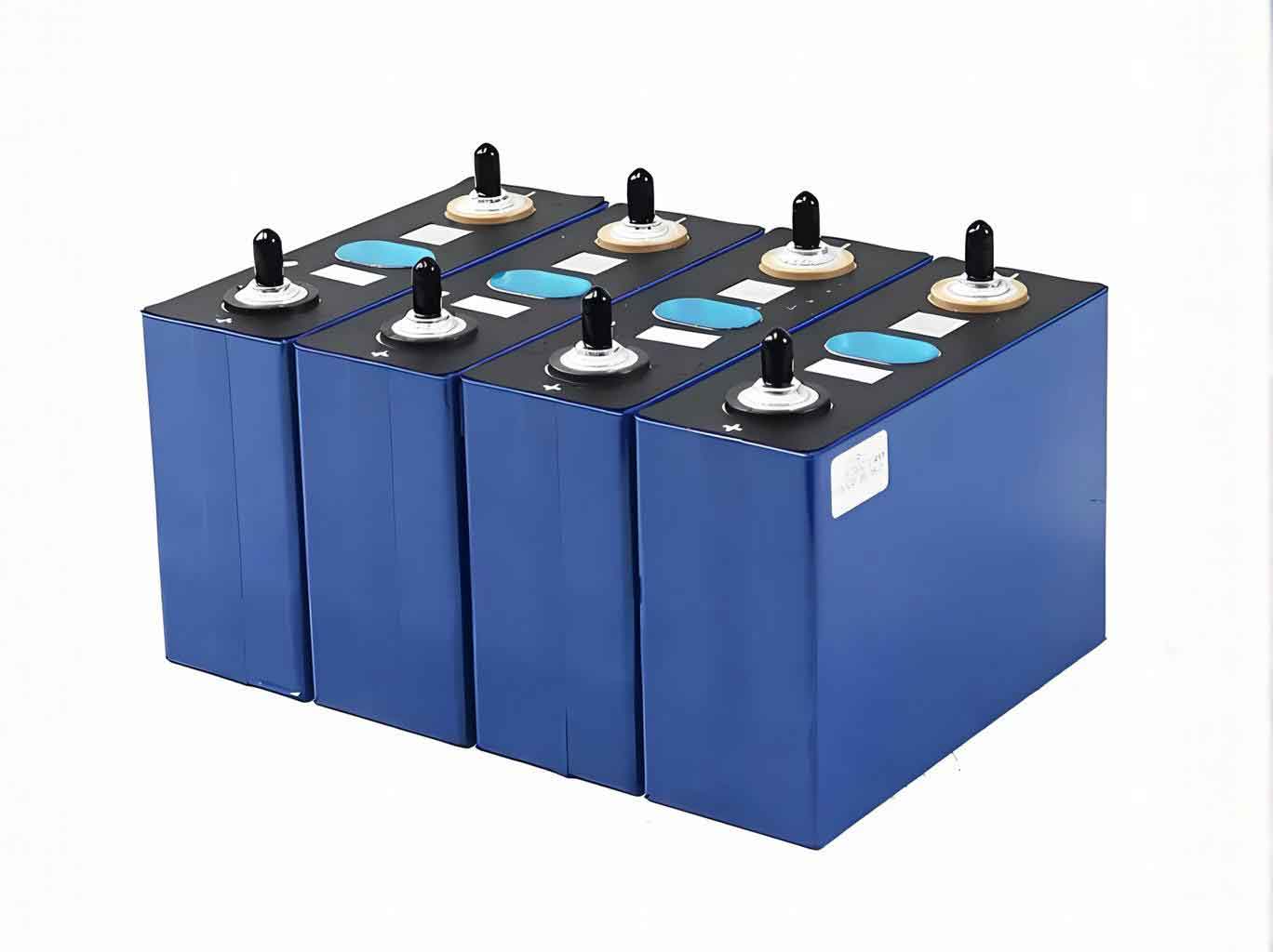
Effective fire suppression for such hazards requires agents that not only extinguish flames rapidly but also provide sustained cooling to halt the chain reaction of thermal runaway in adjacent energy storage cells. While water-based systems offer excellent cooling, they pose risks of electrical short circuits, collateral damage to equipment, and are challenging to maintain in freezing climates. This has driven the search for clean, electrically non-conductive agents. Perfluoro-2-methyl-3-pentanone (C6F12O, commonly known as Novec 1230 or “full-fluorinated hexanone”) has emerged as a promising Halon and HFC alternative. Its properties include high thermal capacity, low toxicity, zero ozone depletion potential, and a short atmospheric lifetime. Yet, its efficacy in suppressing LiFePO4 energy storage cell fires and, crucially, inhibiting thermal runaway propagation has been a subject of debate, lacking comprehensive design standards for this specific application.
Based on extensive research and practical engineering experience, this article presents an optimized fire suppression strategy for LiFePO4 energy storage cell cabins using perfluoro-2-methyl-3-pentanone. The strategy moves beyond traditional application methods by synergistically combining “local application” and “total flooding” principles. The core findings are derived from scaled model tests and have been successfully implemented in a real-world project. The system’s design parameters, operational logic, and backup measures are discussed in detail.
Fire Hazard Analysis and Agent Selection Rationale
The fire dynamics within an energy storage cell cabin are unique. Failure typically initiates in the weakest single energy storage cell within a module due to manufacturing defects or aging. Upon detection of thermal runaway (via smoke, temperature, or gas sensors), the Battery Management System (BMS) disconnects the entire cabin from the grid. Subsequently, fire propagation is primarily driven by thermal radiation from the initially failing energy storage cell to its neighbors, causing them to overheat and enter thermal runaway. Therefore, an ideal suppression system must act with extreme speed during the initial single-energy storage cell failure stage and maintain a protective environment to prevent cascading failure.
The key requirements for the fire suppression agent are:
1. Fast Flame Knockdown: Quickly extinguish the flames from ejected flammable gases.
2. High Heat Absorption (Cooling): Reduce the temperature of the failing energy storage cell and, more importantly, its surrounding cells below the thermal runaway threshold.
3. Inerting/Chain Reaction Inhibition: Interrupt the free radical chain reactions of combustion.
4. Electrical Non-Conductivity & Cleanliness: Cause no secondary damage to the untouched energy storage cells and electrical components.
5. Environmental Acceptability: Have a low global warming potential (GWP).
Perfluoro-2-methyl-3-pentanone operates through a powerful physical cooling mechanism, supplemented by chemical interference. Its high liquid heat capacity and latent heat of vaporization allow it to absorb significant energy as it vaporizes, dramatically cooling the fuel and surrounding air. The chemical mechanism involves the thermal decomposition of the molecule, releasing fluorine radicals (e.g., CF3•) that scavenge the high-energy H• and OH• radicals essential for sustaining combustion, thereby breaking the chain reaction.
Comparative studies have quantified its performance against other agents like water mist, HFCs, and ABC dry powder for lithium-ion battery fires. Results consistently show that while water is superior for sustained cooling, perfluoro-2-methyl-3-pentanone offers the best combination of rapid flame extinguishment and cooling among the clean gaseous agents. Its performance can be summarized relative to key parameters:
| Suppression Agent | Flame Extinction Speed | Cooling Capacity | Re-ignition Risk | Secondary Damage |
|---|---|---|---|---|
| Water Mist | Good | Excellent | Very Low | High (Short Circuit, Corrosion) |
| Perfluoro-2-methyl-3-pentanone | Excellent | Good | Medium* | Very Low |
| HFC-227ea | Good | Fair | High | Low |
| ABC Dry Powder | Excellent | Poor | High | High (Contamination, Corrosion) |
*Risk is highly dependent on application strategy and concentration maintenance, as discussed later.
Development of an Optimized Suppression Strategy: Model Testing
Previous isolated tests using either pure “total flooding” (uniform dispersion throughout the cabin) or “local application” (direct discharge onto a specific module) yielded incomplete success. The total flooding approach often failed to maintain a high enough concentration at the core of a burning battery cluster to prevent re-ignition. The local application approach extinguished surface flames but could not sustain cooling, allowing thermal runaway to resume. This indicated the need for a hybrid strategy.
We hypothesized a two-phase strategy: Phase 1 (Rapid Localized Knockdown): Direct a high flow of agent precisely at the incipient fire cluster to achieve a very high local concentration, extinguishing flames and initiating cooling. Phase 2 (Sustained Inerting & Cooling): Maintain an elevated minimum concentration in the entire cabin volume through intermittent agent injections (“pulse discharges”) to prevent re-ignition and inhibit thermal runaway propagation in neighboring cells.
A full-scale model test was designed to validate this hypothesis and derive critical design parameters.
Test Model and Setup
A test cabin (3.5m L x 2.45m W x 3.2m H) housed a single, full-size battery cluster mockup. The cluster contained one actual battery module with five 150Ah LiFePO4 energy storage cells, with one designated as the “trigger” energy storage cell. The remaining module positions and other clusters in the rack were represented by inert dummy boxes of identical dimensions. The trigger energy storage cell was fitted with a heater and surrounded by thermocouples monitoring its temperature and that of adjacent cells/modules.
The perfluoro-2-methyl-3-pentanone system was configured with six fine-mist nozzles positioned strategically at the rear side of the target cluster, enabling a directed “local application” discharge. The system was programmable for timed pulse discharges.
Test Procedure and Key Observations
- Ignition: The heater was activated on the trigger energy storage cell at t=0.
- Alarm & Gas Release: At t=13m 23s, gas sensors alarmed. At t=25m 15s, the cell vented copious flammable gas, and the heater was shut off.
- Fire & Suppression: The gas was ignited at t=25m 43s, creating an open flame. At t=28m 17s, the suppression system was manually activated.
- Phase 1: A 15-second continuous discharge from the cluster nozzles commenced at t=28m 21s, extinguishing the open flame almost instantly.
- Phase 2: Following the initial discharge, the system entered a pulsed mode, injecting short bursts of agent at regular intervals for a total duration of 20 minutes.
Test Results and Quantitative Analysis
The test was a definitive success. Only the single trigger energy storage cell underwent complete thermal runaway. All adjacent energy storage cells remained intact, functional, and their voltages stable. No re-ignition occurred during the 20-minute protected period.
The temperature data was highly informative. The temperature \( T \) of a neighboring cell can be modeled as a function of heat input from the failing cell and cooling from the agent:
$$
T(t) = T_{ambient} + \int_0^t \left( \frac{Q_{rad}(\tau) – Q_{cool}(\tau, C_{agent})}{C_{th}} \right) d\tau
$$
where \( Q_{rad} \) is the radiative heat flux, \( Q_{cool} \) is the cooling power from the vaporizing agent (dependent on local agent concentration \( C_{agent} \)), and \( C_{th} \) is the thermal mass. The data showed that after flame extinguishment, temperatures initially dropped but began to rise again as the agent dissipated, confirming the need for sustained concentration. The pulsed injections successfully countered this temperature rise.
The total agent used was 38.2 liters. The cabin volume was approximately 27.4 m³. The average density of air is about 1.2 kg/m³. We can estimate the average concentration \( C_{avg} \) achieved over the suppression period, considering the agent’s liquid density \( \rho_{agent} \approx 1.6 \) kg/L:
$$
m_{agent} = 38.2 \, \text{L} \times 1.6 \, \text{kg/L} = 61.12 \, \text{kg}
$$
$$
C_{avg} \approx \frac{m_{agent}}{V_{cabin} \cdot \rho_{air}} = \frac{61.12 \, \text{kg}}{27.4 \, \text{m}^3 \times 1.2 \, \text{kg/m}^3} \approx 1.86 \, \text{or} \, 186\%
$$
This high number reflects the fact that the agent is stored as a liquid and vaporizes, and the calculation is a rough mass-to-mass ratio. More critically, we can estimate the initial local concentration from the first 15-second pulse. If we assume 40% of the total agent was discharged in the first pulse (≈24.5 kg), the instantaneous local concentration in the cluster zone would be extremely high, facilitating rapid knockdown. The subsequent pulses maintained the whole-cabin concentration well above the typical design concentration for Class A fires (4-6%).
The key derived parameters from the test are summarized below:
| Parameter | Value / Description | Significance |
|---|---|---|
| Critical Response Time | < 3 minutes from open flame | System must activate before propagation to adjacent cells. |
| Phase 1 Discharge Duration | 15 seconds (continuous) | Ensures high local concentration for flame knockdown. |
| Phase 2 Strategy | Intermittent pulsed discharge | Maintains protective concentration without needing continuous full flow. |
| Total Suppression (Soak) Time | 20 minutes | Required duration to ensure thermal stability post-ignition. |
| Effective Minimum Concentration | Significantly > 6% v/v | Required to suppress LiFePO4 thermal runaway, not just flame. |
Engineering Application: System Design and Implementation
The validated strategy was deployed in a large-scale “Wind-Solar-Storage” integration project located in a region with extreme winter temperatures (down to -40°C), making water-based systems impractical. The energy storage facility comprised 88 prefabricated cabins, each with a capacity of 14 MW/28 MWh.
Cabin Configuration and Fire Hazard
Each standard 40ft cabin (12.2m x 2.4m x 2.8m) contained 10 battery clusters. Each cluster comprised 33 modules, and each module contained 24 individual 150Ah LiFePO4 energy storage cells. In total, each cabin housed approximately 7,920 energy storage cells. The fire load and potential for cascading thermal runaway were substantial.
Perfluoro-2-Methyl-3-Pentanone System Design
Each cabin was equipped with an independent fire suppression system based on the hybrid strategy. The design adhered to the following principles:
1. Zoned Local Application: Each of the 10 battery clusters was defined as a separate protection zone. Each zone was fitted with a dedicated solenoid control valve feeding a network of discharge nozzles (12 nozzles per cluster, strategically aimed).
2. Fast, Targeted Detection and Actuation: Each cluster was monitored by multiple sensors (temperature, gas). Upon confirmation of a fire within a specific cluster, the control system:
- Activated the central alarm.
- Sent a trip signal to the cabin’s BMS for electrical isolation.
- Opened only the control valve for the affected cluster.
This ensured agent was concentrated on the fire origin, maximizing efficiency.
3. Two-Phase Discharge Protocol:
- Phase 1 (Knockdown): Upon valve opening, the nozzles in the affected cluster discharged agent continuously for a 15-second period.
- Phase 2 (Inerting): The system then switched to a pre-programmed pulsed discharge sequence for the same cluster, maintaining a protective atmosphere for 20 minutes.
The mass of agent \( m_{inj}(t) \) injected over time can be described as:
$$
m_{inj}(t) = m_{pulse} \cdot \sum_{n=0}^{N} \delta(t – n \cdot \Delta t)
$$
where \( m_{pulse} \) is the agent mass per pulse, \( \Delta t \) is the time interval between pulses, and \( N \) is the total number of pulses over the soak time.
4. Sizing and Concentration: The total agent quantity per cabin was sized to achieve the required high concentration, factoring in cabin free volume, temperature, and altitude corrections. The design quantity was set at 90 liters (approximately 144 kg) of liquid perfluoro-2-methyl-3-pentanone. This corresponds to a design concentration \( C_{design} \) calculated as:
$$
C_{design} = \frac{m_{agent}}{V_{cabin-free} \cdot \rho_{air}} \times 100\% \quad \text{(adjusted for temperature/pressure)}
$$
This designed concentration was consistent with the effective concentration demonstrated in the model test.
5. System Components: The system consisted of a central storage unit with pump assembly (for reliable liquid transfer), a main distribution manifold, ten zone control valves (solenoid-operated), and a network of DN15 main pipes and DN8 flexible hoses to the nozzles.
Backup and Emergency Measures
Despite the robustness of the primary system, engineering prudence dictated the inclusion of backup measures.
1. Agent Reserve: Following best practices for fixed fire suppression systems, a 100% reserve of agent (90 liters) was maintained on-site as a shared resource for the entire facility, allowing for recharge after a discharge event.
2. Emergency Water Deluge Interface: Recognizing the possibility of a failure in the primary system or a fire growing beyond its design basis (e.g., simultaneous ignition in multiple clusters), a passive safety net was installed. Each cabin was equipped with a semi-fixed open deluge sprinkler system. This system consisted of open sprinkler heads in the cabin ceiling and an external fire department connection (FDC). In a severe emergency, firefighters can connect a hose to the FDC, flooding the cabin with water. While this would likely result in total loss of the energy storage cell equipment, it serves as a final barrier to prevent conflagration and protect surrounding assets. This system remains dry and freezeproof under normal conditions.
Conclusion
The fire risk associated with lithium iron phosphate energy storage cell cabins is a critical challenge for the renewable energy transition. Perfluoro-2-methyl-3-pentanone presents a viable suppression agent due to its clean, fast-acting, and cooling properties. However, traditional gas application methods are insufficient to address the persistent thermal runaway threat.
The proposed and validated hybrid strategy—combining an initial high-intensity local application for flame knockdown with a sustained total flooding concentration maintained via pulsed discharges—proves effective. This approach addresses the unique fire progression in energy storage cell arrays: rapid intervention at the source and prolonged inhibition of propagation. The derived parameters, such as the critical sub-3-minute response, 15-second initial discharge, 20-minute soak time, and the need for a design concentration significantly higher than standard values, provide essential guidance for engineers.
The successful implementation in a harsh climate project demonstrates the practical feasibility of this system. The integration of a fail-safe water deluge interface adds a crucial layer of safety-in-depth. This comprehensive approach, moving from model testing to parameter derivation and finally to detailed engineering design, offers a reliable template for enhancing the safety of containerized lithium iron phosphate energy storage cell installations worldwide.
| Aspect | Traditional Total Flooding | Traditional Local Application | Optimized Hybrid Strategy |
|---|---|---|---|
| Application Focus | Entire cabin volume uniformly | Directly on visible fire seat | Targeted cluster (Local) + Whole cabin (Flood) |
| Strength | Creates inert atmosphere | High direct cooling/knockdown | Combines rapid knockdown with sustained inerting |
| Weakness for Li-ion | Slow to achieve high concentration at fire core; re-ignition risk | Cannot prevent thermal runaway in adjacent cells; cooling not sustained | Higher system complexity; requires precise detection zoning |
| Agent Efficiency | Lower (wasted on entire volume initially) | Higher for initial fire, but fails overall | High (targeted use followed by maintained minimum concentration) |
| Key Requirement | High total agent quantity | Fast detection and aiming | Fast zoned detection + Programmable pulsed discharge |