
Embedded systems have revolutionized the way we approach renewable energy harvesting. In this thesis, I present a comprehensive study and implementation of an automatic tracking system for solar panels based on the ARM11 microprocessor. The proposed system integrates solar photovoltaic panels, photoresistors, photodiodes, stepper motors, a three-dimensional sliding bracket, and an ARM11 processor to achieve efficient and cost-effective solar tracking. By leveraging the biological principle of light detection in insects with three simple eyes, the system compares the resistance values of multiple photoresistors and controls motor drivers through a single ARM11 unit, enabling multiple solar panels to maintain an optimal angle relative to the sun. This design not only enhances solar energy utilization but also significantly reduces hardware and operational costs. Through extensive experiments, the system demonstrates high stability, precision, networking capability, low power consumption, and user-friendly operation.
1 Introduction
The global energy landscape is heavily dependent on non-renewable resources such as oil, natural gas, coal, and nuclear fuels, which account for approximately 90% of total energy consumption. The inevitable depletion of these resources poses a severe threat to sustainable development and human well-being. Among renewable energy sources, solar energy stands out due to its abundance and environmental friendliness. Solar photovoltaic (PV) power generation has emerged as one of the most promising applications of solar energy. However, the intermittent nature of sunlight and its varying intensity and direction throughout the day necessitate efficient tracking mechanisms to maximize energy capture.
Traditional solar panel installations are often fixed, which results in suboptimal energy collection. Research indicates that a solar tracking system can improve energy reception by approximately 35% compared to a fixed installation. Therefore, developing a robust, low-cost, and intelligent tracking system is of paramount importance. The system presented in this thesis addresses the limitations of conventional trackers by employing an embedded ARM11 processor, a set of photoresistors arranged according to a bio-inspired principle, and a mechanical sliding支架 that enables dual-axis tracking. This system is designed to be modular, expandable, and capable of controlling multiple solar panels simultaneously, thus realizing the concept of “one master, multiple slaves” in a distributed photovoltaic array.
2 Overall System Design
2.1 Biological Principle of Three-Eye Insect Light Recognition
Insects such as locusts possess two compound eyes and three simple eyes (ocelli). Experiments have shown that these three ocelli enable the insect to detect light direction and adjust its body orientation accordingly. When the two compound eyes are covered, the insect can still find a light source using its three ocelli. If one of the ocelli is covered, the insect struggles and repeatedly bumps into the obstacle, indicating that all three ocelli work together to locate the center of the light. The working principle is as follows: the insect first compares the light intensity received by the left and right ocelli, adjusting its body horizontally until both intensities are equal. Then it compares the lower ocellus with either of the upper ocelli, adjusting its body vertically until all three ocelli receive equal illumination. This biological strategy is elegantly simple and can be translated into a solar tracking algorithm.
In my design, I employ three photoresistors arranged in an equilateral triangle configuration on the solar panel. Two photoresistors are placed symmetrically along the east-west direction, and one is placed at the top center. By comparing the resistance values of these sensors, the controller can determine the angular error in both azimuth and elevation and drive the stepper motors to correct it.
2.2 Basic Principles of the Solar Panel Tracking System
The automatic tracking system uses an ARM11 processor, motor driver chips, and auxiliary circuits. The workflow is as follows: first, the ARM11 reads the resistance values of the left and right photoresistors. The difference between these values is calculated and processed. Based on the sign and magnitude of the difference, the controller sends commands to the corresponding motor driver to rotate the solar panel until the two resistance values are equal, indicating that the panel is aligned in the horizontal plane. Then, the system compares the resistance of the upper photoresistor with either the left or right one. Similarly, the vertical motor adjusts the tilt until these values are equal. At this point, the solar panel is perpendicular to the incident sunlight, maximizing energy absorption.
The mechanical transmission mechanism is critical for tracking accuracy and reliability. In this system, the horizontal rotation is driven by a 57 series two-phase stepper motor, while the vertical tilt is controlled by a 39 series two-phase stepper motor. These motors provide precise positioning and high torque, ensuring smooth operation even under wind loads.
2.3 Overall Embedded System Architecture
The hardware platform centers on the Samsung S3C6410, an ARM11 application processor. This chip features a 16/32-bit RISC architecture, a rich set of peripherals, and low power consumption. The system includes modules for information processing, information storage, interfacing, human-machine interaction, automatic tracking, networking, and power management. The software platform is built on embedded Linux, with application programs developed in C and using the Qtopia graphical user interface framework. The overall block diagram is summarized in Table 1.
| Module | Function | Key Components |
|---|---|---|
| Information Processing | Central control, algorithm execution | ARM11 S3C6410 |
| Information Storage | Program code, bootloader, data logging | NAND Flash, DDR SDRAM |
| Interfaces | Serial, USB, LCD, network | MAX3232, USB connectors, DM9000 |
| Human-Machine Interaction | Touch screen display and control | VPG12864T LCD, ADS7843 touch controller |
| Automatic Tracking | Sun position sensing and motor control | Photoresistors, stepper motors, M542 drivers |
| Networking | Remote monitoring and control | Ethernet, Wi-Fi via USB |
| Power Management | Voltage regulation and battery charging | HBSC-101P controller, buck converters |
The control algorithm can be expressed mathematically. Let \(R_L\) and \(R_R\) be the resistances of the left and right photoresistors. The horizontal error signal is defined as:
$$ e_h = R_L – R_R $$
Similarly, let \(R_U\) be the resistance of the upper photoresistor. The vertical error signal is:
$$ e_v = R_U – \frac{R_L + R_R}{2} $$
The motor control law is a simple on-off controller with a dead zone:
$$ u_h = \begin{cases} +1 & \text{if } e_h > \Delta \\ -1 & \text{if } e_h < -\Delta \\ 0 & \text{otherwise} \end{cases} $$
where \(\Delta\) represents the tolerance threshold. The same law applies to \(u_v\) using \(e_v\). This controller is easy to implement and robust against noise.
3 Hardware Design
3.1 Information Processing Module
The S3C6410 processor is the heart of the system. It is based on the ARM1176JZF-S core, which includes 16KB instruction cache, 16KB data cache, and a floating-point co-processor. The processor runs at 533 MHz (up to 667 MHz) and supports a 64/32-bit internal bus architecture. It features a multi-format video codec (MFC), 2D/3D graphics acceleration, and a wide range of peripherals including USB, UART, I2C, SPI, and GPIO. The S3C6410 supports multiple boot modes, including NAND Flash and SD card boot, making it highly flexible for embedded applications.
3.2 Information Storage Module
Two types of memory are used: DDR SDRAM for runtime program execution and NAND Flash for persistent storage. Two K4X1G163PE DDR SDRAM chips are organized in parallel to form a 128MB, 32-bit memory system. The NAND Flash is a Samsung K9F2G08U with 128MB capacity, used to store the bootloader, Linux kernel, file system, and user applications. Table 2 summarizes the memory configuration.
| Memory Type | Model | Capacity | Data Bus Width | Purpose |
|---|---|---|---|---|
| DDR SDRAM | K4X1G163PE | 128 MB (2×64 MB) | 32-bit | Runtime data, stack, heap |
| NAND Flash | K9F2G08U | 128 MB | 8-bit I/O | Bootloader, kernel, file system |
3.3 Interface Modules
The UART interface is implemented using a MAX3232 chip for RS-232 level conversion. The system provides four UART channels, with UART0 dedicated to debug communication with a host PC. The USB interface includes one Host port and one OTG port. The Host port allows connection of USB devices such as keyboards, mice, and Wi-Fi adapters, while the OTG port enables communication with a PC for debugging and firmware updates. The LCD interface supports TFT panels up to 720×480 resolution, with a built-in touch screen controller (ADS7843).
3.4 Human-Machine Interaction Module
The user interface is provided by a VPG12864T dot-matrix LCD module (128×64 pixels). It supports 16×16 Chinese characters and is controlled by a T6963C controller. The S3C6410’s LCD controller interfaces with this module through a parallel bus. The touch screen interface is based on the ADS7843 chip, which converts analog touch coordinates into digital values for the processor.
3.5 Automatic Tracking Module
This module is the core of the system. It consists of photoresistors, stepper motors (57HS22 and 39HS02), M542 drivers, a HBSC-101P controller, and a stereo sliding bracket. The photoresistors are arranged as shown in the following figure; the arrangement follows the three-eye insect principle.
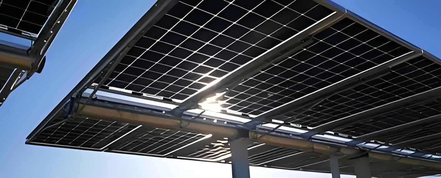
The light sensing circuit uses a bridge configuration, as depicted in Figure 3.1. The output voltage \(V_{out}\) is proportional to the difference in resistance between two adjacent photoresistors. This differential measurement reduces the influence of ambient light variations and enhances noise immunity.
The stepper motors provide precise angular movements. The 57HS22 motor is used for horizontal rotation (azimuth), while the 39HS02 motor controls vertical tilt (elevation). The M542 driver is a subdivision driver that supports both pulse/direction and dual-pulse modes. It also features a semi-current reduction mode to reduce heating and power consumption when the motor is idle.
The stereo sliding bracket is designed to support the solar panel while allowing smooth rotation in two axes. The design incorporates the geometric principle of the circumcenter, incenter, and centroid, ensuring balance and minimizing friction. A custom sliding balance controller with a double-wheel mechanism reduces friction and protects the motors from excessive torque.
3.6 Network Module
The network interface is based on the DM9000 Ethernet controller, which supports 10/100 Mbps Ethernet. The DM9000 communicates with the S3C6410 via a 16-bit data bus and provides an interrupt signal to the processor. Wireless connectivity can be added through a USB Wi-Fi adapter, allowing remote monitoring and control of the solar panel system.
3.7 Power Management
The system accepts a 12V DC input, which is regulated to 5V and 3.3V using switching regulators. The HBSC-101P controller manages the charging of the storage battery from the solar panel output and ensures stable DC power for the system. The power architecture is summarized in Table 3.
| Voltage Rail | Source | Application |
|---|---|---|
| 12V DC | External adapter / battery | Input power |
| 5V | Switching regulator | USB, camera, motor drivers |
| 3.3V | LDO / switching regulator | S3C6410 I/O, memory, LCD |
| 1.4V | Dedicated regulator | S3C6410 core |
4 Software Design
4.1 Embedded Operating System Selection
After comparing several real-time operating systems (VxWorks, μC/OS-II, eCos, and Linux), I selected Linux as the embedded OS for the solar panel control system. Linux is open-source, has strong networking capabilities, supports a wide range of processors, and offers excellent stability and portability. The kernel is highly configurable and can be tailored to the limited resources of an embedded system. Additionally, Linux provides a POSIX API, which simplifies multi-threaded application development.
4.2 Linux Operating System Porting
Porting Linux to the S3C6410 board involves several steps: setting up a cross-development environment, configuring the bootloader, porting the kernel, and creating a root file system.
The cross-compilation toolchain used is arm-linux-gcc-4.5.1, which supports ARMv6 architecture with VFP. The bootloader is Supervivi, which initializes the hardware, sets up the memory, and loads the Linux kernel from NAND Flash. The kernel version used is 2.6.36. The configuration process involves modifying the kernel Makefile to set the cross-compiler, enabling device drivers for the S3C6410 (such as NAND Flash, DM9000, LCD, and touch screen), and disabling unnecessary features to reduce kernel size.
The root file system is created using Busybox. A cramfs file system is generated because it is compressed and suitable for read-only embedded environments. The required directory structure includes /bin, /sbin, /usr, /dev, /etc, /lib, /proc, /tmp, and /home. Key configuration files such as inittab, rcS, and fstab are created to initialize the system environment.
4.3 Device Driver Development and Porting
4.3.1 USB Driver
The S3C6410 has an internal USB host controller compliant with OHCI. The driver provided in the Linux kernel was modified for the S3C6410 by removing PCI-related code, setting the base address to 0x49000000, configuring the interrupt, and setting the number of root hub ports to 2. After recompiling the kernel with USB support enabled, the host port can detect and communicate with USB devices.
4.3.2 DM9000 Network Driver
The DM9000 driver was obtained from the manufacturer and modified according to the hardware design. Key changes included setting the base address to 0x20000000 (corresponding to nGCS4), configuring the bus width, and assigning the correct interrupt number (EINT2). After enabling DM9000 support in the kernel configuration, the network interface functioned properly.
4.3.3 LCD and Touch Screen Drivers
The LCD driver uses the Linux framebuffer interface. The initialization function configures the LCD controller registers to set resolution and color depth. The fb_info structure is populated with operations for reading/writing the framebuffer, memory mapping, and I/O control. The touch screen driver for ADS7843 was implemented as a character device driver. It provides read, poll, ioctl, and fasync operations. The driver uses an interrupt to detect touch events and converts analog voltages to X/Y coordinates.
4.4 Application Development
The application software is built on the Qtopia platform, which provides a rich graphical user interface for embedded Linux. The system uses multi-threading to handle concurrent tasks: a main thread for user interaction, a tracking thread for reading photoresistor data and issuing motor commands, a network thread for remote communication, and a monitoring thread for logging data. The state machine of the tracking controller is shown in Figure 4.1 and can be represented by the following equations.
Let \(T\) be the sampling interval (20 minutes for horizontal adjustment, 2 weeks for vertical adjustment). At each sampling instant \(k\), the controller computes:
$$ e_h(k) = R_L(k) – R_R(k) $$
$$ e_v(k) = R_U(k) – \frac{R_L(k)+R_R(k)}{2} $$
The motor commands are:
$$ m_h(k) = K_h \cdot \mathrm{sgn}(e_h(k)) \cdot \mathbf{1}_{\{|e_h(k)|>\Delta_h\}} $$
$$ m_v(k) = K_v \cdot \mathrm{sgn}(e_v(k)) \cdot \mathbf{1}_{\{|e_v(k)|>\Delta_v\}} $$
where \(K_h\) and \(K_v\) are the step counts per unit resistance difference, and \(\Delta_h\), \(\Delta_v\) are dead zones to prevent oscillation. The system also incorporates a manual mode through the touch interface, allowing the user to override automatic tracking.
5 System Testing and Result Analysis
5.1 Test Environment
The hardware test environment consists of the S3C6410 target board, an LCD display, a network connection, serial cables, a JTAG interface, the stereo sliding bracket, stepper motors, and the solar panel. The host machine runs Ubuntu Linux with the cross-compilation toolchain. The system is powered by a 12V battery charged through the HBSC-101P controller.
5.2 Hardware Testing
I first tested the power supply modules to ensure correct voltage levels. Then, I verified the minimal system (ARM11 + memory + serial) by running a simple “hello world” program. After that, each peripheral (UART, USB, LCD, network) was tested individually. Table 4 lists the test results.
| Peripheral | Test Method | Result |
|---|---|---|
| UART | Loopback with PC | Data transmitted and received correctly |
| USB | Mount a USB flash drive | Device detected and read/write successful |
| LCD | Display color patterns | All colors displayed without defects |
| Touch Screen | Calibration test | Coordinates mapped accurately |
| Ethernet | Ping server | 100% packet success |
5.3 Software Testing
Software testing included bootloader, kernel, file system, and application layers. I used GDB for debugging. The “hello world” test was transferred via TFTP, USB, serial, and NFS to verify all file transfer paths. The tracking algorithm was tested under various sunlight conditions. The system successfully adjusted the solar panel to face the sun, with a response time of a few seconds for horizontal alignment and a few minutes for vertical alignment due to the larger gear ratio.
5.4 Problems Encountered
Problem 1: The motor rotated too much in each step. This was caused by an excessively high pulse frequency. Reducing the frequency in the driver settings solved the issue.
Problem 2: The sliding bracket experienced high friction. Adding a double-wheel sliding balance mechanism at the contact points reduced friction and improved smoothness.
Problem 3: The sunlight was not centered on the solar panel. The positions of the photoresistors were not symmetric. After fine-tuning their placement, the alignment became correct.
5.5 Experimental Results
I compared the proposed system with conventional tracking methods. Table 5 shows the positioning accuracy and the improvement in battery charge compared with a fixed solar panel.
| Tracking Method | Positioning Accuracy (%) | Charge Improvement (%) |
|---|---|---|
| Clock-based | 76.13 | 20.73 |
| Pressure-difference | 81.70 | 23.50 |
| Controlled-release | 86.30 | 22.63 |
| Photoresistive (proposed) | 93.90 | 39.83 |
The proposed photoresistive tracking system achieved the highest positioning accuracy and the largest improvement in energy storage. The experimental setup is shown in Figure 5.1. The system maintained stable tracking throughout the day, even under partially cloudy conditions, due to the differential measurement scheme.
The power consumption of the entire controller is low because the motors only operate periodically. During idle periods, the controller, sensors, and user interface consume less than 1W. The system’s modular design allows expansion to multiple solar panels, each with its own local motor driver, all coordinated by a single ARM11 processor.
6 Conclusion and Future Work
6.1 Summary
In this thesis, I have successfully designed and implemented an embedded automatic tracking system for solar panels based on the ARM11 processor S3C6410. The key contributions of this work are as follows:
- Introduced the biological principle of three-eye insects for light direction detection and applied it to solar tracking using three photoresistors arranged in an equilateral triangle.
- Designed a stereo sliding bracket and a sliding balance controller that ensure smooth two-axis rotation, low friction, and high mechanical stability.
- Implemented a modular hardware architecture with ARM11 as the central controller, capable of managing multiple solar panels simultaneously through a single processor.
- Ported the embedded Linux operating system, developed device drivers for USB, Ethernet, LCD, and touch screen, and created a multi-threaded application with a graphical user interface based on Qtopia.
- Demonstrated through experiments that the proposed tracking system improves solar energy utilization by approximately 40% compared to fixed panels, with higher accuracy than traditional clock-based or pressure-difference systems.
6.2 Future Research Directions
Although the system meets its design goals, there are several areas for future improvement:
- Optimizing the hardware layout and shielding to enhance electromagnetic interference resistance.
- Adding a weatherproof enclosure to protect the system from rain, dust, and extreme temperatures.
- Enhancing the networking capabilities to support cloud-based monitoring and control of distributed solar panel arrays.
- Integrating the motor driver and charge controller functions directly into the ARM11 board to further reduce cost and complexity.
- Exploring machine learning algorithms for predictive tracking based on historical solar irradiance data.
The proposed ARM-based solar panel control system has broad application prospects in residential, commercial, and industrial settings. Its low cost, high efficiency, and scalability make it an attractive solution for the global transition toward renewable energy.