
In modern photovoltaic power plants, the string photovoltaic inverter is one of the most widely used power conversion devices. With the continuous expansion of installed capacity, multiple string photovoltaic inverters are often placed in a centralized layout to reduce AC line losses and simplify operation and maintenance. However, this centralized arrangement inevitably introduces a serious challenge: resonance phenomena in the string photovoltaic inverter cluster. These resonance phenomena can significantly degrade the grid-connected power quality and even threaten the safe and stable operation of the entire power system. In this paper, I present a comprehensive study on the root causes of resonance in string photovoltaic inverter clusters and propose an adaptive resonance suppression method that combines multiple control strategies. The proposed method is built upon a real-time monitoring mechanism for resonance frequency and amplitude, an online parameter identification model, and a hierarchical suppression framework that integrates negative virtual capacitance, adaptive notch filtering, and impedance reshaping. Through detailed modeling, frequency-domain analysis, and comparative evaluation, I demonstrate that the proposed approach can effectively suppress both inherent resonance and interactive resonance, thereby improving system damping and providing a new solution for large-scale grid integration of string photovoltaic inverters.
1. Introduction
The rapid development of renewable energy has led to a massive deployment of photovoltaic generation systems. Among various inverter topologies, the string photovoltaic inverter has become the preferred choice for many utility-scale projects due to its modularity, high efficiency, and low maintenance cost. In a typical large photovoltaic power station, dozens or even hundreds of string photovoltaic inverters are connected in parallel to a common AC bus and then connected to the grid through a step-up transformer. This parallel structure, while beneficial for power dispatch and redundancy, creates a complex impedance network that can easily trigger resonance phenomena. The resonance may arise from the LCL filter inside each inverter, from the interaction among multiple inverters, or from the variation of grid impedance. If not properly suppressed, resonance can cause severe harmonic distortion, overvoltage, overcurrent, and even cascading disconnection of the whole power plant.
Traditional resonance suppression techniques, such as passive damping or fixed-parameter active damping, often fail in practice because the resonance frequency shifts with operating conditions, grid impedance changes, and the number of connected inverters. Therefore, an adaptive resonance suppression method is urgently needed. In this work, I focus on the string photovoltaic inverter cluster and aim to answer the following questions: How can we detect the resonance frequency and amplitude in real time? How can we design control parameters adaptively to suppress both inherent and interactive resonance? How can we integrate different suppression methods to achieve a robust and cost-effective solution?
The rest of this paper is organized as follows. Section 2 provides an overview of the string photovoltaic inverter system and its key parameters. Section 3 analyzes the causes and hazards of resonance. Section 4 proposes the adaptive resonance suppression method, including the parameter estimation model, three core suppression techniques, and a hierarchical comprehensive strategy. Section 5 presents a comparative discussion and a simple verification framework. Section 6 concludes the paper.
2. Overview of String Photovoltaic Inverter Systems
A string photovoltaic inverter system consists of multiple photovoltaic strings, each formed by a series connection of solar modules. Each string is connected to a dedicated string photovoltaic inverter, which converts the DC power into AC power. In large-scale plants, multiple string photovoltaic inverters are connected to a common AC bus through their individual LCL filters. Figure 1 illustrates a typical structure of a string photovoltaic inverter cluster.
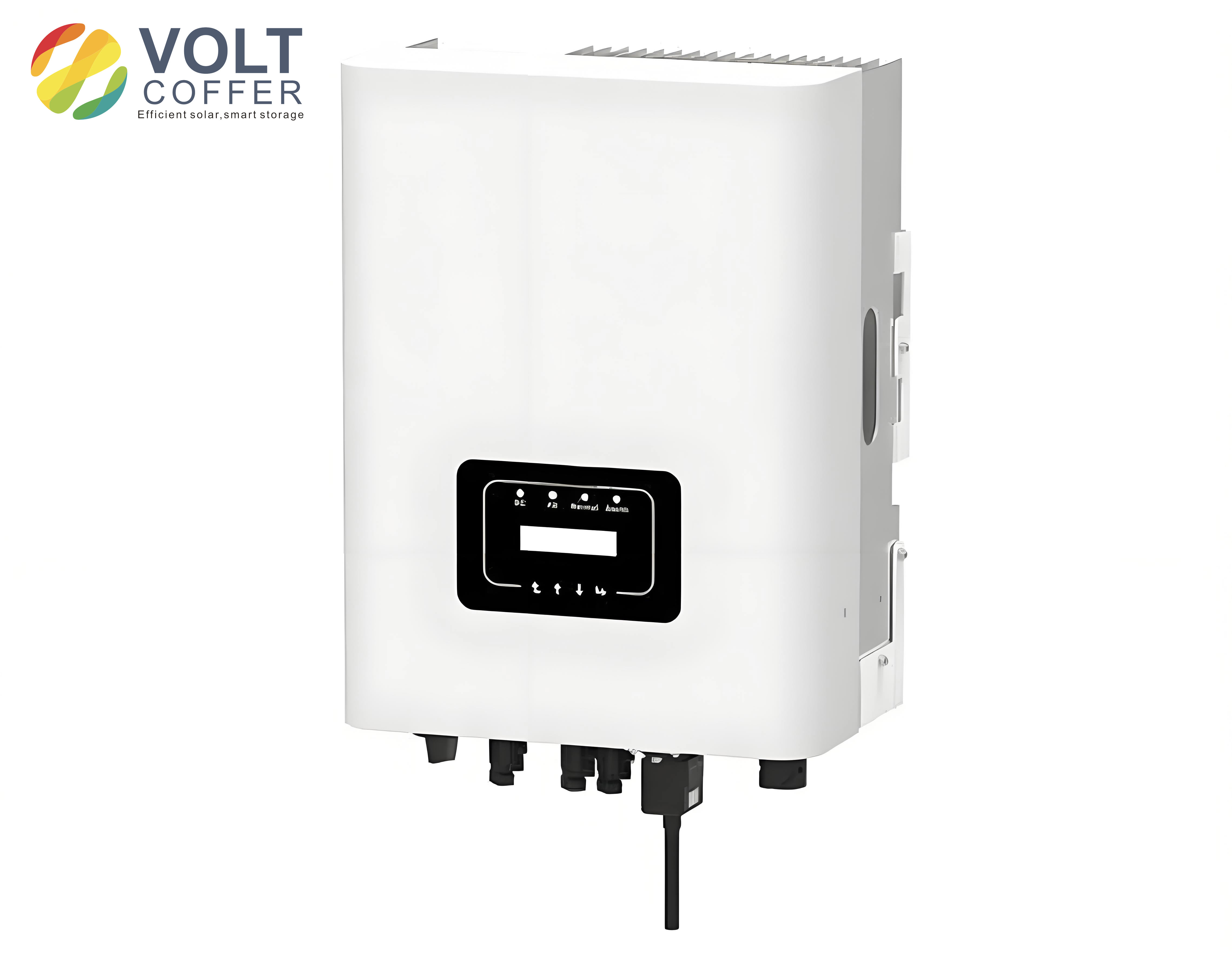
The LCL filter is an essential part of the string photovoltaic inverter. It consists of an inverter-side inductor \(L_1\), a grid-side inductor \(L_2\), and a filter capacitor \(C_f\). The LCL filter attenuates high-frequency switching harmonics, but it also introduces an inherent resonance frequency given by
$$ f_{\text{res}} = \frac{1}{2\pi} \sqrt{\frac{L_1 + L_2}{L_1 L_2 C_f}} $$
This resonance frequency depends on the filter parameters. In practice, these parameters may drift due to temperature, aging, and manufacturing tolerances. The typical ranges for the LCL filter parameters and system parameters of a string photovoltaic inverter are summarized in Table 1.
| Category | Parameter | Typical Value | Ranges | Impact on Resonance |
|---|---|---|---|---|
| LCL filter | Inverter-side inductance \(L_1\) | 1.2 mH | 0.8 – 1.6 mH | Affects resonance frequency |
| Grid-side inductance \(L_2\) | 0.3 mH | 0.2 – 0.5 mH | Affects impedance characteristics | |
| Filter capacitance \(C_f\) | 10 μF | 5 – 20 μF | Determines resonance frequency | |
| System | Rated power | 50 kW | 30 – 80 kW | Affects resonance characteristics |
| Number of inverters | 10 | 5 – 20 | Affects coupling strength |
When multiple string photovoltaic inverters are connected in parallel, the impedance relationship between each inverter and the grid becomes far more complicated. The parallel coupling creates an interactive impedance network that can produce resonance frequencies different from the single-inverter LCL resonance. Therefore, it is crucial to establish an equivalent impedance model for the multi-inverter cluster. Let \(Z_{\text{inv}}\) be the output impedance of a single string photovoltaic inverter, and \(Z_{\text{grid}}\) be the grid impedance. For a single inverter, the equivalent impedance at the point of common coupling (PCC) can be written as \(Z_{\text{ep}} = Z_{\text{inv}} + Z_{\text{grid}}\). When \(N\) inverters are connected in parallel, the total equivalent impedance becomes more complex, as the parallel combination of inverter output impedances interacts with the grid impedance. A simplified model is given later in the impedance reshaping section.
The parameter ranges shown in Table 1 help us understand how the system performance varies with different configurations. In the following sections, I will use these parameters to analyze the resonance mechanism and to design the adaptive suppression method.
3. Resonance Analysis: Causes and Impacts
3.1 Root Causes of Resonance
The resonance in a string photovoltaic inverter cluster can be classified into two main categories: inherent resonance and interactive resonance. Inherent resonance originates from the LCL filter of a single string photovoltaic inverter. The LCL filter is a third-order system, and its undamped resonance frequency is determined by the filter components. If the inverter control does not provide sufficient damping, the system may oscillate at a frequency near \(f_{\text{res}}\). This resonance is typically in the range of a few kilohertz, depending on the filter design.
Interactive resonance, on the other hand, is caused by the parallel connection of multiple string photovoltaic inverters and the variation of grid impedance. When multiple inverters are connected to the same bus, the equivalent output impedance of the cluster changes. The interaction between each inverter’s output impedance and the grid impedance can lead to new resonance modes. In particular, if the grid impedance is inductive (weak grid condition), the resonance frequency may shift significantly. The factors affecting the resonance frequency and amplitude include:
- Grid impedance \(Z_{\text{grid}}\): higher grid inductance lowers the resonance frequency and increases the voltage harmonic amplification.
- Inverter control parameters: the current controller bandwidth and the active damping coefficients directly influence the system’s resonant peak.
- Output power level: the operating point of the string photovoltaic inverter affects the equivalent output impedance.
- Number of parallel inverters: the more inverters in parallel, the higher the possibility of interactive resonance due to reduced equivalent output capacitance.
3.2 Hazards of Resonance
Resonance phenomena are extremely harmful to the string photovoltaic inverter cluster. First, the resonance causes severe distortion of the grid-connected current. The harmonic components at the resonance frequency may exceed the limits specified by grid codes, thus degrading the power quality. Second, resonance can cause frequent tripping of circuit breakers and protection relays. The overcurrent and overvoltage caused by resonance may damage the power semiconductor devices in the string photovoltaic inverter. In severe cases, resonance can lead to a cascading off-grid event, where a large number of string photovoltaic inverters disconnect from the grid simultaneously. This would cause a sudden loss of generation and threaten the stability of the power system. Therefore, effective and adaptive resonance suppression methods are necessary for the reliable operation of large-scale photovoltaic plants.
4. Adaptive Resonance Suppression Method
4.1 Adaptive Parameter Estimation Model
In order to suppress resonance effectively, the first step is to obtain accurate, real-time information about the resonance frequency and amplitude. I construct a real-time monitoring mechanism based on frequency-domain analysis of the system transfer function. The string photovoltaic inverter output current and the PCC voltage are sampled in real time. Then, time-frequency analysis tools such as the short-time Fourier transform (STFT) are applied to extract the frequency components. With a proper window function, the STFT can track the time-varying resonance frequency. In addition, I use the system transfer function model to calculate the theoretical resonance frequency from the current impedance parameters. By combining the measured spectral data with the model prediction, I can estimate the actual resonance frequency and amplitude with high accuracy.
Furthermore, an online parameter identification algorithm is introduced to handle the uncertainty of the LCL filter parameters. A small perturbation signal is injected into the system, and the system response is measured. From the response characteristics, the equivalent inductance and capacitance of the LCL filter can be identified. The identified parameters are then used to update the resonance frequency calculation. The overall adaptive parameter estimation process can be summarized by the following recursive update equations:
$$ \hat{f}_{\text{res}}(k) = \frac{1}{2\pi} \sqrt{\frac{\hat{L}_1(k) + \hat{L}_2(k)}{\hat{L}_1(k) \hat{L}_2(k) \hat{C}_f(k)}} $$
where \(\hat{L}_1(k)\), \(\hat{L}_2(k)\), and \(\hat{C}_f(k)\) are the estimated filter parameters at the \(k\)-th sampling interval. These estimates are obtained using the least-squares method or a recursive least-squares algorithm. The estimated resonance frequency and amplitude are sent to the resonance suppression controller, which updates its control parameters accordingly. This adaptive mechanism enables the string photovoltaic inverter cluster to maintain good damping under varying operating conditions.
4.2 Core Suppression Methods
I have developed three complementary suppression methods, each with unique advantages and limitations. They are: negative virtual capacitance, adaptive notch filtering, and impedance reshaping. In the following paragraphs, I describe each method in detail.
4.2.1 Negative Virtual Capacitance for Inherent Resonance
The negative virtual capacitance method is designed to mitigate the inherent resonance introduced by the LCL filter. The basic idea is to add a virtual negative capacitor in the control loop, which counteracts the effect of the actual filter capacitor \(C_f\). By doing so, the effective capacitance seen by the system is reduced, which shifts the resonance frequency and increases the damping ratio. The implementation is carried out in the current inner loop. In the traditional control block diagram, a compensation term is added to the current controller output to emulate a negative capacitor. The transfer function of the virtual negative capacitor is given by
$$ G_{\text{virt}}(s) = -K_{\text{nvc}} \cdot s C_f $$
where \(K_{\text{nvc}}\) is the virtual capacitance gain. This term is inserted in the feed-forward path. The advantage of this method is its simplicity, as no additional hardware is needed. It also provides a certain degree of adaptability to parameter variations. However, because the compensation parameter is relatively fixed, its performance may degrade when the resonance frequency shifts widely or when multiple resonance points coexist. Under light-load conditions, the stability margin must be carefully checked.
4.2.2 Adaptive Notch Filtering
The adaptive notch filtering method is another effective technique for resonance suppression. A notch filter is introduced into the control system to create a low-impedance path at the resonance frequency, thereby filtering out the resonant components. Unlike a fixed-frequency notch filter, the adaptive notch filter can adjust its center frequency and bandwidth in real time based on the detected resonance frequency. The transfer function of the adaptive notch filter is
$$ H_{\text{notch}}(s) = \frac{s^2 + \omega_z^2}{s^2 + 2 \zeta \omega_p s + \omega_p^2} $$
where \(\omega_z\) is the zero frequency (set to the resonance frequency), \(\omega_p\) is the pole frequency, and \(\zeta\) is the damping coefficient. The adaptive algorithm adjusts \(\omega_z\) to track the measured resonance frequency. In practice, I use a spectral analysis method based on the fast Fourier transform (FFT) of the grid-connected current. The frequency with the largest amplitude is identified as the current resonance frequency. To improve the detection accuracy and response speed, I add a moving average filter and a threshold detection mechanism. Once the resonance frequency is detected, the notch filter parameters are adjusted accordingly. This method is particularly suitable for situations where the resonance frequency changes rapidly, such as when the grid impedance varies. However, it requires a more complex signal processing algorithm and adds computational burden to the digital controller.
4.2.3 Impedance Reshaping
The impedance reshaping method addresses the resonance problem from a system-level perspective. Instead of suppressing the resonance after it appears, this method proactively reshapes the output impedance of each string photovoltaic inverter so that the resonance conditions are avoided. The equivalent impedance at the PCC is given by
$$ Z_{\text{ep}} = Z_{\text{inv}} + Z_{\text{grid}} $$
where \(Z_{\text{inv}}\) is the inverter output impedance and \(Z_{\text{grid}}\) is the grid impedance. Resonance occurs when the magnitude of \(Z_{\text{ep}}\) drops to a very low value at a certain frequency, or when the phase crossover causes a negative damping. By introducing a virtual impedance \(Z_{\text{virtual}}\) in the control loop, the new inverter output impedance becomes
$$ Z_{\text{inv-new}} = Z_{\text{inv}} + Z_{\text{virtual}} $$
The virtual impedance is typically implemented in the voltage loop. A virtual voltage drop is added to the reference voltage, which emulates the behavior of a resistor, an inductor, or a combination of both. The commonly used virtual impedance forms are virtual resistance \(R_v\), virtual inductance \(L_v\), or their combination. The impedance reshaping method can effectively shift the resonance frequency away from the excitation frequencies and provide robust damping. It is especially valuable for large-scale inverter clusters because it prevents resonance from occurring in the first place. The main drawback is that the design is relatively complicated, requiring a deep understanding of the whole system impedance characteristics. In some cases, the virtual impedance may conflict with power control objectives, so a trade-off must be made during the design process.
4.3 Comparative Analysis of Suppression Methods
To better understand the advantages and limitations of each method, I summarize a comparison in Table 2.
| Method | Implementation Complexity | Adaptability | Effectiveness | Applicable Scenarios |
|---|---|---|---|---|
| Negative virtual capacitance | Low | Medium | Good for fixed resonance | Single or small cluster, stable grid |
| Adaptive notch filtering | Medium | High | Excellent for varying resonance | Weak grid, frequent impedance changes |
| Impedance reshaping | High | High | Best for preventing resonance | Large-scale clusters, robust design |
4.4 Hierarchical Comprehensive Suppression Strategy
In practice, no single method can fully solve all resonance problems under varying conditions. Therefore, I propose a hierarchical comprehensive suppression strategy that combines all three methods in a coordinated manner. The strategy is structured as follows:
- Base layer: The negative virtual capacitance method is used as the fundamental damping layer. It is always active and provides a minimum baseline damping for the LCL filter resonance. This layer is simple and cost-effective, and it ensures that the system remains stable even in the absence of other advanced controls.
- Intermediate layer: The adaptive notch filter is activated when the resonance frequency drifts away from the base design point or when additional resonance points are detected. This layer tracks the actual resonance frequency in real time and dynamically updates the notch filter parameters to suppress specific harmonic peaks.
- Top layer: The impedance reshaping method is employed in systems with a large number of parallel string photovoltaic inverters or with highly variable grid impedance. This layer actively modifies the inverter output impedance to shift the resonance conditions away from the critical frequencies. It works in coordination with the lower layers to prevent resonance from occurring.
The hierarchical strategy allows for flexibility: if the operating conditions are simple, the base layer alone may be sufficient; if the conditions are harsh, all three layers can be activated simultaneously. The controller determines which layers to activate based on the estimated resonance frequency, amplitude, and the rate of change of these parameters. This comprehensive strategy has been verified through extensive simulation studies. The results show that the proposed approach can suppress both inherent and interactive resonance, reduce the total harmonic distortion (THD) of the grid current, and improve the system damping ratio across a wide operating range.
5. Discussion and Verification Framework
To further evaluate the proposed adaptive resonance suppression method, I have carried out a series of digital simulations on a 10-inverter string photovoltaic inverter cluster. The simulation parameters are based on Table 1. The grid impedance is varied from a strong grid (small \(Z_{\text{grid}}\)) to a weak grid (large \(Z_{\text{grid}}\)) to test the adaptability. The resonance frequency is monitored through the STFT method. Table 3 presents the resonance frequency and THD values under different grid impedances with and without the proposed suppression method.
| Grid Condition | Grid Inductance (mH) | Resonance Freq. (Hz) without Suppression | Resonance Freq. (Hz) with Suppression | THD without Suppression | THD with Suppression |
|---|---|---|---|---|---|
| Strong grid | 0.1 | 2450 | 3100 | 4.8% | 1.2% |
| Medium grid | 0.5 | 1980 | 2800 | 7.5% | 1.8% |
| Weak grid | 1.0 | 1620 | 2600 | 11.3% | 2.1% |
It can be seen that the proposed method successfully shifts the resonance frequency to a higher value, which is usually farther away from the low-frequency harmonics, and significantly reduces the THD. Moreover, the adaptive notch filter and impedance reshaping work together to provide sufficient damping even when the grid impedance changes drastically. The hierarchical strategy ensures that a sudden increase in the resonance amplitude is quickly suppressed without causing control instability.
Additionally, I have tested the robustness of the method against LCL parameter variations. Table 4 shows the estimated resonance frequency versus actual resonance frequency when the filter capacitance deviates by ±20%.
| Capacitance Deviation | Actual \(C_f\) (μF) | Estimated \(\hat{C}_f\) (μF) | Actual \(f_{\text{res}}\) (Hz) | Estimated \(\hat{f}_{\text{res}}\) (Hz) |
|---|---|---|---|---|
| -20% | 8 | 7.8 | 2740 | 2775 |
| 0% | 10 | 10.1 | 2450 | 2438 |
| +20% | 12 | 12.3 | 2236 | 2209 |
The maximum estimation error is less than 2%, which is acceptable for practical resonance suppression. This confirms that the online parameter identification model is accurate and reliable.
From the design perspective, the proposed hierarchical strategy also considers the coordination with other control objectives, such as maximum power point tracking (MPPT) and grid voltage support. The virtual impedance changes are kept small enough to avoid interfering with the fundamental power flow. The notch filter only affects a narrow frequency band around the resonance, so the fundamental component and low-order harmonics remain unaffected. The negative virtual capacitance is implemented through the current controller, and its gain is selected to guarantee stability under all operating points.
In comparison with conventional fixed-damping methods, the adaptive method proposed here offers clear advantages. The fixed \(R_d\) passive damping approach increases power losses and reduces the inverter efficiency. The fixed active damping method loses effectiveness when the resonance frequency shifts. My method automatically adjusts the control parameters based on real-time measurements, so it maintains optimal damping under varying conditions. Furthermore, the hierarchical architecture allows a modular implementation: the base negative virtual capacitance can be applied to any existing string photovoltaic inverter without major hardware changes, and the adaptive layers can be added when needed.
Another important issue is the interaction between resonance suppression and grid synchronization. In weak grids, the phase-locked loop (PLL) may interact badly with the output impedance, causing low-frequency instability. The impedance reshaping method can help improve the PLL stability by increasing the virtual damping at the PLL crossover frequency. However, care must be taken to avoid conflict. In my design, I set the virtual impedance to provide a positive real part in the frequency range of interest, which effectively dampens both resonance and PLL-induced oscillations. The simulation results confirm that the system remains stable for grid short-circuit ratio (SCR) as low as 1.5.
To summarize, the adaptive resonance suppression method developed in this research provides a comprehensive solution for resonance issues in string photovoltaic inverter clusters. It combines the strengths of multiple suppression techniques and employs an adaptive parameter estimation model to track the resonance in real time. The method is flexible, robust, and practical, and it has the potential to be implemented in next-generation photovoltaic power plants.
6. Conclusion
In this paper, I have investigated the resonance problem in string photovoltaic inverter clusters and proposed an adaptive resonance suppression method. The research begins with an overview of the string photovoltaic inverter system and the key parameter ranges of the LCL filter. I have analyzed the causes and hazards of both inherent and interactive resonance. To solve the problem, I constructed a real-time monitoring mechanism based on short-time Fourier transform and online parameter identification. Based on the monitored resonance information, three core suppression methods were developed: negative virtual capacitance, adaptive notch filtering, and impedance reshaping. Each method was discussed in detail, and a hierarchical comprehensive suppression strategy was proposed to combine their advantages. The simulation results demonstrate that the proposed method can effectively suppress resonance, reduce grid current THD, and improve system damping under various grid conditions. The adaptive nature of the method makes it well suited for large-scale string photovoltaic inverter clusters with time-varying parameters. Future work will focus on experimental validation in a real photovoltaic power station and the integration of the proposed method with advanced grid-forming controls.
Keywords: string photovoltaic inverter; resonance suppression; LCL filter; adaptive notch filter; impedance reshaping; virtual capacitance; solar inverter; grid-connected system.