
The persistent global energy crisis and escalating environmental concerns have rendered the development and utilization of solar energy paramount. Among the plethora of photovoltaic technologies, kesterite thin film solar panels based on Cu2ZnSn(S,Se)4 (CZTSSe) absorbers stand out due to their compelling advantages: earth-abundant and low-toxic constituents, a tunable direct bandgap (∼1.0–1.5 eV), a high absorption coefficient (>104 cm–1), and a theoretically high power conversion efficiency (PCE) of approximately 33%. While the current certified record PCE for CZTSSe thin film solar panels stands at 12.6%, achieved via vacuum-based processes, solution-based fabrication methods offer a highly promising alternative route. These non-vacuum approaches are celebrated for their simple operation, high material utilization, low cost, and exceptional suitability for large-area, roll-to-roll manufacturing—key attributes for the future commercialization of thin film solar panels.
From our perspective in the laboratory, navigating the landscape of solution processing for CZTSSe is both challenging and exciting. The journey typically begins with dissolving metal and chalcogen precursors in a suitable solvent system to form an ink. This ink is then deposited onto a substrate—often molybdenum-coated soda-lime glass—using techniques like spin-coating, spray coating, or doctor blading. The deposited wet film undergoes a thermal treatment, first to remove solvents and organic residues (pre-annealing), and then a critical high-temperature selenization or sulfurization step under a chalcogen atmosphere. This final step induces grain growth, densification, and crystallization into the desired kesterite phase, ultimately forming the photoactive absorber layer for thin film solar panels. The complete device is finished by depositing a thin CdS buffer layer (typically via chemical bath deposition), a transparent conductive oxide (like i-ZnO/ITO), and metal grid contacts.
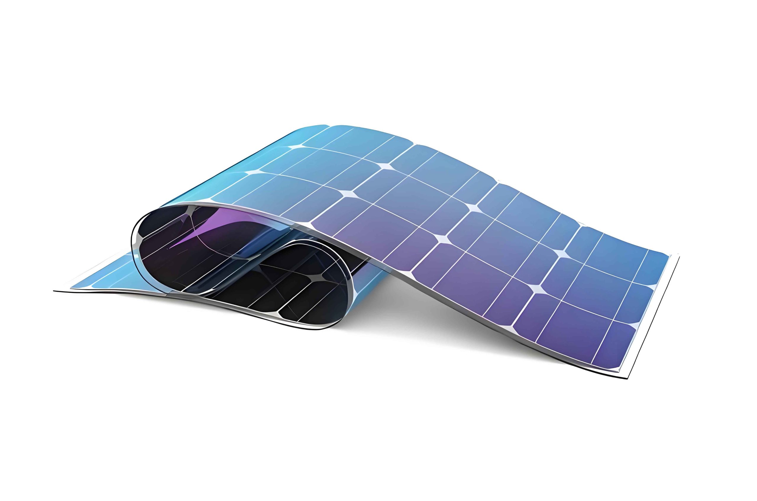
The core challenge we face is that the experimentally achieved PCEs for solution-processed CZTSSe thin film solar panels still lag significantly behind their theoretical potential and behind mature technologies like Cu(In,Ga)Se2 (CIGS). This “efficiency gap” is primarily attributed to high recombination losses stemming from intrinsic point defects (e.g., CuZn antisites, SnZn), band tailing, and the formation of secondary phases or unfavorable interfacial layers like Mo(S,Se)2. Therefore, the choice of solution processing route and its meticulous optimization directly dictates the compositional homogeneity, microstructure, and electronic quality of the final absorber—factors that are paramount for high-performance thin film solar panels.
In this review, we systematically dissect the major solution-based approaches for fabricating CZTSSe absorbers, categorizing them into four distinct families: Spray Pyrolysis, Bath-Based Aqueous Methods, Nanoparticle-Based Inks, and Direct Solution Coating. For each category, we delve into the fundamental principles, analyze key optimization strategies reported in the literature, and summarize the current state-of-the-art performance. We will employ tables to concisely compare results and introduce relevant formulas to elucidate underlying physical principles. Our goal is to provide a clear, comparative analysis that highlights both the unique advantages and persistent challenges of each pathway towards more efficient and commercially viable CZTSSe thin film solar panels.
1. Spray Pyrolysis Deposition
Spray pyrolysis is a versatile and scalable technique where a precursor solution, containing dissolved metal salts and chalcogen sources, is atomized into a fine mist and directed onto a heated substrate. The droplets undergo thermal decomposition upon contact, forming a solid precursor film. A subsequent high-temperature selenization/sulfurization step is usually required to obtain the crystalline kesterite phase suitable for thin film solar panels.
The general reaction during the spray deposition can be conceptualized as the thermal decomposition of metal-thiourea complexes or other precursors. A critical optimization parameter is the [S]/([S]+[Se]) ratio in the final film, which directly controls the bandgap (Eg) of the CZTSSe absorber:
$$E_g(x) = E_{g,CZTSe} + (E_{g,CZTS} – E_{g,CZTSe})x – bx(1-x)$$
where \(x\) is the sulfur fraction [S]/([S]+[Se]), \(E_{g,CZTSe}\) and \(E_{g,CZTSe}\) are the bandgaps of the pure selenide and sulfide endpoints, and \(b\) is the bowing parameter. Optimizing \(x\) is crucial for achieving an ideal bandgap (~1.1-1.2 eV) that maximizes current collection while maintaining a high open-circuit voltage (VOC) in thin film solar panels.
Researchers have explored various solvent systems, including water-alcohol mixtures, dimethylformamide (DMF), and dimethyl sulfoxide (DMSO). The solvent choice affects precursor stability, droplet formation, and the morphology of the as-sprayed layer. For instance, DMF-based solutions have been reported to yield films with superior phase purity and denser morphology compared to aqueous systems. A significant challenge in spray pyrolysis for thin film solar panels is controlling the stoichiometry uniformly across the film and preventing the loss of volatile Sn compounds during the high-temperature processing. Doping strategies, such as incorporating Ag or Mn, have been employed to passivate defects and improve grain growth. The current champion PCE for spray-pyrolyzed CZTSSe thin film solar panels stands at 10.04%, achieved through meticulous optimization of the aqueous precursor and the S/Se ratio.
| Precursor Solvent | Absorber | Key Optimization | PCE (%) | VOC (mV) | JSC (mA/cm²) | FF (%) |
|---|---|---|---|---|---|---|
| Water-Ethanol | CZTSSe | S/Se ratio, annealing | 10.04 | 524 | 30.69 | 62.38 |
| DMF | CZTS | Solvent engineering | 2.04 | 267 | 22.76 | – |
| DMSO | CZTS | Process parameters | 0.46 | 117 | 10.17 | – |
2. Bath-Based Aqueous Solution Methods
This category encompasses electrochemical and electroless deposition techniques performed in aqueous baths. While generally slower than coating methods, they offer excellent uniformity over large areas and high material use efficiency.
2.1 Electrodeposition (ED): This method uses an electrical current to reduce metal ions from an electrolyte onto a conductive substrate (the cathode). It can be performed in either a single-step (co-deposition of all elements) or a sequential (layer-by-layer) manner. The layer-by-layer approach, involving stacks like Cu/Zn/Sn, offers precise control over the initial metal ratios before selenization. The final composition of the absorber in the resulting thin film solar panels is governed by the initial electrodeposited masses and the subsequent reactive annealing. The mass \(m\) of a metal deposited can be estimated by Faraday’s law:
$$m = \frac{QM}{nF}$$
where \(Q\) is the total charge passed, \(M\) is the molar mass, \(n\) is the number of electrons involved in the reduction, and \(F\) is Faraday’s constant. A major challenge is the different electrochemical potentials of Cu, Zn, and Sn, which can lead to non-uniform deposition and adhesion issues. Sequential deposition can cause interfacial voids, while co-deposition may result in dendritic film growth. State-of-the-art electrodeposited CZTSSe thin film solar panels have reached a PCE of 9.9% through optimization of the cation ratio (Cu/(Zn+Sn) ~0.8) and post-deposition treatments to smoothen the film and reduce pinholes.
2.2 Chemical Bath Deposition (CBD) & Successive Ionic Layer Adsorption and Reaction (SILAR): CBD relies on controlled precipitation from a solution onto a submerged substrate. For CZTS, it is typically used to deposit stacked layers of metal sulfides (e.g., ZnS, CuS, SnS). SILAR is a modified, cyclic version where the substrate is alternately immersed in cationic and anionic precursor solutions, with rinsing steps in between, allowing for monolayer-level control. These methods are particularly attractive for their simplicity and low cost. However, they often yield precursor films with fine grains and high porosity, which can lead to poor-quality absorbers after selenization, characterized by small grains and a rough absorber/Mo interface with voids. These morphological defects are detrimental to the performance of the final thin film solar panels, as they increase series resistance and recombination sites. Consequently, the reported efficiencies for pure CBD- or SILAR-fabricated CZTSSe devices remain modest, below 4%.
| Method | Approach | Absorber | PCE (%) | Key Challenge |
|---|---|---|---|---|
| Electrodeposition | Sequential (Cu/Zn/Sn) | CZTSe | 9.10 | Interfacial voids, Sn loss |
| Electrodeposition | Co-deposition | CZTSSe | 9.90 | Dendritic growth, adhesion |
| CBD | Stacked sulfides | CZTSSe | 3.00 | Fine grains, porous morphology |
| SILAR | Cyclic immersion | CZTSSe | 3.74 | Small grain size, high RS |
3. Nanoparticle-Based Ink Methods
In this approach, CZTS or CZTSe nanocrystals (NCs) are first synthesized via colloidal chemistry (e.g., hot-injection, solvothermal methods) and then redispersed in a solvent to form an ink. This ink is coated to form a nanoparticle film, which is then subjected to thermal annealing under Se/S vapor to sinter the nanoparticles into a polycrystalline absorber layer for thin film solar panels.
The hot-injection method is particularly prevalent. It involves rapidly injecting a precursor solution into a hot coordinating solvent (e.g., oleylamine), leading to a burst of nucleation followed by controlled growth. The size and composition of the NCs can be tuned by varying reaction time, temperature, and precursor ratios. The power of this method lies in decoupling the synthesis of the phase-pure kesterite material from the film formation. However, the organic ligands (capping agents) used to stabilize the NCs in solution must be carefully removed during annealing; otherwise, they leave behind a carbon-rich residue that increases series resistance and promotes recombination in the thin film solar panels. Furthermore, the packing density of the NC film is critical—voids between particles can persist after annealing, limiting current collection. Elemental doping at the NC synthesis stage, such as with Ge (to form CZTGSe), has proven effective in improving VOC by reducing band tailing. The highest PCE reported for nanoparticle-based CZTSSe thin film solar panels is 9.4%, achieved using Ge-doped NCs.
4. Direct Solution Coating Methods
This is arguably the most promising and widely researched category for high-efficiency, solution-processed thin film solar panels. It involves dissolving molecular or ionic precursors directly into a solvent to form a homogeneous ink, which is then coated and thermally processed. The solvent system is the defining characteristic.
4.1 Hydrazine-Based Pure Solution: Pioneering work using anhydrous hydrazine (N2H4) as a solvent demonstrated its unparalleled ability to dissolve elemental Cu, Zn, Sn, and S/Se, forming clear, stable precursor solutions. Hydrazine acts as a complexing agent, solvent, and reducing agent. Upon mild heating, it decomposes cleanly, leaving a dense, smooth metallic precursor film ideally suited for conversion into a high-quality absorber. The process benefits from a simple reaction pathway and yields absorbers with large grains and a thin Mo(S,Se)2 interface. This method holds the current efficiency record of 12.6% for all solution-processed CZTSSe thin film solar panels. However, hydrazine is highly toxic, moisture-sensitive, and explosive, posing severe safety and scalability hurdles that preclude its industrial adoption.
4.2 “DMSO-Based” and Related Approaches: The search for benign solvents led to the development of inks based on dimethyl sulfoxide (DMSO) and dimethylformamide (DMF). These solvents dissolve metal salts (e.g., chlorides, acetates) with chalcogen sources like thiourea. A critical breakthrough was establishing a “redox equilibrium” in the precursor solution, preventing the premature precipitation of Cu2S and ensuring homogeneity. The general dissolution reaction for a metal salt Mn+ in a DMSO/thiourea system can be simplified as involving complex formation. Careful control of the annealing profile is essential to drive off solvents and organics while promoting grain growth. DMSO-based processes have yielded champion devices with PCEs exceeding 11%. The addition of small amounts of water or other co-solvents like DMF has been shown to improve ink wettability and film morphology.
4.3 Thiol-Amine Solvent Systems: This highly versatile and lower-toxicity approach uses a mixture of an alkylamine (e.g., ethanolamine, ethylenediamine) and a thiol (e.g., 1,2-ethanedithiol, thioglycolic acid). These solvents can dissolve a wide range of metal oxides, salts, and even elemental powders through complexation. The resulting inks are stable and can be processed in air. A significant advantage is the ability to perform sophisticated doping strategies. For example, a post-deposition treatment involving spin-coating a Na-containing solution onto the CZTS precursor film before selenization has been highly effective. Sodium incorporation facilitates grain growth and increases hole concentration (p), which can be approximated by the defect chemistry involving NaCu acceptors. This approach has recently produced a certified 12.0% (12.3% active area) efficient device, making it the leading non-hydrazine pathway for CZTSSe thin film solar panels.
4.4 Water-Based Approaches: Using water as the primary solvent is the ultimate goal for green, low-cost manufacturing. Recent advances involve using ammonia or amines along with thioglycolic acid to form stable metal-thiolate complexes in aqueous solution. The challenge is to control the drying process to avoid cracks and to manage the strong oxidizing environment during annealing. While promising, the efficiencies of purely water-based processes currently trail behind DMSO and thiol-amine systems.
| Solvent System | Key Features | Champion PCE (%) | Primary Advantages | Primary Challenges |
|---|---|---|---|---|
| Hydrazine (N2H4) | Dissolves elements, clean decomposition | 12.6 | Record efficiency, large grains, simple pathway | Extreme toxicity, explosive, not scalable |
| DMSO/DMF | Dissolves metal salts, non-toxic | 11.2 | Good efficiency, commercially available solvents | Requires redox control, carbon residue management |
| Thiol-Amine (e.g., EDA/EDT) | Dissolves various precursors, tunable | 12.3 | Near-record efficiency, enables easy doping (Na, Ge) | Odor, requires optimized complex chemistry |
| Water/Ammonia-Thiol | Green, low-cost, safe | ~7-8 | Ultimate sustainability, non-flammable | Cracking, oxidation control, lower efficiency so far |
5. Comparative Analysis and Future Perspectives
Having worked with several of these techniques, we can distill their comparative standing in the quest for high-performance CZTSSe thin film solar panels. Spray pyrolysis and bath methods offer good scalability but have historically struggled with fine microstructures and compositional control, limiting their PCE ceiling. Nanoparticle inks provide excellent phase purity from the start but face challenges in removing insulating ligands and achieving dense, void-free sintered films.
Direct solution coating methods, particularly those using DMSO and thiol-amine solvents, have emerged as the most promising. They strike an effective balance between precursor homogeneity, safety, and the ability to form high-quality absorbers with large grains. The recent convergence of efficiencies from these non-hydrazine methods towards the 12% mark is a strong indicator of their potential.
The fundamental efficiency bottleneck for all CZTSSe thin film solar panels, regardless of fabrication method, is the large VOC deficit, defined as:
$$V_{OC-def} = \frac{qE_g}{e} – V_{OC}$$
where \(q\) is the elementary charge, \(E_g\) is the absorber bandgap, \(e\) is Euler’s number (base of natural log), and \(V_{OC}\) is the measured open-circuit voltage. For high-performing CZTSSe devices, this deficit often exceeds 500 mV, compared to ~350 mV for high-efficiency CIGS. This points to persistent bulk and interface recombination.
Therefore, the future research focus must extend beyond simply refining deposition techniques. We believe the next leap in efficiency for solution-processed CZTSSe thin film solar panels will come from a deeper, atomic-level understanding and control of two interconnected domains:
- Precursor Chemistry and Reaction Pathways: Designing molecular precursors and solvent systems that decompose in a more controlled manner, leaving minimal carbon and promoting the direct formation of the kesterite phase with fewer intermediary secondary phases.
- Defect Passivation and Cation Engineering: Systematically exploring isovalent (e.g., Cd, Hg for Zn) and aliovalent (e.g., Ag for Cu, Ge for Sn) substitutions to suppress the formation of detrimental defect clusters like [2CuZn + SnZn] and to reduce band tailing. Alkali metal doping (Na, K, Li) must be optimized not just for grain growth but for specific defect passivation. Innovative post-deposition treatments, similar to those used for CIGS, need to be developed for CZTSSe.
In conclusion, solution processing holds immense promise for the scalable and cost-effective production of kesterite-based thin film solar panels. The performance gap with vacuum methods is closing rapidly. By shifting the research paradigm from simple process optimization to a fundamental focus on controlling the chemical pathway from solution to crystal and the resulting defect landscape, we are confident that solution-processed CZTSSe technology can break the 15% efficiency barrier and solidify its role in the future photovoltaic landscape.