
The global energy landscape is undergoing a significant transformation, driven by the imperative to address climate change and enhance environmental sustainability. Among the various renewable energy sources, solar power, harnessed through photovoltaic technology, has emerged as a pivotal solution. The installation of solar photovoltaic (PV) systems on the rooftops of industrial and commercial buildings has become increasingly prevalent, representing a strategic convergence of energy generation and built infrastructure. This distributed generation model not only contributes to carbon reduction goals but also offers economic benefits through on-site power consumption and potential feed-in to the grid. The core of this model is the solar system, a complex assembly of components working in harmony. The efficiency, reliability, and safety of such a solar system are fundamentally dependent on the quality of its installation and integration. Therefore, a deep understanding of the construction technology, safety protocols, and quality control measures for roof-mounted PV grid-connected projects is paramount for engineers and practitioners. This article delves into the technical intricacies and safety methodologies involved in the installation of these modern energy solar systems.
1. Overview and Operational Principles of Grid-Connected PV Systems
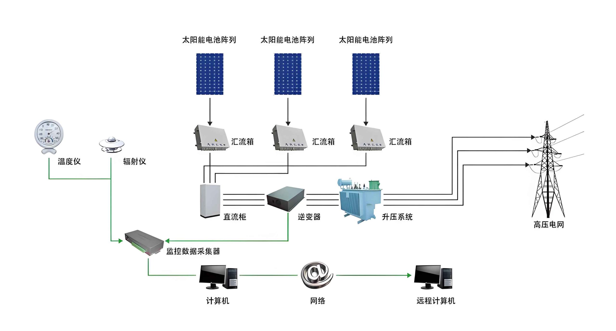
A grid-connected photovoltaic solar system is designed to convert sunlight directly into electricity and synchronize this output with the existing utility grid. Unlike off-grid systems, they do not typically require large-scale battery storage, as the grid acts as a virtual battery, absorbing surplus generation and supplying power when solar production is insufficient. The fundamental operation can be described by the photovoltaic effect, where photons from sunlight strike semiconductor materials within the PV cells, dislodging electrons and creating a flow of direct current (DC) electricity.
The key components of a standard grid-connected solar system include:
1. PV Modules (Panels): Arrays of interconnected solar cells that generate DC power.
2. Mounting Structure: The mechanical framework that securely fixes the panels to the roof at an optimal tilt angle.
3. DC Wiring and Combiner Boxes (String Inverters): Cables that connect modules in series (strings) and parallel, and combiner boxes that consolidate the output of multiple strings.
4. Inverter: The heart of the solar system, which converts the variable DC output from the panels into grid-compliant alternating current (AC).
5. AC Wiring and Protection: Circuit breakers, switches, and cabling to connect the inverter output to the building’s main distribution board or directly to a dedicated grid connection point.
6. Monitoring System: Devices that track the performance and energy yield of the solar system.
The primary operational characteristic is its ability to generate power locally, thereby reducing transmission losses, lowering energy bills, and decreasing the building’s carbon footprint. Any excess energy not consumed on-site is exported to the grid, often under a feed-in tariff or net metering scheme. The entire solar system must adhere to strict grid codes concerning voltage, frequency, synchronization, and safety disconnection (anti-islanding).
2. Technical Workflow and Critical Installation Procedures
The successful deployment of a rooftop PV solar system follows a meticulous sequence of engineering and construction activities. The general workflow can be summarized as: Site Assessment & Design → Preparation & Safety Mobilization → Mechanical Installation (Mounting & Modules) → Electrical Installation (Wiring, Equipment, Grounding) → Commissioning & Grid Integration.
Each phase contains specific technical要点 that demand rigorous attention.
| Phase | Key Activities | Technical Objectives & Formulas |
|---|---|---|
| 1. Preparation & Site Setup | Site clearing, safety barrier setup, material staging, tool and equipment calibration, detailed technical briefing to crew. | Establish a safe working zone. Verify all components against material list and conduct incoming inspection (e.g., module IV curve spot-check). |
| 2. Layout & Marking | Establishing panel array boundaries, locating mounting points, marking rail alignment. | Achieve precise positioning for optimal structural integrity and aesthetic alignment. Use surveying tools (laser levels, theodolites). Accuracy is critical for subsequent steps. |
| 3. Mounting Structure Installation | Installing roof attachments (flashings, anchors), assembling and securing support rails. | Ensure waterproof integrity of roof penetrations. Calculate and verify structural loads. The mounting system must withstand design wind ($F_w$) and snow ($F_s$) loads. $$F_{total} = F_w + F_s$$ Torque values for all fasteners must be per manufacturer’s specification. |
| 4. PV Module Installation | Lifting, positioning, and mechanically/electrically connecting PV modules to the rails. | Avoid micro-cracks (handle with care, use suction lifters). Measure open-circuit voltage ($V_{oc}$) and short-circuit current ($I_{sc}$) of strings before final connection to verify conformity and identify faults. $$P_{max,STC} = V_{mp} \times I_{mp}$$ Ensure proper bonding and grounding of each module frame. |
| 5. Electrical Balance of System (BOS) Installation | Installing DC combiner boxes, cable management (conduits, trays), inverters, AC switchgear, and transformers. | Maintain separation of DC and AC cables. Ensure proper bending radii for cables. Implement comprehensive grounding (< 10 Ω typically). Inverter placement must allow for adequate ventilation. $$I_{cable} \ge 1.25 \times I_{sc,string} \times 1.25$$ (Derating factors for temperature and conduit fill apply). |
| 6. Commissioning & Grid Connection | Pre-energization checks, insulation resistance tests, functional tests of protection devices, inverter start-up, synchronization with grid. | Verify all electrical parameters (voltage, frequency, phase sequence) match grid requirements. Anti-islanding protection must be tested and validated. Performance ratio (PR) is a key initial metric: $$PR = \frac{Y_f}{Y_r} = \frac{\text{Actual Yield}}{\text{Theoretical Yield (at STC)}}$$ |
2.1 Electrical Installation: Detailed Protocols
The electrical installation is the nervous system of the PV solar system, requiring precision to ensure safety, performance, and longevity.
Combiner Box Installation: Combiner boxes, which consolidate multiple PV strings, must be installed securely and protected from environmental stress. They should be mounted in locations that minimize cable run lengths and allow for easy maintenance. Internal string fusing and surge protection devices (SPDs) are critical for safety. All connections must be torqued to specification to prevent hot spots due to loose terminals, which can be modeled by Joule’s law:
$$P_{loss} = I^2 \times R_{contact}$$
where a high contact resistance ($R_{contact}$) leads to significant power loss and heat generation.
Cable Tray (Bridge) and Conduit Installation: Cable management systems must be designed to support the weight of cables, provide protection from physical damage, and allow for heat dissipation. Supports should be spaced according to the tray manufacturer’s guidelines and the weight of the cables. The fill ratio of conduits should not exceed recommended limits (often 40% for three or more cables) to prevent overheating. The cross-sectional area of the cable must be calculated based on the maximum current and allowable voltage drop, typically limited to 1-3% for DC sides:
$$\Delta V = 2 \times L \times I \times R / 1000$$
(For DC circuits, where L is one-way length in meters, I is current in Amps, R is resistance per km).
Inverter and Switchgear Installation: The inverter is the most sensitive electronic component. It requires a clean, dry, cool, and well-ventilated environment. The foundation or wall-mounting must be vibration-free. Input DC and output AC connections must be unequivocally correct. The grid-side AC protection (circuit breakers, contactors) must be correctly rated for the inverter’s maximum output current and feature appropriate short-circuit and overload protection. The coordination between these protective devices and the inverter’s internal protections is essential for selective tripping.
2.2 Grounding and Bonding
A robust grounding (earthing) system is non-negotiable for safety and system performance. It serves two main purposes: Equipment Grounding (safety grounding) to protect personnel from electric shock by providing a low-impedance path for fault current, and System Grounding for voltage stabilization and surge protection. All non-current-carrying metal parts—module frames, mounting rails, combiner boxes, inverter enclosures—must be bonded together and connected to the building’s grounding electrode system. The grounding resistance should be measured and verified to be below the project specification (often less than 10 ohms). The use of dedicated grounding lugs and corrosion-resistant connectors is mandatory.
3. Quality Control and Assurance Framework
Quality must be engineered into every phase of the solar system installation. A proactive Quality Control (QC) and Quality Assurance (QA) plan is essential.
Inspection and Test Points (ITPs): A series of predefined checks must be conducted and documented.
| Stage | Quality Checkpoint | Acceptance Criteria |
|---|---|---|
| Material Receiving | Visual inspection of modules, rails, inverters for damage. Check certifications (UL, IEC). | No physical damage. Model numbers match datasheet. Packaging intact. |
| Post-Structure Install | Torque audit of roof attachments and rail connections. Waterproofing integrity check. | All fasteners torqued to spec. No signs of roof membrane compromise. |
| Post-Module Install | Visual inspection for cracks, alignment. Measurement of string $V_{oc}$ & $I_{sc}$. | No cell cracks. String voltages within calculated range (considering temperature). |
| Pre-Commissioning | Continuity and insulation resistance (IR) tests. Ground resistance measurement. | IR > 1 MΩ for DC circuits (per IEEE 624). Ground resistance < specified value. |
| Commissioning | Functional tests of all isolators, breakers, inverters. Verification of grid synchronization. | All functions operate as designed. Inverter connects to grid smoothly and produces power. |
Process Control: Adherence to documented procedures (Standard Operating Procedures – SOPs) for critical tasks like lifting, electrical terminations, and torque application is mandatory. Regular audits ensure compliance. Non-conformances identified during inspections must be tracked, addressed, and closed out through a formal corrective action process. This systematic approach ensures the long-term reliability and performance of the entire solar system.
4. Safety and Environmental Management Protocols
Roof-top construction presents unique hazards. A comprehensive Job Safety Analysis (JSA) must precede work.
Fall Protection: This is the highest priority. Guardrails, safety nets, or personal fall arrest systems (PFAS) must be used when working near roof edges or on sloped surfaces. All workers must be trained in their use.
Electrical Safety: Working on live circuits should be avoided. A strict Lock-Out/Tag-Out (LOTO) procedure must be enforced for all electrical work during installation and maintenance. Before working on any DC circuit, even disconnected, capacitors within inverters or optimizers must be allowed to discharge. Use insulated tools and wear appropriate personal protective equipment (PPE) including voltage-rated gloves and glasses.
Material Handling: PV modules are heavy, fragile, and slippery. Proper lifting techniques and equipment (like vacuum lifters) must be employed to prevent musculoskeletal injuries and module damage. Staging areas must be organized to prevent tripping hazards.
Weather Awareness: Work must be suspended during high winds, rain, or lightning storms due to risks of falls, electric shock, and module damage.
Environmental Protection: The installation process must minimize waste. Packaging materials (cardboard, plastics) should be collected for recycling. Drilling debris and cable cuttings must be properly disposed of. The design of the solar system itself inherently contributes to environmental protection by offsetting fossil fuel generation. The lifecycle carbon savings of a solar system can be approximated as:
$$CO2_{saved} = E_{annual} \times EF_{grid} \times Lifetime$$
where $E_{annual}$ is annual energy production, and $EF_{grid}$ is the grid emission factor.
| Hazard Category | Specific Risk | Mitigation Measure |
|---|---|---|
| Fall from Height | Working on roof edge, slippery surface. | PFAS with anchor points, guardrails, non-slip footwear. |
| Electric Shock | DC arc flash (high voltage strings), AC connection. | LOTO, insulated tools, DC string fusing, “test before touch”. |
| Musculoskeletal | Lifting heavy modules, awkward postures. | Use mechanical aids (lifters), team lifting, proper ergonomics. |
| Weather | Lightning strike, high wind, extreme heat. | Monitor forecasts, suspend work, provide hydration and shade. |
In conclusion, the installation of a roof-mounted grid-connected photovoltaic solar system is a multidisciplinary engineering endeavor that extends far beyond simply mounting panels on a roof. It encompasses precise mechanical engineering, meticulous electrical integration, rigorous quality assurance, and uncompromising safety management. Each installed solar system represents a long-term investment in clean energy infrastructure. Its performance, safety, and return on investment are directly tied to the technical competence and procedural discipline applied during its construction. By adhering to the detailed technical workflows, implementing robust quality controls, and prioritizing comprehensive safety and environmental measures, installers can ensure that these solar systems operate reliably, safely, and at peak efficiency for their entire service life, thereby maximizing their contribution to a sustainable energy future.