
The pursuit of advanced materials for energy storage and high-temperature industrial applications drives continuous innovation. This article delves into two significant technological domains: the production of ultra-large graphite electrodes through optimized Acheson graphitization processes and the development of next-generation solid-state batteries with exceptional charging rates. From the fundamental principles governing thermal gradients in massive carbon bodies to the intricate challenges of solid-solid interfaces in electrochemical cells, we explore the scientific and engineering advancements that enable these breakthroughs. We will employ detailed tables to summarize critical parameters and utilize mathematical formulations to describe underlying physical phenomena, providing a comprehensive technical overview.
Part I: Advanced Graphitization for Large-Scale Electrode Production
The manufacturing of graphite electrodes for electric arc furnaces, particularly those with diameters exceeding one meter, presents formidable challenges. The core process, graphitization, involves heating carbonaceous bodies to temperatures above 2500°C to transform amorphous carbon into a crystalline graphite structure. For large-diameter electrodes, the internal thermal stresses generated during rapid heating can lead to catastrophic cracking. The Acheson furnace process, where the electrode itself acts as the heating element (direct resistance heating), is particularly sensitive to these effects due to the significant temperature gradient between the hot core and the cooler surface.
The central problem revolves around managing the joule heating and consequent thermal expansion. The heat generation per unit volume, $q”'(x,t)$, is governed by the local electrical resistivity $\rho_e(T)$ and the current density $J$:
$$ q”'(x,t) = J^2 \cdot \rho_e(T(x,t)) $$
Where $T(x,t)$ is the temperature field, which is a function of both radial position $x$ and time $t$. The resulting non-uniform thermal expansion induces mechanical stress. The radial stress $\sigma_{rr}$ can be approximated for a long cylinder under a parabolic temperature distribution $T(r) = T_c – (T_c – T_s)(r/R)^2$ as:
$$ \sigma_{rr}(r) \approx \frac{\alpha E}{1-\nu} \left[ \frac{1}{R^2} \int_0^R T(r’) r’ dr’ – \frac{1}{r^2} \int_0^r T(r’) r’ dr’ \right] $$
Here, $\alpha$ is the coefficient of thermal expansion (CTE), $E$ is Young’s modulus, $\nu$ is Poisson’s ratio, $T_c$ is the center temperature, $T_s$ is the surface temperature, and $R$ is the electrode radius. For a 1080 mm diameter electrode, the radial CTE mismatch is more severe than the axial one, making radial stress management paramount. This necessitates a meticulously controlled power profile during the graphitization cycle to minimize the gradient $(T_c – T_s)$.
The successful production of such large electrodes required a holistic re-engineering of the graphitization furnace system. Modifications included widening the furnace chamber to accommodate the larger loads, redesigning the furnace head electrodes and associated copper busbars with enhanced cooling systems to handle the extreme currents, and refining the packing material (coke bed) to ensure uniform thermal insulation and current distribution. The cornerstone of the process, however, is the precisely calculated power schedule, tailored to the specific electrical parameters of the rectifier system.
The power curve was designed to ramp gradually, controlling the rate of temperature rise to mitigate thermal shock. The key electrical and process parameters for the 1080 mm electrode graphitization run are summarized below:
| Parameter | Start of Cycle | Peak/Mid-Cycle | End of Cycle |
|---|---|---|---|
| Furnace Power (kW) | 2,700 | 15,800 (Max) | Ramped Down |
| Power Stability (±) | ±50 kW (below 5 MW) | ±200 kW (above 5 MW) | — |
| Furnace Resistance (Ω) | 2.804 | — | 0.828 |
| Rectifier Current (kA) | 31.8 | — | 133.92 |
| Current Density in Electrode (A/cm²) | — | 14.6 (Maximum) | — |
| Total Cycle Time (hours) | 32 | ||
| Maximum Allowable Cool-down Temperature | 400 °C (to prevent oxidation) | ||
The process culminated in the successful production of electrodes. The quality was verified by measuring the electrical resistivity, a key performance indicator. The results, taken from multiple points on east and west side samples, confirmed compliance with the industry standard (YB/T4300-2012), which requires a resistivity $\leq 18 \mu\Omega \cdot m$.
| Sample Location (East) | Resistivity ($\mu\Omega \cdot m$) | Sample Location (West) | Resistivity ($\mu\Omega \cdot m$) |
|---|---|---|---|
| E1 | 11.5 | W1 | 11.3 |
| E2 | 11.6 | W2 | 10.8 |
| E3 | 11.0 | W3 | 11.2 |
| E4 | 10.8 | W4 | 10.8 |
| E5 | 10.7 | W5 | 10.9 |
| E6 | 10.9 | W6 | 10.5 |
| E7 | 10.6 | W7 | 10.2 |
| E8 | 11.1 | W8 | 10.9 |
| E9 | 11.3 | W9 | 11.2 |
| E10 | 11.4 | W10 | 11.5 |
This achievement demonstrates that through systematic furnace modification and a physics-based optimization of the electrical heating profile, the limits of conventional graphitization technology can be extended. The knowledge gained is directly transferable to other configurations, such as multi-stack loading for smaller electrodes or the graphitization of cathode blocks, enhancing overall production flexibility and capability.
Part II: The Paradigm Shift to Solid-State Batteries
Concurrently, a revolution is underway in electrochemical energy storage. The limitations of conventional lithium-ion batteries, which employ liquid organic electrolytes—namely, flammability, leakage, limited temperature operating window, and dendrite formation—have spurred intensive global research into solid-state batteries. A solid-state battery replaces the liquid electrolyte and separator with a solid ion-conducting material. This fundamental change promises immense benefits: superior safety (no fire or explosion risk from liquid leakage), potential for higher energy density (enabling lithium metal anodes), wider operational temperature ranges, and longer cycle life.
The core principle remains the same: Li-ions shuttle between anode and cathode during discharge and charge. However, the transport mechanism changes. In a liquid electrolyte, ion mobility $\mu_{ion}$ is high, and the electrolyte permeates the porous electrode, creating a vast, intimate liquid-solid contact area $A_{contact}$. The effective ionic conductivity $\sigma_{eff}$ within the composite electrode is described by percolation theory and microstructural parameters like porosity $\epsilon$ and tortuosity $\tau$:
$$ \sigma_{eff} = \sigma_{bulk} \cdot \frac{\epsilon}{\tau} $$
In a solid-state battery, the solid electrolyte must maintain perfect contact with solid electrode particles. The interface is rigid, and any micro-scale separation or interfacial reaction creates a high impedance. The total cell resistance $R_{cell}$ becomes dominated by interfacial resistances $R_{int,anode}$ and $R_{int,cathode}$ in addition to the bulk resistances of the layers:
$$ R_{cell} = R_{bulk,anode} + R_{int,anode} + R_{bulk,electrolyte} + R_{int,cathode} + R_{bulk,cathode} $$
Minimizing $R_{int}$ is the single greatest challenge in realizing a high-power solid-state battery.
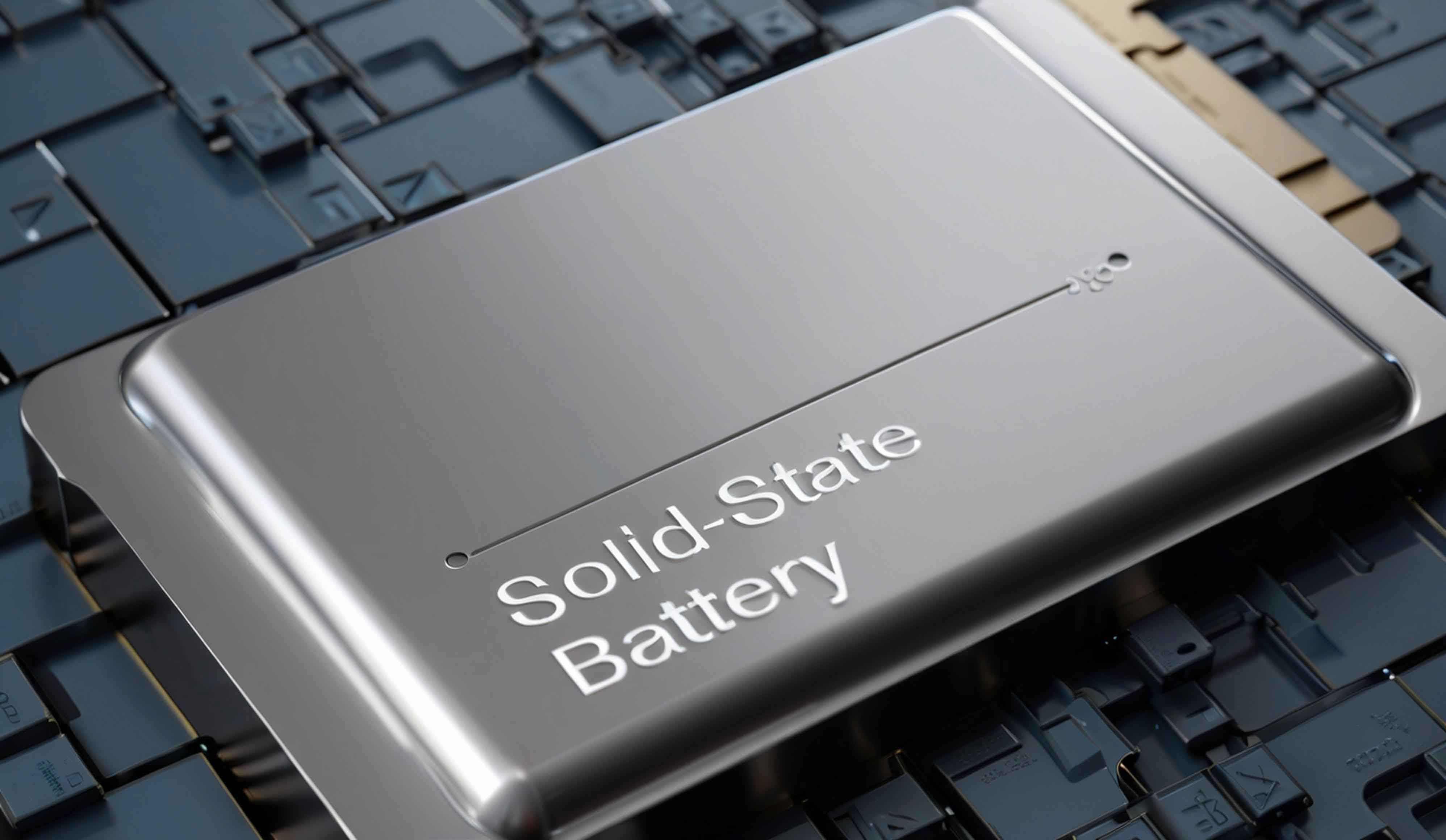
Historically, the low current throughput of solid-state batteries has resulted in impractically long charge times, often cited in the range of 10-12 hours for a full charge. This is primarily due to the high interfacial resistance mentioned above. A breakthrough in this area has been achieved through a novel cell design focusing on material compatibility. The innovation lies in fabricating both the cathode composite and the solid electrolyte separator from chemically similar phosphate-based compounds. This similarity in composition and crystal structure reduces interfacial lattice mismatch and minimizes the formation of high-resistance interphases.
The fabrication process is ingenious. A dense, stable phosphate solid electrolyte layer acts as the mechanical substrate. Electrode layers are then applied on both sides using a scalable screen-printing technique, employing phosphate-based active materials and ionic conductors. This creates a monolithic, chemically coherent cell stack. The intimate contact achieved through this compatible materials approach drastically lowers the interfacial charge transfer resistance, enabling unprecedented current density.
The performance metrics of this novel solid-state battery design are transformative, particularly in terms of rate capability. While maintaining the inherent safety of a solid-state battery, it achieves a charging time of under one hour, an order-of-magnitude improvement over previous solid-state designs. The following table compares key characteristics of this new battery with conventional lithium-ion and earlier solid-state concepts.
| Battery Characteristic | Conventional Liquid Li-ion | Typical Solid-State Battery (Previous) | Novel Phosphate-Based Solid-State Battery |
|---|---|---|---|
| Electrolyte State | Liquid Organic Solvent + Salt | Solid (e.g., Sulfide, Oxide) | Solid Phosphate |
| Key Safety Concern | Flammability, Leakage | Very Low (Intrinsically Safe) | Very Low (Intrinsically Safe) |
| Max. Charging Rate (C-rate) | 1C-3C (Fast-Charging Types) | ~0.1C | >1C |
| Typical Full Charge Time | 1-3 hours | 10-12 hours | < 1 hour |
| Cycle Life (Capacity Retention) | 80% after 500-1000 cycles | Varies, often limited by interface | 84% after 500 cycles |
| Energy Density (Gravimetric) | ~150-250 Wh/kg | High Potential (~300+ Wh/kg) | ~120 mAh/g (Active Material) |
| Interfacial Engineering | SEI Layer (Stable) | Major Challenge (High $R_{int}$) | Material Compatibility (Low $R_{int}$) |
The electrochemical performance can be modeled. The cell’s ability to deliver high current is reflected in its area-specific impedance (ASI). For a solid-state battery with good interfacial design, the Butler-Volmer equation for the interfacial current density $j$ simplifies as the charge transfer resistance $R_{ct}$ is lowered:
$$ j = j_0 \left[ \exp\left(\frac{\alpha n F \eta}{RT}\right) – \exp\left(-\frac{(1-\alpha) n F \eta}{RT}\right) \right] $$
Where $j_0$ is the exchange current density (high for good interfaces), $\alpha$ is the charge transfer coefficient, $n$ is the number of electrons, $F$ is Faraday’s constant, $\eta$ is the overpotential, $R$ is the gas constant, and $T$ is temperature. A high $j_0$ allows for large $j$ (fast charging) at a moderate $\eta$, preventing lithium plating. The achieved capacity of 120 mAh per gram of active material is commendable, though there is a recognized pathway to further increase energy density by optimizing the electrode formulation and thickness.
The implications of this development are profound. The combination of safety, rapid charging, and decent cycle life opens up applications far beyond consumer electronics. Electric vehicles stand to benefit enormously from a solid-state battery that charges as quickly as refueling a gasoline car while eliminating fire risk. The aerospace industry requires ultra-safe, reliable batteries for aircraft and satellites. Smart grid storage and medical implants also demand the longevity and safety profile intrinsic to a well-designed solid-state battery.
Part III: Synthesis and Future Trajectories
Both technological narratives—mastering macro-scale thermal-electrical-mechanical coupling in graphite production and conquering micro-scale ionic transport at solid-solid interfaces in electrochemistry—share a common theme: the triumph of materials science and precision engineering over intrinsic physical limitations. The graphitization work translates fundamental understanding of thermal stress into a practical, controlled power curve, enabling larger, more efficient industrial components. The solid-state battery breakthrough hinges on the conceptual leap of using chemically homologous materials to create a seamlessly integrated, low-impedance electrochemical cell.
Looking forward, the trajectory for large electrode manufacturing involves further digitalization, using real-time furnace resistance and temperature modeling to dynamically adjust the power profile for even larger diameters or different material grades, minimizing energy consumption and maximizing yield. For the solid-state battery, the path is clear: scale-up of the novel phosphate-based manufacturing process, enhancement of the energy density to surpass incumbent lithium-ion technology, and rigorous testing under real-world automotive and aerospace conditions. The ultimate goal is a commercial solid-state battery that is safer, charges faster, and lasts longer than anything available today.
The mathematical frameworks governing these processes will continue to be refined. For graphitization, coupled electro-thermal-stress finite element models will become standard for process design. For solid-state batteries, models integrating interfacial ion transport, mechanical stress evolution during cycling, and dendrite nucleation criteria in solid electrolytes are active areas of research. The continuous interplay between theoretical modeling and empirical innovation, as demonstrated in both fields discussed here, remains the engine of technological progress.
In conclusion, the advancement of graphite electrode production and the emergence of high-performance solid-state batteries exemplify the depth of modern materials engineering. From the extreme environment of a 3000°C graphitization furnace to the nanoscale interface within a battery cell, solving these challenges requires a holistic approach. It is through such dedicated research and development that foundational industrial processes are optimized and transformative energy storage technologies, particularly the promising solid-state battery, are brought from the laboratory to the marketplace, powering a more efficient and sustainable future.