
As a researcher focused on electrochemical energy storage safety, I have observed the rapid proliferation of lithium iron phosphate (LiFePO4 or lifepo4) batteries across electric mobility and grid-scale storage applications. Often hailed as the “safety guardian” within the lithium-ion family, the lifepo4 battery has earned its reputation through superior thermal stability and tolerance to electrical abuse compared to other chemistries. However, my analysis of recent high-profile fire incidents reveals that this inherent safety is not absolute. These events underscore significant hidden hazards under extreme conditions, demanding a deeper, multidimensional understanding. In this article, I will systematically dissect the root causes, evolution patterns, and unique challenges associated with lifepo4 battery fires. Moving beyond the limitations of conventional firefighting, I will explore innovative mitigation technologies and holistic safety strategies, aiming to provide scientific guidance for enhancing the intrinsic safety and sustainable deployment of lifepo4 battery systems.
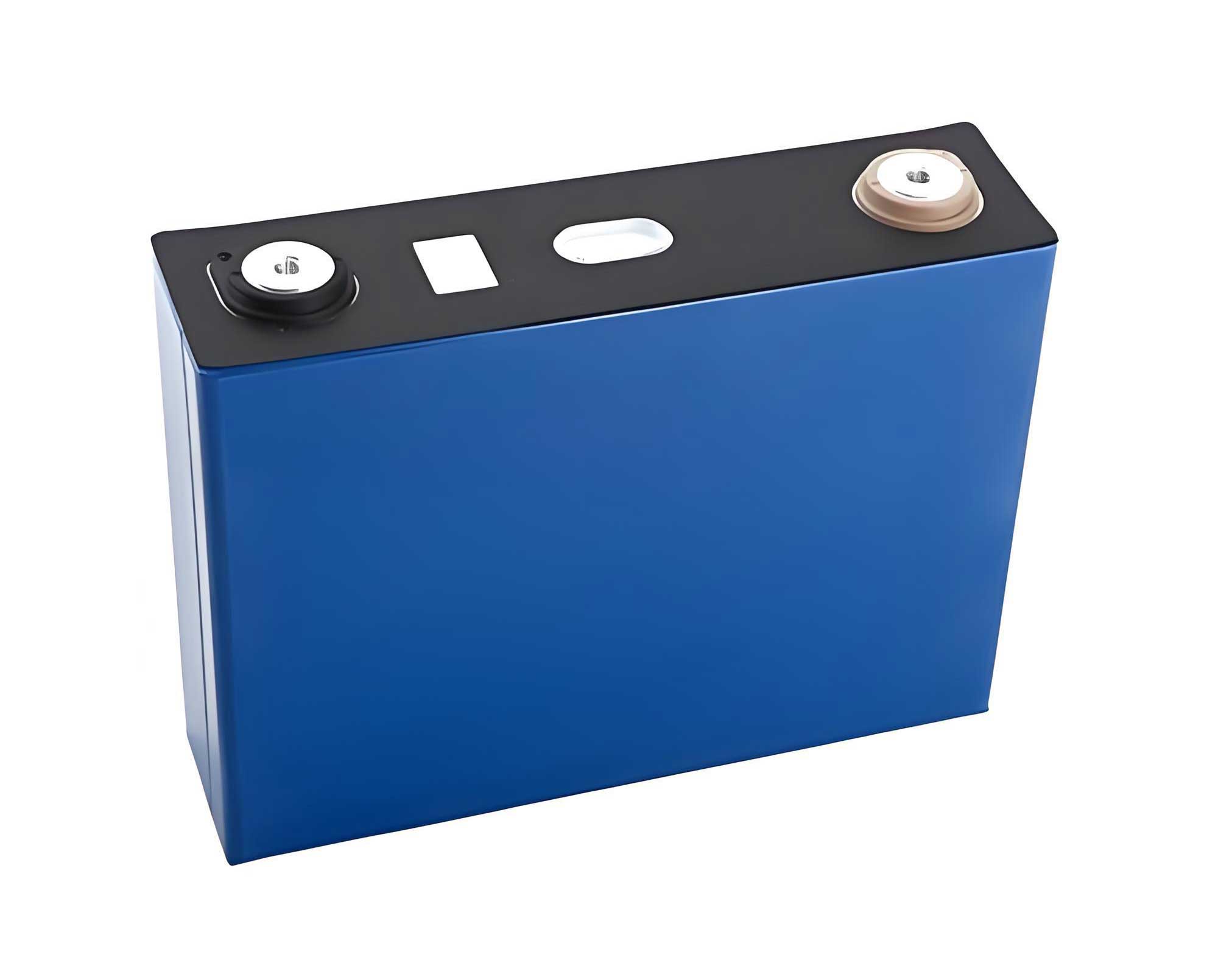
Fundamental Principles and Intrinsic Safety of the Lifepo4 Battery
To comprehend its failure modes, one must first understand the foundational architecture of the lifepo4 battery. At its core, a single cell consists of a lithium iron phosphate (LiFePO4) cathode, a graphite-based anode, a separator (typically polyolefin), and an electrolyte composed of lithium salts (e.g., LiPF6) dissolved in organic carbonate solvents. The defining feature lies in the olivine crystal structure of the cathode material. This structure, with strong P-O covalent bonds, provides exceptional stability, limiting oxygen release even at elevated temperatures. The operation relies on the reversible shuttling of lithium ions (Li+) between the cathode and anode during charge and discharge, a process governed by electrochemical potentials.
The safety pedigree of the lifepo4 battery is primarily attributed to this robust cathode. Unlike layered oxide cathodes (e.g., NMC, NCA, LCO), the olivine structure of LiFePO4 remains remarkably stable. Its thermal decomposition temperature is significantly higher, and it does not undergo exothermic phase changes that release large amounts of oxygen, which is a primary fuel source in other lithium-ion battery fires. This intrinsic stability is the cornerstone of the lifepo4 battery’s safety advantage.
The following table contrasts key safety-related properties of common lithium-ion battery chemistries:
| Battery Chemistry | Cathode Material | Typical Thermal Runaway Onset Temp. | Oxygen Release upon Heating | Relative Energy Density | Inherent Safety Profile |
|---|---|---|---|---|---|
| Lifepo4 (LFP) | LiFePO4 | ~200-250°C | Negligible | Medium | Excellent |
| Lithium Cobalt Oxide (LCO) | LiCoO2 | ~150-180°C | Significant | High | Poor |
| Nickel Manganese Cobalt (NMC) | LiNixMnyCozO2 | ~180-220°C | Significant | Very High | Medium |
| Lithium Manganese Oxide (LMO) | LiMn2O4 | ~200-250°C | Moderate | Medium | Good |
The nominal voltage of a single lifepo4 battery cell is approximately 3.2 V, and its specific energy can be described by:
$$E_{specific} = \frac{nFV}{M}$$
where \( n \) is the number of electrons transferred per formula unit (1 for LiFePO4), \( F \) is Faraday’s constant, \( V \) is the average cell voltage, and \( M \) is the molar mass of the active materials. While this results in a lower gravimetric energy density compared to NMC or NCA, the stability trade-off is crucial for safety-critical applications.
Deconstructing the Thermal Runaway Mechanism in Lifepo4 Batteries
Despite its robust cathode, a lifepo4 battery is not immune to failure. Thermal runaway (TR) is a chain of exothermic reactions leading to uncontrollable self-heating. I have identified that the primary triggers for a lifepo4 battery include:
- Electrical Abuse: Overcharge, over-discharge, or external/internal short circuits.
- Thermal Abuse: External heating or inadequate cooling.
- Mechanical Abuse: Crush, penetration, or severe vibration.
The TR sequence in a lifepo4 battery, while less violent than in other types, follows a critical path:
- Initial Heating & SEI Decomposition: As temperature rises (~80-120°C), the Solid Electrolyte Interphase (SEI) on the graphite anode begins to decompose exothermically.
- Anode-Electrolyte Reaction: With the SEI compromised, the exposed anode reacts directly with the electrolyte, generating more heat and flammable gases (e.g., H2, CO, CH4).
- Separator Meltdown: Around 130-150°C, the polyolefin separator melts, causing a massive internal short circuit and a sharp temperature spike.
- Electrolyte Decomposition & Combustion: The organic carbonate solvents in the electrolyte vaporize and decompose, producing more combustible gas. Upon contacting high-temperature components or igniting, these gases fuel a flaming fire.
- Cathode & Binder Reactions: At very high temperatures (>250°C), the LiFePO4 cathode may undergo limited decomposition, and the polyvinylidene fluoride (PVDF) binder can react exothermically.
The total heat generation rate (\( Q_{gen} \)) during TR can be modeled as the sum of individual reaction heats:
$$Q_{gen} = I^2 R + \sum \Delta H_i \frac{d\xi_i}{dt}$$
where \( I^2 R \) is Joule heating from internal short circuits, \( \Delta H_i \) is the enthalpy of reaction \( i \), and \( \frac{d\xi_i}{dt} \) is its rate. The key for the lifepo4 battery is that the sum of \( \Delta H_i \) for cathode-related reactions is significantly lower than for NMC or LCO.
The following table summarizes the key exothermic reactions and their approximate temperature ranges in a failing lifepo4 battery:
| Stage | Primary Reaction | Approx. Temp. Range | Key Hazard Output |
|---|---|---|---|
| 1. SEI Breakdown | SEI (Li2CO3, ROLi, etc.) → LiF + gases | 80 – 120 °C | Heat, minor gases |
| 2. Anode Reaction | Graphite (LixC6) + Electrolyte → LiF + C + gases (H2, C2H4, etc.) | 120 – 200 °C | Substantial heat, flammable gases |
| 3. Separator Collapse | PE/PP Melting | 130 – 150 °C | Internal short, rapid heating |
| 4. Electrolyte Decomposition | EC, DEC, EMC → CO2, CO, CxHy, etc. | > 150 °C | Vapors, flammable gases, heat |
| 5. Cathode Decomposition* | 2LiFePO4 → Fe2P2O7 + Li3PO4 + … | > 250 °C | Limited heat, no free O2 |
| 6. PVDF Binder Reaction* | PVDF + LixC6 / O2 → HF + heat | > 300 °C | Toxic HF gas, heat |
*Reactions 5 & 6 are minor or occur very late compared to other Li-ion chemistries.
Unique Fire Behavior and Hazards of a Lifepo4 Battery Pack
When thermal runaway propagates within a module or pack, the resulting fire exhibits distinct and challenging characteristics that I have categorized as follows:
1. High-Temperature, Sustained Burning: While the lifepo4 battery cathode itself is stable, the combustible electrolyte and other components (binders, plastics) provide ample fuel. Pack fires can sustain temperatures between 800°C and 1000°C. This intense heat can cause thermal runaway propagation to adjacent cells via conduction, convection, and radiation. The heat flux (\( \dot{q}” \)) driving propagation can be estimated for conductive paths:
$$\dot{q}” = -k \frac{\Delta T}{\Delta x}$$
where \( k \) is the thermal conductivity of cell casing or busbars, \( \Delta T \) is the temperature difference between a failing and a neighboring cell, and \( \Delta x \) is the separation distance.
2. Pronounced Re-ignition Tendency: This is a hallmark challenge. Even after visible flames are extinguished, residual heat within the densely packed cells can keep internal temperatures above the ignition point of released gases or cause renewed internal shorting. This leads to frequent and unpredictable re-ignition events, sometimes hours or days later.
3. Toxic and Corrosive Gas Emission: The most severe toxicological hazard comes from the generation of Hydrogen Fluoride (HF). This occurs primarily from the thermal decomposition of the LiPF6 salt and the reaction of the PVDF binder:
$$\text{LiPF}_6 \xrightarrow{\Delta} \text{LiF} + \text{PF}_5$$
$$\text{PF}_5 + \text{H}_2\text{O} \rightarrow 2\text{HF} + \text{POF}_3$$
$$\text{PVDF} + \text{Heat/O}_2 \rightarrow \text{HF} + \text{Carbonaceous compounds}$$
HF is highly toxic, corrosive, and forms opaque white fumes, severely complicating rescue efforts. Other gases include CO, CO2, and various hydrocarbons.
4. Difficult Fire Suppression: The compact, often sealed design of a lifepo4 battery pack hinders the penetration of extinguishing agents to the seat of the fire. Furthermore, the ongoing electrochemical and chemical reactions can generate their own oxidants, rendering oxygen-depletion tactics less effective.
The table below synthesizes the key fire characteristics and their implications:
| Fire Characteristic | Description | Primary Hazard & Challenge |
|---|---|---|
| High Core Temperature | Sustained 800-1000°C in pack fire. | Structural damage, rapid thermal propagation, difficult cooling. |
| Jet Flames & Projectiles | Vented gases igniting from cell safety vents. | Direct flame impingement, ignition of nearby fuels. |
| Re-ignition (Recurrence) | Multiple flare-ups after initial suppression. | Prolonged incident, safety risk for responders, resource drain. |
| Toxic Gas Cloud (HF, CO) | Generation of corrosive and poisonous fumes. | Life safety for occupants/responders, environmental contamination. |
| Electrical Hazard | High voltage remains present in undamaged sections. | Risk of electric shock to responders during suppression. |
Inadequacy of Conventional Firefighting Methods for Lifepo4 Battery Fires
Standard fire suppression techniques often prove inadequate or even counterproductive when confronting a lifepo4 battery fire. My evaluation of common agents is as follows:
Water: While water has excellent cooling capacity, its application is problematic. Large volumes are needed, leading to runoff contaminated with toxic fluorides and lithium. Water can also conduct electricity, posing a shock hazard if the pack’s high-voltage system is not fully isolated. Crucially, water cannot easily penetrate the cell casing to cool the internal jelly roll where reactions persist.
Dry Chemical Powder (ABC): These powders (e.g., monoammonium phosphate) work by interrupting the chemical chain reaction at the flame surface. They are ineffective at cooling the battery’s internal mass. The powder forms a crusty residue that insulates the cells, trapping heat and potentially exacerbating re-ignition. Cleanup is also extremely difficult and can damage sensitive electronics.
Carbon Dioxide (CO2): CO2 acts by oxygen dilution and cooling. Its effect is temporary in an open or ventilated space. Since a decomposing lifepo4 battery can produce its own oxidants, the fire can readily re-establish once the CO2 dissipates. It offers no cooling to the battery core.
Standard Foams (AFFF/AR-AFFF): Designed for liquid fuel fires, foams provide a sealing blanket. They are not formulated to handle the complex, deep-seated, and electrically-live nature of a lifepo4 battery fire. They offer minimal cooling penetration and can be electrically conductive when aspirated.
An Integrated Strategy for Prevention, Control, and Emergency Response
Mitigating the risk of a lifepo4 battery fire requires a multi-layered defense-in-depth approach spanning design, monitoring, suppression, and emergency procedures. I propose the following integrated strategy:
1. Advanced Battery Management & Thermal Control
The first line of defense is preventing the conditions that lead to thermal runaway.
- Enhanced BMS Algorithms: The Battery Management System (BMS) must go beyond voltage and current limits. It should incorporate sophisticated state estimation (SOC, SOH, SOE) and, crucially, State of Safety (SOS) algorithms. These can use models to predict internal short circuits based on subtle voltage divergence, self-discharge rates, or impedance spectroscopy data.
- Multi-Modal Thermal Management: A robust system is non-negotiable. For large-scale lifepo4 battery energy storage systems (BESS), liquid cooling with direct contact to cell walls is highly effective. The cooling power must be dynamically controlled. The required cooling capacity (\( P_{cool} \)) to counteract heat generation can be expressed as:
$$P_{cool} = \dot{m} c_p \Delta T + Q_{loss}$$
where \( \dot{m} \) is the coolant mass flow rate, \( c_p \) is its specific heat capacity, \( \Delta T \) is its temperature rise, and \( Q_{loss} \) represents heat loss to surroundings.
Phase Change Materials (PCMs) integrated into the module can absorb peak heat loads during early-stage TR, delaying propagation.
2. Innovative Fire Suppression and Containment Agents
When prevention fails, the suppression system must be tailored to the chemistry.
- Water Mist with Additives: Fine water mist (< 400 µm droplets) provides efficient cooling with less water. Additives like fluorinated surfactants can improve wetting and penetration. More importantly, aqueous vermiculite dispersions or similar agents can be used. The water provides cooling, while the vermiculite forms an insulating, oxygen-barrier cake over the cells.
- Specialized Aerosols & Gaseous Agents: Condensed aerosol generators release fine solid particulates (K2CO3, etc.) that inhibit combustion reactions. They can permeate enclosures more effectively than powders. Inert gases like NOVEC™ 1230 are effective in flooding sealed compartments, providing cooling and oxygen displacement without residue.
- Direct Cell-to-Cell Propagation Barriers: Implementing intumescent materials between cells is critical. These materials expand dramatically when heated (e.g., at 150-200°C), forming a thick, insulating char that blocks heat transfer and physically separates failing cells, effectively slowing or stopping the domino effect within a lifepo4 battery module.
3. System-Level Design and Compartmentalization
Architectural design limits the scale of any incident.
- Fire-Resistant Enclosures: Packs and modules should be housed in enclosures rated to withstand high temperatures for a specified duration (e.g., 1-hour fire rating).
- Venting and Gas Management: Designated, directed venting channels must safely route hot, toxic gases from a failing cell away from other cells and out of the enclosure to a safe location, preventing overpressure and internal gas accumulation.
- Physical Segregation: Large BESS installations should be divided into isolated fire compartments with fire-rated walls. This “cell-block” design confines a fire to a single, manageable unit, a principle essential for the safe scaling of lifepo4 battery installations.
4. Proactive Monitoring and Early Warning
Detecting anomalies before they escalate into full TR is paramount. A multi-sensor fusion approach is necessary:
- Distributed Temperature Sensing (DTS): Fiber-optic sensors can provide continuous, high-resolution temperature profiles along every cell string, detecting localized hot spots.
- Gas Detection: Early detection of electrolyte solvent vapors (like EC, DMC) or carbon monoxide (CO) provides a precursor warning long before significant heat or smoke is generated. Hydrogen (H2) sensors are also highly effective, as H2 is an early product of anode-electrolyte reactions.
- Voltage/Temperature Correlation Analysis: The BMS should continuously analyze the correlation between voltage drop and temperature rise for parallel cell strings. Anomalous behavior is a strong indicator of an impending internal short circuit.
5. Structured Emergency Response Protocol
First responders require specialized training and procedures for lifepo4 battery incidents.
- Incident Command System (ICS) Adaptation: Protocols must emphasize continuous risk assessment, including monitoring for HF gas, electrical hazards, and re-ignition potential.
- Extended Cooling Operations: The primary tactical objective shifts from simple flame extinction to sustained core cooling. This involves applying copious amounts of water (or mist) directly to the battery pack for an extended period—often 30-60 minutes after visible flames cease—and monitoring with thermal imaging cameras for temperature resurgence.
- Post-Incident Overhaul and Quarantine: After suppression, the entire affected lifepo4 battery unit must be considered unstable. It should be isolated in a designated safe area, preferably submerged in a water container or monitored continuously, as the re-ignition risk persists for days.
The table below outlines a summary of this multi-barrier strategy:
| Defense Layer | Objective | Key Technologies & Actions |
|---|---|---|
| Prevention | Avoid conditions for TR | Advanced BMS (SOS), Robust thermal management (Liquid/PCM), Quality control. |
| Detection & Early Warning | Identify precursor signals | Gas sensors (VOC, H2, CO), Fiber-optic DTS, Voltage/Temp correlation analytics. |
| Containment & Suppression | Limit scale and extinguish fire | Intumescent barriers, Directed venting, Water mist/additives, Aerosols, Compartmentalization. |
| Emergency Response | Safe and effective incident management | Specialized training, Extended cooling protocols, HF monitoring, Post-event quarantine procedures. |
Conclusion: Towards Intrinsically Safer Lifepo4 Battery Systems
In conclusion, the lifepo4 battery represents a critical and safer pathway for the energy transition, but its fire risks, characterized by high-temperature burning, toxic gas emissions, and stubborn re-ignition, demand respect and specialized handling. Through my analysis, it is clear that safety cannot be an afterthought; it must be engineered into the lifepo4 battery system from the molecular level up to the grid-scale installation. The limitations of conventional firefighting highlight the urgent need for chemistry-specific solutions like advanced cooling, targeted suppression agents, and intelligent early-warning systems. A successful safety paradigm hinges on an integrated, defense-in-depth strategy that combines robust electro-thermal design, continuous multi-parameter monitoring, passive and active fire protection, and thoroughly trained emergency response. By embracing this holistic approach, we can fully leverage the safety advantages of the lifepo4 battery while effectively managing its residual risks, ensuring its reliable and sustainable role in our clean energy future.