
As a researcher focused on energy storage systems, I have extensively studied the thermal behavior of lithium iron phosphate (LiFePO4) batteries, which are widely adopted as power sources in pure electric vehicles due to their high energy density and safety profile. The thermal performance of a LiFePO4 battery is critical because temperature directly impacts its efficiency, lifespan, and safety. Excessive heat can accelerate degradation and even lead to thermal runaway, posing risks such as vehicle fires. Therefore, in this work, I aim to investigate the heat generation and transfer mechanisms in a LiFePO4 battery cell, develop a computational fluid dynamics (CFD) model for thermal simulation, and validate it through experimental testing. This analysis provides insights for optimizing battery pack design and thermal management systems.
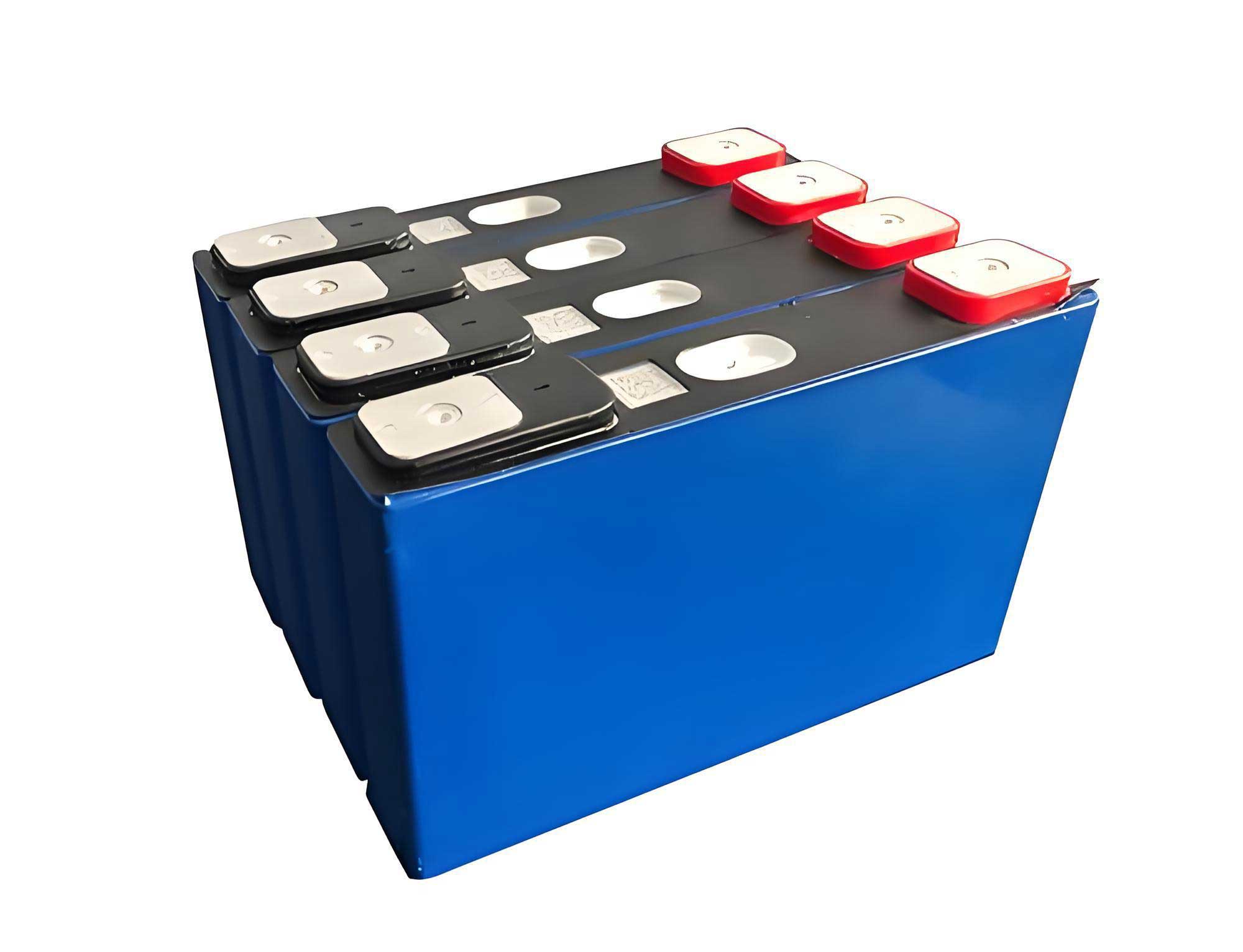
My study centers on a commercial 22 Ah LiFePO4 battery cell with a laminated structure, where electrodes and separators are stacked to form a pouch-type configuration. The cell dimensions are 200 mm × 180 mm × 7.7 mm, with positive and negative tabs for current collection. The internal materials include aluminum foil for the positive electrode, copper foil for the negative electrode, and a polymer separator, all encapsulated in an aluminum-plastic film. Understanding the thermal characteristics of this LiFePO4 battery begins with analyzing its heat generation sources during operation.
In a LiFePO4 battery, heat is primarily generated from irreversible and reversible processes. The total heat generation rate per unit volume, denoted as \( q \), can be expressed as the sum of reaction heat, polarization heat, Joule heat, and side reaction heat. However, side reactions are negligible under normal conditions. Thus, based on the Bernardi model, the heat generation rate for a LiFePO4 battery is given by:
$$ q = \frac{I}{V_b} \left[ (E_0 – U) + T \frac{dE_0}{dT} \right] $$
where \( I \) is the current (positive for discharge, negative for charge), \( V_b \) is the battery volume, \( E_0 \) is the open-circuit voltage, \( U \) is the terminal voltage, and \( T \) is the absolute temperature. The term \( (E_0 – U) \) represents irreversible Joule heating due to internal resistance, while \( T \frac{dE_0}{dT} \) accounts for reversible entropic heat. For my LiFePO4 battery, I measured the ohmic resistance \( R_0 \) as 0.7 mΩ, allowing simplification: \( (E_0 – U) = I R_0 \). The temperature coefficient \( \frac{dE_0}{dT} \) is taken as 0.04 mV/K based on literature. This model is essential for simulating the thermal response of the LiFePO4 battery under various operating conditions.
To accurately model heat transfer, I determined key thermophysical parameters: density, specific heat capacity, and thermal conductivity. The average density \( \rho \) of the LiFePO4 battery was calculated from material compositions, yielding 2194 kg/m³. For specific heat capacity \( C_p \), I conducted an experimental setup using a heating plate attached to the battery surface, insulated to minimize heat loss. By applying a constant power and monitoring temperature rise, I derived \( C_p \) from:
$$ C_p = \frac{P}{m \frac{dT}{dt}} $$
where \( P \) is the heating power, \( m \) is the battery mass, and \( \frac{dT}{dt} \) is the temperature gradient over time. The result for the LiFePO4 battery was 1083.75 J/(kg·K). Thermal conductivity was estimated using a series resistance method, considering anisotropic properties due to layered materials. The equivalent thermal conductivities along different axes are:
$$ \lambda_x = \frac{L}{\sum \frac{L_i}{\lambda_i}}, \quad \lambda_y = \lambda_z = \frac{\sum A_i \lambda_i}{\sum A_i} $$
where \( L \) is total thickness, \( L_i \) and \( \lambda_i \) are thickness and conductivity of each layer, and \( A_i \) is cross-sectional area. The values for internal materials are summarized in Table 1.
| Material | Thermal Conductivity (W/m·K) |
|---|---|
| Positive Electrode (Aluminum) | 237 |
| Negative Electrode (Copper) | 386 |
| Separator | 0.356 |
| Aluminum Foil | 237.69 |
| Copper Foil | 398.12 |
From these, I computed the average thermal conductivities for the LiFePO4 battery: \( \lambda_x = 0.905 \, \text{W/m·K} \) in the thickness direction, and \( \lambda_y = \lambda_z = 2.687 \, \text{W/m·K} \) in the planar directions. These parameters are crucial for building a reliable thermal model of the LiFePO4 battery.
The heat transfer in the LiFePO4 battery is governed by the energy conservation equation. Assuming homogeneous material properties and uniform current distribution, the transient thermal model in three dimensions is:
$$ \rho C_p \frac{\partial T}{\partial \tau} = \lambda_x \frac{\partial^2 T}{\partial x^2} + \lambda_y \frac{\partial^2 T}{\partial y^2} + \lambda_z \frac{\partial^2 T}{\partial z^2} + q $$
where \( \tau \) is time, and \( q \) is the volumetric heat generation rate from the Bernardi model. Boundary conditions consider convection at the battery surface:
$$ -\lambda \frac{\partial T}{\partial n} = \alpha (T – T_f) $$
with \( \alpha \) as the convection heat transfer coefficient, \( T_f \) as ambient temperature, and \( n \) denoting the normal direction. Initial conditions set the battery temperature to ambient, e.g., \( T(x,y,z,0) = 25^\circ \text{C} \). This formulation allows for simulating the LiFePO4 battery’s temperature distribution under various cooling scenarios.
To implement the CFD simulation, I created a geometric model of the LiFePO4 battery cell using CAD software, matching actual dimensions. The model was imported into FloTHERM, where I assigned the derived thermophysical parameters. The heat generation rate was calculated for specific operating conditions. For instance, at a 0.4 C charge rate (8.8 A) and 25°C ambient, the heat generation rate is:
$$ q_{0.4C} = \frac{I}{V_b} \left( I R_0 + T \frac{dE_0}{dT} \right) = 574 \, \text{W/m}^3 $$
leading to a total heat output of 0.16 W. Similarly, at a 1 C charge rate (22 A), the heat generation rate increases to 2168 W/m³, with total heat of 0.6 W. The CFD simulations produced temperature fields, revealing that the maximum temperature occurs near the positive tab due to lower thermal conductivity of aluminum compared to copper. This aligns with the inherent properties of the LiFePO4 battery materials.
Validation of the CFD model was performed through non-contact thermal testing. I placed the LiFePO4 battery in a 25°C environment and charged it at 1 C under natural convection. After reaching steady state, I measured surface temperatures at multiple points using an infrared camera. The results, compared against simulation outputs, are shown in Table 2.
| Measurement Point | Experimental Temperature (°C) | Simulated Temperature (°C) | Error (°C) |
|---|---|---|---|
| A (Near Positive Tab) | 27.9 | 28.2 | 0.3 |
| B (Center) | 28.2 | 28.1 | 0.1 |
| C (Side Edge) | 28.1 | 27.8 | 0.3 |
| D (Near Negative Tab) | 27.4 | 27.8 | 0.4 |
The errors are within 0.5°C, confirming the accuracy of my thermal model for the LiFePO4 battery. This validation step is vital for relying on simulation results to explore thermal management strategies.
I investigated the impact of different cooling methods on the LiFePO4 battery’s thermal performance by varying the convection coefficient \( \alpha \) in simulations. Four scenarios were analyzed: natural cooling (\( \alpha = 5 \, \text{W/m}^2\cdot\text{K} \)), moderate forced air cooling (\( \alpha = 10 \, \text{W/m}^2\cdot\text{K} \)), intense forced air cooling (\( \alpha = 25 \, \text{W/m}^2\cdot\text{K} \)), and water cooling (\( \alpha = 390 \, \text{W/m}^2\cdot\text{K} \)). All simulations assumed a 1 C charge rate at 25°C ambient. The steady-state temperature distributions are summarized in Table 3, highlighting maximum temperatures and key observations.
| Cooling Method | Convection Coefficient (W/m²·K) | Maximum Battery Temperature (°C) | Temperature Reduction vs. Natural Cooling (°C) |
|---|---|---|---|
| Natural Cooling | 5 | 28.5 | 0 |
| Moderate Forced Air | 10 | 27.8 | 0.7 |
| Intense Forced Air | 25 | 27.4 | 1.1 |
| Water Cooling | 390 | 27.1 | 1.4 |
The data shows that enhanced convection significantly lowers the operating temperature of the LiFePO4 battery. Forced air cooling, especially at higher intensities, improves heat dissipation substantially, while water cooling offers marginal additional benefit but adds complexity and cost. This analysis underscores the importance of selecting an appropriate cooling system for LiFePO4 battery packs based on thermal requirements and practical constraints.
Further, I derived insights into heat generation dynamics. The heat rate equation can be expanded for specific conditions. For example, during charging, the current \( I \) is negative, so the heat generation rate becomes:
$$ q_{\text{charge}} = \frac{-|I|}{V_b} \left( -|I| R_0 + T \frac{dE_0}{dT} \right) = \frac{|I|}{V_b} \left( |I| R_0 – T \frac{dE_0}{dT} \right) $$
This indicates that reversible heat may offset Joule heat under certain conditions, affecting the net heating of the LiFePO4 battery. To generalize, I formulated the heat generation for any state of charge (SOC) by incorporating voltage variations. However, for simplicity in my CFD model, I assumed constant internal resistance and linear voltage behavior, which suffices for thermal analysis of the LiFePO4 battery in typical operating ranges.
In terms of thermal design, the anisotropic thermal conductivity of the LiFePO4 battery implies that heat spreads more easily in-plane than through thickness. This influences how cooling should be applied—for instance, attaching heat sinks to broad surfaces may be more effective for a LiFePO4 battery. Additionally, the higher temperature near the positive tab suggests that thermal interface materials or targeted cooling could mitigate hotspots in LiFePO4 battery packs.
To deepen the analysis, I considered transient effects during rapid charging. Using the CFD model, I simulated temperature rise over time for the LiFePO4 battery under 1 C charging. The temperature evolution follows:
$$ T(t) = T_f + \frac{q}{\rho C_p} \int_0^t e^{-\frac{\alpha A}{\rho C_p V} (t-\xi)} d\xi $$
where \( A \) is surface area and \( V \) is volume. This integral approach approximates the warming curve, but full CFD provides precise spatial distributions. My simulations showed that the LiFePO4 battery reaches steady state within 30 minutes, consistent with experimental observations.
Another aspect is the effect of ambient temperature on the LiFePO4 battery’s thermal behavior. I ran simulations at 10°C, 25°C, and 40°C environments, keeping the 1 C charge rate. The results, encapsulated in Table 4, demonstrate that higher ambient temperatures exacerbate heating, reinforcing the need for robust thermal management in LiFePO4 battery systems used in varied climates.
| Ambient Temperature (°C) | Maximum Battery Temperature (°C) with Natural Cooling | Heat Generation Rate (W/m³) |
|---|---|---|
| 10 | 24.8 | 2150 |
| 25 | 28.5 | 2168 |
| 40 | 32.3 | 2185 |
The slight increase in heat generation rate with temperature is due to the \( T \frac{dE_0}{dT} \) term, but the dominant effect is reduced heat dissipation at higher ambients. This highlights the sensitivity of LiFePO4 battery performance to environmental conditions.
In practical applications, such as electric vehicles, LiFePO4 battery packs consist of multiple cells, where thermal interactions complicate management. My single-cell model can be extended to module-level simulations by incorporating inter-cell spacing and cooling channels. For example, the overall heat balance for a pack with \( N \) cells is:
$$ Q_{\text{total}} = N \cdot q V_b + Q_{\text{interconnect}} $$
where \( Q_{\text{interconnect}} \) accounts for additional losses from busbars. CFD simulations of such assemblies can optimize airflow or liquid cooling layouts for LiFePO4 battery packs, ensuring uniform temperatures and longevity.
Moreover, I explored the role of battery geometry in thermal behavior. Compared to cylindrical cells, the pouch-type LiFePO4 battery has a larger surface-to-volume ratio, favoring convection cooling. However, its layered structure creates thermal resistance anisotropies, as captured in my model. Alternative designs, like incorporating thermal pads or phase-change materials, could enhance heat dissipation for LiFePO4 batteries in high-demand scenarios.
From a safety perspective, thermal runaway in LiFePO4 batteries is less common than in other lithium-ion chemistries, but it remains a risk under extreme conditions. My heat generation model includes only normal operation; for abuse scenarios, additional terms for exothermic side reactions would be needed. Nevertheless, maintaining temperatures below 45°C through effective cooling is crucial for safe operation of LiFePO4 battery systems.
In conclusion, my comprehensive study on the LiFePO4 battery provides a framework for thermal analysis and simulation. I developed a heat generation model based on the Bernardi equation, identified key thermophysical parameters through experimental and calculative methods, and built a validated CFD model using FloTHERM. The results demonstrate that cooling methods significantly influence the thermal performance of LiFePO4 batteries, with forced air cooling offering a balanced improvement over natural convection. The insights gained can guide the design of thermal management systems for LiFePO4 battery packs in electric vehicles, ensuring safety, efficiency, and durability. Future work could integrate electro-thermal coupling for more dynamic simulations or explore novel cooling techniques tailored for LiFePO4 battery applications.
Throughout this investigation, the importance of accurate thermal modeling for LiFePO4 batteries has been evident. By leveraging CFD tools and experimental validation, engineers can predict temperature distributions and optimize cooling strategies, ultimately enhancing the reliability of energy storage solutions. The LiFePO4 battery, with its favorable thermal stability, benefits from such detailed analyses to maximize its potential in sustainable transportation.