
In recent years, the rapid development of clean energy sources, such as photovoltaic and wind power, has driven the need for energy storage systems to stabilize grid fluctuations. Among these, LiFePO4 battery energy storage stations have gained significant attention due to their high energy density, long cycle life, and relatively good safety profile. However, safety concerns, particularly thermal runaway caused by overcharging, remain a critical issue that can lead to fires, explosions, and toxic gas emissions, posing severe risks to personnel and infrastructure. In this study, we investigate the characteristic parameters of LiFePO4 battery overcharge thermal failure to develop effective early warning strategies. Our focus is on analyzing gas emissions, voltage changes, temperature variations, and other key indicators during the early stages of thermal failure. By employing a two-stage overcharge method on a 100 A·h LiFePO4 battery, we aim to identify reliable warning signals and assess the risk status after charging cessation. This research contributes to enhancing the safety of LiFePO4 battery energy storage systems by providing insights into failure mechanisms and proposing a multi-level warning approach.
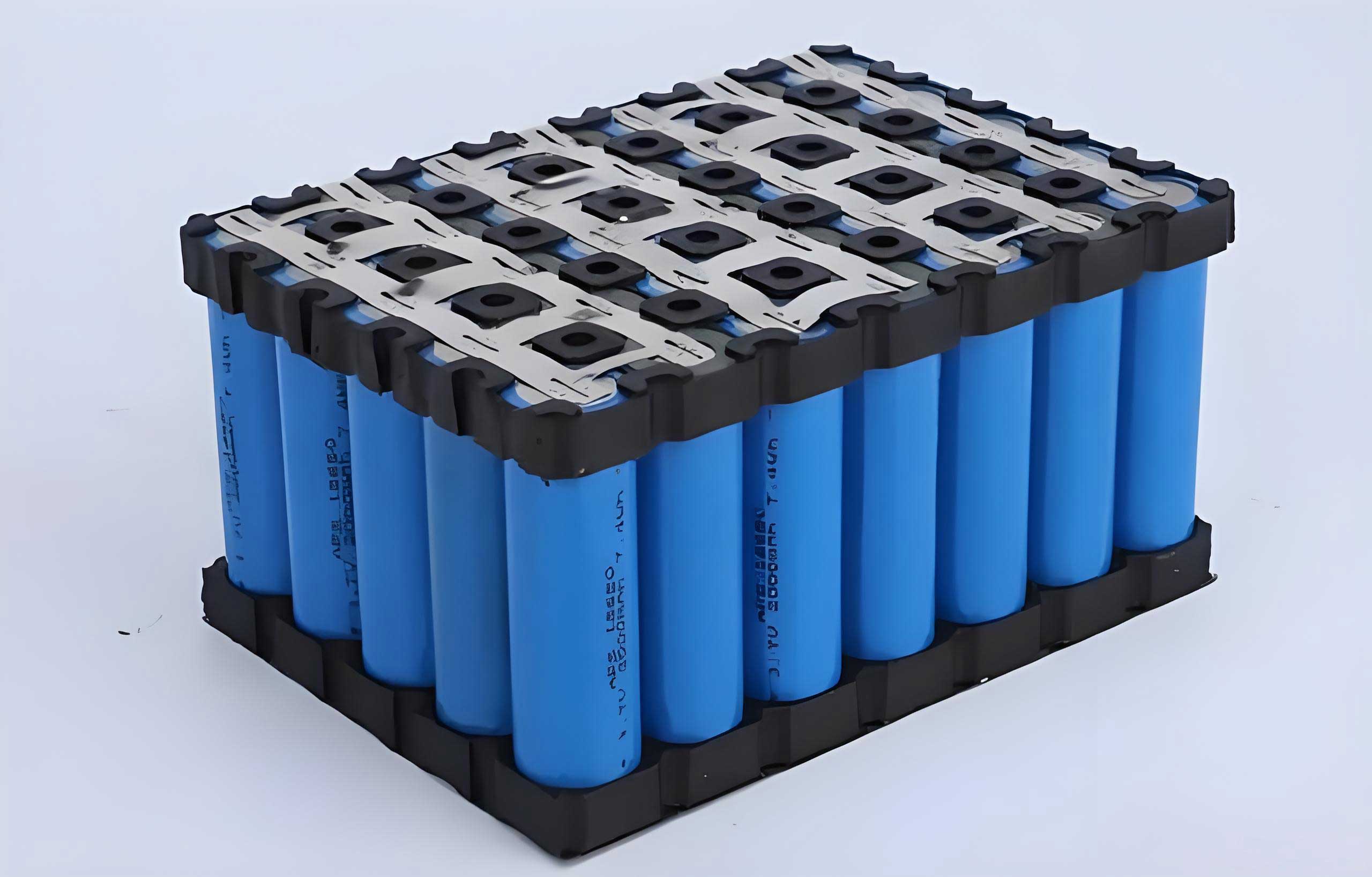
The experimental setup involved a 100 A·h LiFePO4 battery with dimensions of 160 mm × 118.5 mm × 50 mm and a mass of 2.0 kg. Key parameters of the LiFePO4 battery are summarized in Table 1. The electrolyte composition included LiPF6 as the lithium salt, with solvents such as dimethyl carbonate (DMC), diethyl carbonate (DEC), ethyl methyl carbonate (EMC), and ethylene carbonate (EC). We conducted overcharge experiments in a semi-enclosed chamber (1400 mm × 700 mm × 700 mm) equipped with a battery testing system, temperature sensors, gas detectors, and visual monitoring devices. Gas emissions were analyzed using electrochemical gas detectors for H2, CO, CO2, and HF, along with a gas chromatograph (GC) for detailed composition analysis. The overcharge process was divided into two stages: the first stage involved constant current charging at 0.5C (50 A) until the voltage reached 20 V, simulating early thermal failure; the second stage resumed charging at 0.1C (10 A) after a 30-minute interval until thermal runaway occurred. This two-stage approach allowed us to explore warning effectiveness and post-charging risks in LiFePO4 battery systems.
| Parameter | Value |
|---|---|
| Rated Capacity (A·h) | 100 |
| Operating Voltage (V) | 2.5–3.65 |
| Internal Resistance (1 kHz) (mΩ) | 0.2–0.5 |
| Battery Mass (kg) | 2.0 |
During the first overcharge stage, we observed distinct voltage phases. Initially, the voltage rapidly increased to 4.38 V, followed by a slow rise to 5.06 V at a rate of approximately 0.01 V/s, accompanied by noticeable battery expansion. At 835 seconds, the voltage peaked and began to decline, with the safety valve opening at 1,178 seconds (voltage at 4.85 V), releasing smoke and brown electrolyte. Subsequently, the voltage rebounded and entered a second rapid rise phase, reaching 20 V at 1,350 seconds with a peak rate of 1.2 V/s. The overcharge capacity at this point was 15.7% state of charge (SOC). In the second stage, voltage surged from 5.69 V to 18.82 V within 220 seconds, then dropped to 0 V at 510 seconds, indicating an internal short circuit and thermal runaway. The charging amount was only 1.5% SOC, highlighting that even after stopping overcharge, LiFePO4 batteries remain at risk due to residual reactions.
Temperature monitoring revealed that during the first stage, surface temperatures increased slowly before safety valve opening, with the highest temperature of 59.1°C at the side. After charging stopped at 1,350 seconds, temperatures continued to rise for about 5 minutes, reaching up to 85.7°C at the negative terminal, before gradually decreasing. This post-charging temperature rise suggests ongoing exothermic side reactions within the LiFePO4 battery. In the second stage, temperatures rose steadily until the internal short circuit, where the rate exceeded 1°C/s, peaking at 2.3°C/s and reaching 162.6°C at the front surface. The significant temperature gradient between the interior and exterior (over 110°C) underscores the limitations of external temperature sensors for early warning in LiFePO4 battery systems.
Gas detection results showed that H2 was the earliest and most abundant gas emitted from the LiFePO4 battery. After safety valve opening, H2 concentration reached the alarm threshold within 5 seconds, while CO followed after 13 seconds. CO2 levels increased steadily but at a slower rate. GC analysis confirmed that H2 accounted for over 62% of total gas volume at its peak, making it a prime candidate for early warning. CO and hydrocarbon gases, particularly C2H4, were also significant, with C2H4 comprising 78.5% of hydrocarbons at its peak. The presence of C2H2 was detected later, indicating high internal temperatures. The gas evolution patterns are linked to chemical reactions during overcharge. For instance, lithium dendrite formation and reaction with binders produce H2:
$$ \text{CH}_2\text{CF}_2 + \text{Li} \rightarrow \text{CH}_2\text{CF}_2\text{Li} + \text{LiF} + \text{H}_2 $$
Further reactions with electrolyte solvents generate CO and hydrocarbons:
$$ 4\text{Li} + \text{C}_4\text{H}_8\text{O}_3 (\text{EMC}) \rightarrow \text{CH}_3\text{CHOCOOLi} + \text{CH}_3\text{CH}_2\text{Li} + \text{CH}_4 $$
$$ 2\text{Li} + \text{C}_3\text{H}_6\text{O}_3 (\text{DMC}) \rightarrow \text{Li}_2\text{CO}_3 + \text{C}_2\text{H}_6 $$
$$ 2\text{Li} + \text{C}_3\text{H}_4\text{O}_3 (\text{EC}) \rightarrow \text{Li}_2\text{CO}_3 + \text{C}_2\text{H}_4 $$
Decomposition of SEI膜 components and cathode materials at elevated temperatures releases O2, which reacts with solvents to form CO2:
$$ \frac{5}{2}\text{O}_2 + \text{C}_3\text{H}_4\text{O}_3 (\text{EC}) \rightarrow 2\text{H}_2\text{O} + 3\text{CO}_2 $$
These exothermic reactions contribute to heat accumulation, leading to separator shutdown and eventual internal short circuit in the LiFePO4 battery. Our analysis indicates that stopping overcharge during the second voltage rise phase (4.85–20 V) can prevent thermal runaway, but residual lithium dendrites may sustain reactions, causing delayed temperature increases. Therefore, early warning systems for LiFePO4 batteries should integrate multiple parameters.
Based on our findings, we propose a hierarchical warning strategy for LiFePO4 battery energy storage systems. Before safety valve opening, voltage monitoring during the first rise phase (3.65–5.06 V) serves as the primary warning. After valve opening, H2 and CO are used as first-level warnings due to their early appearance and high concentrations. Hydrocarbon gases, such as C2H4, act as second-level warnings. The second voltage rise phase (4.85–20 V) provides a third-level warning, signaling imminent thermal failure. This multi-parameter approach enhances reliability and allows for timely intervention to mitigate risks in LiFePO4 battery setups.
To quantify gas emissions, Table 2 summarizes GC data during the first overcharge stage. The data highlights the dominance of H2 and the progressive increase in hydrocarbon species, reinforcing the importance of gas-based monitoring for LiFePO4 battery safety.
| Stage | H2 (%) | CO (%) | CO2 (%) | CH4 (%) | C2H6 (%) | C2H4 (%) | C2H2 (%) | C3H8 (%) | C3H6 (%) | C4H10 (%) |
|---|---|---|---|---|---|---|---|---|---|---|
| Before Valve Open | 0 | 0 | 0.1112 | 0 | 0 | 0 | 0 | 0 | 0 | 0 |
| After Valve Open | 0.1724 | 0.0309 | 0.2426 | 0.0073 | 0.0034 | 0.0036 | 0 | 0.0002 | 0 | 0.0003 |
| 5 Minutes Later | 0.2235 | 0.0375 | 0.2950 | 0.0096 | 0.0052 | 0.0059 | 0 | 0.0002 | 0 | 0.0005 |
| 10 Minutes Later | 0.3596 | 0.0522 | 0.4284 | 0.0140 | 0.0078 | 0.0252 | 0.0004 | 0.0004 | 0.0002 | 0.0003 |
| 15 Minutes Later | 0.4880 | 0.0949 | 0.7232 | 0.0225 | 0.0118 | 0.1323 | 0 | 0.0007 | 0.0010 | 0.0018 |
| 20 Minutes Later | 0.4724 | 0.0937 | 0.7002 | 0.0220 | 0.0134 | 0.1492 | 0.0009 | 0.0008 | 0.0012 | 0.0020 |
In conclusion, our study on LiFePO4 battery overcharge thermal failure reveals critical characteristic parameters that can inform safety protocols. The LiFePO4 battery exhibited voltage surges up to 20 V before thermal runaway, with effective warning possible during the second rise phase. However, post-charging temperature increases due to residual lithium dendrite reactions emphasize the need for prompt action. Gas emissions, particularly H2, provide early warnings at least 3 minutes before failure, supported by CO and hydrocarbon gases like C2H4. The proposed warning strategy integrates voltage, gas, and temperature monitoring to enhance LiFePO4 battery safety in energy storage applications. Future work should explore real-time sensor integration and broader validation across different LiFePO4 battery capacities and conditions to optimize reliability. Overall, this research underscores the importance of multi-parameter monitoring in mitigating risks associated with LiFePO4 battery thermal failure, contributing to safer and more efficient energy storage systems.
Further analysis of the chemical kinetics involved in LiFePO4 battery overcharge can be modeled using Arrhenius equations to predict reaction rates. For example, the rate of H2 production from lithium dendrite reactions can be expressed as:
$$ r = A \exp\left(-\frac{E_a}{RT}\right) $$
where \( r \) is the reaction rate, \( A \) is the pre-exponential factor, \( E_a \) is the activation energy, \( R \) is the gas constant, and \( T \) is the temperature in Kelvin. This model helps quantify the exothermic processes that drive thermal runaway in LiFePO4 batteries. Additionally, heat generation during overcharge can be described by the energy balance equation:
$$ \frac{dQ}{dt} = I^2 R + \sum \Delta H_i r_i $$
where \( \frac{dQ}{dt} \) is the heat generation rate, \( I \) is the current, \( R \) is the internal resistance, and \( \Delta H_i \) and \( r_i \) are the enthalpy change and rate of side reaction \( i \), respectively. This equation highlights the contributions of joule heating and chemical reactions to temperature rise in LiFePO4 batteries.
To illustrate the voltage phases, we can define the overcharge process in terms of state of charge (SOC) and voltage thresholds. For a LiFePO4 battery, the voltage during overcharge follows a piecewise function:
$$ V(t) =
\begin{cases}
V_0 + k_1 t & \text{for } t < t_1 \\
V_1 + k_2 (t – t_1) & \text{for } t_1 \leq t < t_2 \\
V_2 – k_3 (t – t_2) & \text{for } t_2 \leq t < t_3 \\
V_3 + k_4 (t – t_3) & \text{for } t_3 \leq t < t_4
\end{cases} $$
where \( V_0 \) is the initial voltage, \( k_i \) are rate constants, and \( t_i \) are time points corresponding to phase transitions. This model aligns with our experimental observations for the LiFePO4 battery, where \( t_3 \) marks the start of the second rapid rise phase critical for warning.
In terms of gas emissions, the concentration of H2 over time can be approximated by a sigmoidal growth curve, reflecting accelerated production as temperature rises:
$$ [\text{H}_2](t) = \frac{C_{\text{max}}}{1 + \exp(-k(t – t_0))} $$
where \( C_{\text{max}} \) is the maximum concentration, \( k \) is the growth rate, and \( t_0 \) is the inflection point. This equation underscores the rapid increase in H2 that makes it an effective warning signal for LiFePO4 battery thermal failure.
Our experimental data also suggests that the LiFePO4 battery’s internal resistance increases significantly during the second voltage rise phase due to separator shutdown. This can be represented as:
$$ R(t) = R_0 + \alpha \exp(\beta t) $$
where \( R_0 \) is the initial resistance, and \( \alpha \) and \( \beta \) are constants related to material properties. The exponential rise contributes to voltage spikes and heat accumulation, ultimately leading to internal short circuit in the LiFePO4 battery.
For practical applications, we recommend implementing gas sensors with thresholds based on our findings. For instance, H2 alarms should trigger at 0.1% concentration, while CO alarms at 0.03%, providing a buffer before critical levels are reached in LiFePO4 battery systems. Temperature sensors should monitor gradients exceeding 50°C between interior and exterior surfaces, indicating severe side reactions. Voltage monitoring systems must detect rates above 0.5 V/s during the second rise phase to initiate emergency protocols for LiFePO4 batteries.
In summary, the LiFePO4 battery’s behavior under overcharge conditions is complex, involving interrelated electrical, thermal, and chemical processes. Our study provides a comprehensive framework for understanding these interactions and developing robust safety measures. By prioritizing H2 detection and multi-parameter warnings, we can enhance the reliability of LiFePO4 battery energy storage, supporting the global transition to sustainable energy. Continued research on LiFePO4 battery failure mechanisms will further refine these strategies, ensuring safer deployment in large-scale applications.