
The relentless depletion of conventional fossil fuels and their escalating environmental impact have catalysed a global shift towards sustainable energy solutions. Within the maritime sector, this imperative is driving innovation towards ‘green shipping’. Among the various renewable alternatives, photovoltaic (PV) technology stands out due to its cleanliness, abundance, and increasing cost-effectiveness. The integration of a solar system onboard vessels presents a significant pathway to reduce operational carbon footprint, auxiliary fuel consumption, and enhance energy efficiency. This paper explores the application, design, and implications of a dedicated solar photovoltaic power system, drawing from a detailed case study of an 800PCC (Pure Car Carrier) roll-on/roll-off vessel designed for inland waterways. The analysis underscores the technical feasibility, regulatory considerations, and tangible benefits, particularly in improving the Energy Efficiency Design Index (EEDI), realized through the strategic deployment of a marine solar system.
1. Regulatory Framework and Application Status of Marine Solar Systems
The adoption of solar energy in maritime applications is governed by a framework of classification society rules and practical limitations. Currently, the power output from a typical marine solar system is constrained by available installation area and conversion efficiency. Consequently, its primary role is not for main propulsion but for auxiliary power generation, supporting hotel loads, lighting, and navigational equipment. This is explicitly reflected in regulations such as the “Rules for Building Steel Inland Waterways Ships,” which stipulate that solar cells should only serve as an auxiliary power source.
Therefore, the application of solar systems as a primary or hybrid power source is predominantly feasible for specific vessel types. These include small sightseeing boats, tourist vessels, and ferries operating on fixed, short-distance routes in favorable hydrological conditions. Such vessels typically have low displacement, modest speed requirements, and limited high-power electrical demands beyond essential lighting and navigation. For larger merchant vessels, the solar system functions as a supplementary energy source, contributing to the overall power grid and reducing the running hours of diesel-driven generators.
2. Inherent Advantages for RO-RO Vessels
The successful implementation of a solar system hinges critically on two factors: the availability of sufficient, unobstructed space for PV panel installation and the structural suitability of the installation platform. Many vessel types face challenges in this regard. Container ships and general cargo vessels have their main decks occupied by cargo and handling equipment. Tankers, while possessing large deck areas, impose stringent explosive atmosphere (Ex) requirements that complicate electrical installations. In contrast, RO-RO vessels, particularly car carriers, offer a distinct advantage. Their extensive, flat, and often unobstructed upper decks and topside areas provide an ideal platform for mounting large-scale PV arrays. This architectural characteristic makes the RO-RO ship type, including the 800PCC design, exceptionally well-suited for harnessing solar energy.
3. Case Study: Solar System Integration on an 800PCC RO-RO Vessel
3.1 Vessel Particulars and Design Philosophy
The subject vessel is an inland waterway pure car carrier operating between Shanghai and Chongqing. Its key parameters are summarized below:
| Parameter | Value | Unit |
|---|---|---|
| Length Overall | 110.00 | m |
| Moulded Depth | 5.20 | m |
| Maximum Breadth | 19.20 | m |
| Design Draft | 2.80 | m |
| Structural Draft | 3.00 | m |
| Class Notation | ★ CSAD RO-RO Cargo Ship, Inland A/B/C & J2; ★ CSMD BRC, Solar Auxiliary Power | |
The design philosophy centered on creating a ‘green ship,’ leading to the pursuit of class notation for solar auxiliary power. The integrated solar system was designed specifically to power a significant portion of the vessel’s lighting load, thereby directly reducing generator fuel consumption and associated emissions.
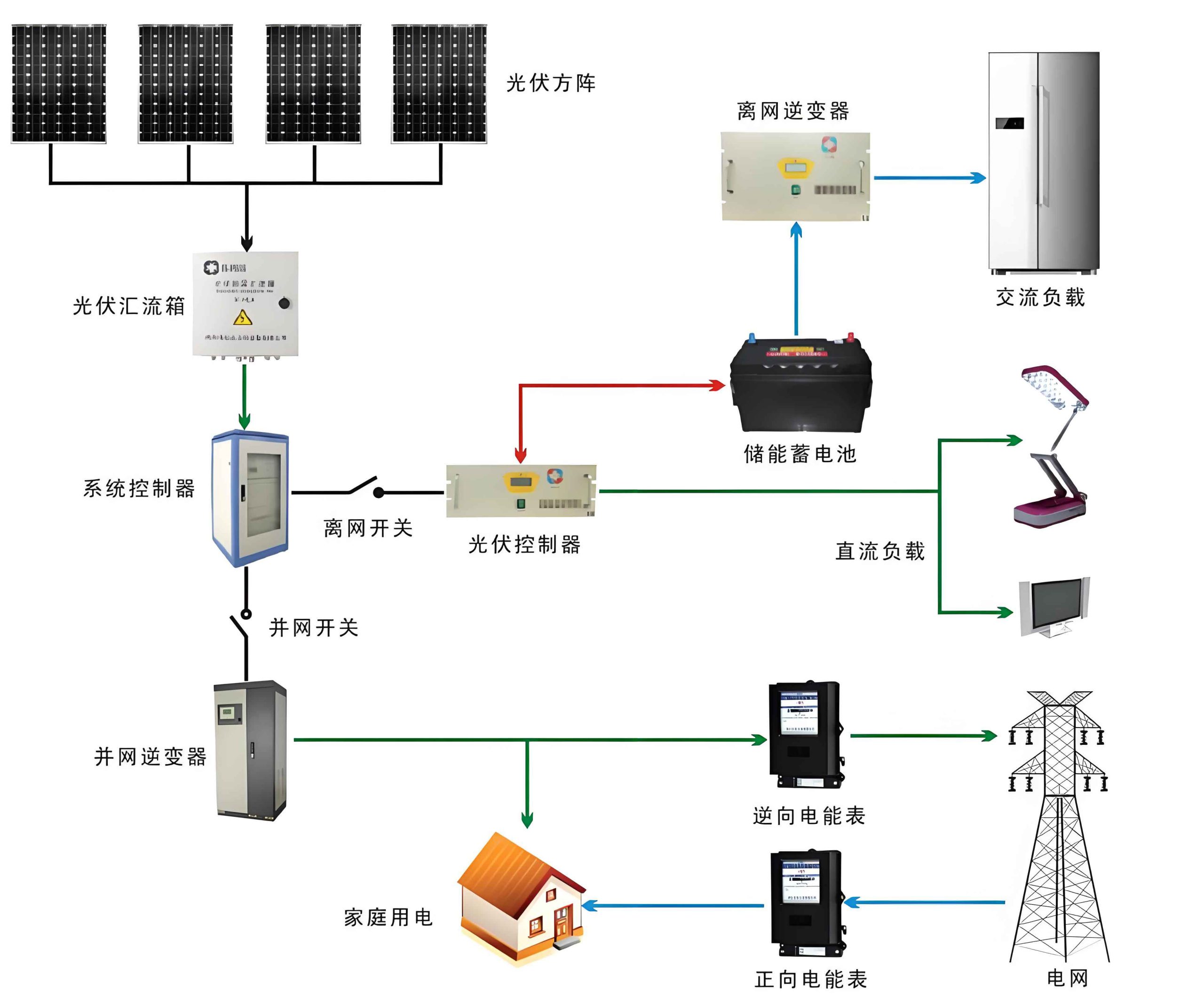
3.2 Architecture of the Off-Grid Solar Photovoltaic System
The vessel employs an off-grid PV system that operates independently but can interact with the main shipboard power grid. The core components and their topology are detailed as follows:
System Components:
- PV Array: Comprises 135 panels in a 15-series, 9-parallel (15S9P) configuration. Each panel has a peak power rating of 275 W.
- Lithium Iron Phosphate (LiFePO4) Battery Bank: Provides energy storage with a total capacity of 128 kWh. A Battery Management System (BMS) monitors and protects the bank.
- PV Controller: Performs Maximum Power Point Tracking (MPPT) to optimize energy harvest from the array. The MPPT algorithm can be conceptually represented as finding the voltage $V_{mp}$ that satisfies:
$$ \frac{dP}{dV} = \frac{d(V \cdot I(V))}{dV} = 0 $$
where $P$ is power, $V$ is voltage, and $I$ is current. - PV Inverter & Distribution Integrated Unit: Converts DC power from the controller/battery to stable 400V/50Hz AC power. It also contains automatic transfer switches for grid interaction.
- Energy Management System (EMS): The intelligent core that controls power flow based on availability and demand.
Key System Parameters & Calculations:
| Description | Calculation / Value | Unit |
|---|---|---|
| Total PV Array Peak Power | $P_{peak} = 135 \times 275$ | $37.13$ kWp |
| Theoretical Max. Daily Energy Yield | $E_{theo} = P_{peak} \times \text{Peak Sun Hours}$ | ~167 kWh (est.) |
| Practical Max. Daily Energy Yield | $E_{prac} = E_{theo} \times \eta_{system}$ | ~121 kWh |
| Battery Bank Usable Capacity (SOC 10-90%) | $C_{usable} = 128 \times 0.8$ | ~102.4 kWh |
3.3 Operational Modes of the Solar System
The solar system operates in three distinct modes, managed by the EMS:
1. Normal Solar Generation Mode: When solar irradiance is sufficient.
$$ P_{PV}(t) > P_{Load}(t) $$
The PV array powers the loads via the inverter. Surplus energy charges the battery bank:
$$ P_{Surplus}(t) = P_{PV}(t) – P_{Load}(t) = \frac{dE_{bat}}{dt} $$
where $E_{bat}$ is the energy stored in the battery.
2. Battery & Solar Hybrid Mode: When solar irradiance is low (e.g., cloudy day, night).
$$ P_{PV}(t) < P_{Load}(t) $$
The combined power from the PV array and the discharging battery supplies the load:
$$ P_{PV}(t) + P_{Bat, discharge}(t) = P_{Load}(t) $$
3. Grid Backup / Fault Mode: When the battery State of Charge (SOC) falls below a threshold (e.g., 15%) or the solar system faults. The Automatic Transfer Switch (ATS) connects the lighting distribution board directly to the vessel’s main AC grid, ensuring uninterrupted power. The ship’s generators then supply the load.
3.4 Safety Design in Compliance with Classification Guidelines
Adherence to classification society guidelines, such as the “Guidelines for Inspection of Solar Photovoltaic Systems and Lithium Iron Phosphate Battery Systems,” is paramount. Key safety measures implemented for the solar system include:
| Requirement | Implementation on 800PCC Vessel |
|---|---|
| Dedicated, ventilated battery room | Separate LiFePO4 battery room and PV electrical room were established. |
| Temperature monitoring and alarm | Temperature sensors installed in both rooms with audible/visual alarms on the bridge. |
| Fire protection | Battery room equipped with a fixed fire-extinguishing system (e.g., HFC-227ea). |
| Isolation from non-essential equipment | Battery rooms contain only system-critical components. |
3.5 Load Analysis for the Solar-Powered Lighting Circuit
The solar system was designed to power selected lighting circuits across the vessel. A detailed load analysis forms the basis for sizing the PV array and battery storage.
| Location | Power (kW) | Daily Operating Hours (h) | Utilization Factor | Daily Energy Demand (kWh) |
|---|---|---|---|---|
| Cargo Holds | 4.896 | 6 | 0.25 | 29.376 |
| Engine Room | 1.484 | 24 | 1.00 | 35.616 |
| Outdoor Areas | 0.588 | 4 | 0.17 | 2.352 |
| Accommodation (Indoor) | 2.162 | 24 | 1.00 | 51.888 |
| Forecastle Compartments | 0.270 | 5 | 0.21 | 1.350 |
| Total for Solar Circuit | Approximate Sum | ~120.6 | ||
The close alignment between the practical solar yield (~121 kWh) and the circuit’s daily demand (~120.6 kWh) demonstrates a well-balanced design where the solar system can theoretically meet the targeted load under optimal conditions.
4. Impact on Energy Efficiency Design Index (EEDI) and SEEMP
The primary quantifiable benefit of integrating a solar system is the improvement in the vessel’s energy efficiency metrics. For inland vessels, the Attained EEDI is calculated based on CO2 emissions relative to transport work. The formula, in its conceptual form, is:
$$ \text{Attained EEDI} = \frac{\sum_{i} (CF_i \cdot SFC_i \cdot P_i)}{\text{Capacity} \cdot \text{Reference Speed}} $$
where $CF_i$ is the carbon factor for the fuel, $SFC_i$ is the specific fuel consumption, and $P_i$ is the power of the i-th engine.
By powering the lighting load, the solar system directly reduces the required auxiliary generator power ($P_{aux}$) and its associated fuel consumption. This reduction lowers the numerator in the EEDI equation. For the 800PCC vessel:
| Metric | Value | Unit | Comparison |
|---|---|---|---|
| Calculated Attained EEDI | 52.878 | g/(t·n mile) | |
| Required EEDI for Green Ship-I ($RLV$) | 54.163 | g/(t·n mile) | Limit |
| Result | $\text{Attained EEDI} < RLV$ ➔ Vessel complies with Green Ship-I criteria. | ||
Furthermore, the solar system is a cornerstone of the vessel’s Ship Energy Efficiency Management Plan (SEEMP). The SEEMP outlines operational measures to improve efficiency, and the active utilization of the solar system is a key technological measure documented within it. The plan mandates maximizing the use of the solar system for lighting to minimize generator operation, thereby concretely reducing fuel consumption, NOx, and CO2 emissions throughout the vessel’s operational life.
5. Conclusion and Future Perspectives
The comprehensive study of the solar photovoltaic system onboard the 800PCC RO-RO vessel validates the technical and operational viability of such installations for specific ship types. The extensive deck space of RO-RO vessels provides a critical advantage for deploying a meaningful scale of PV capacity. The implemented off-grid system, with its sophisticated energy management and robust safety features, demonstrates a mature approach to integrating renewables into marine electrical grids.
The most significant outcome is the quantifiable improvement in the vessel’s environmental performance. By displacing auxiliary generator power, the solar system directly contributes to a lower Attained EEDI, enabling the vessel to meet stringent ‘Green Ship’ criteria. This case provides a valuable blueprint for the maritime industry. It proves that a well-designed solar system is not merely an symbolic green initiative but a functional asset that enhances energy efficiency, reduces operational costs, and mitigates environmental impact. Future developments in PV panel efficiency, energy storage density, and smarter shipboard microgrid management will only broaden the scope and amplify the benefits of solar systems in marine engineering, paving the way for their application on a wider range of vessel types and operational profiles.