
The transition towards a sustainable and low-carbon energy future necessitates innovative solutions for energy conversion and storage. Among various renewable sources, solar energy stands out due to its abundance and widespread availability. However, its inherent intermittency and variability pose significant challenges for direct grid integration. Converting solar energy into hydrogen—a clean, storable, and high-energy-density fuel—presents a compelling strategy to overcome these limitations, effectively creating a closed-loop, clean solar system. This process, often termed “solar fuel” generation, aligns perfectly with global decarbonization goals. Photovoltaic (PV) effect-based water splitting is one of the most promising technological pathways to achieve this conversion, primarily manifesting in two distinct configurations: photovoltaic-electrolyzer (PV-EC) systems and photoelectrochemical (PEC) cells. This article provides a detailed, first-person perspective review of the research progress in both these domains, focusing on materials, device architectures, efficiency enhancement strategies, and future challenges.
The fundamental principle uniting both pathways is the use of semiconductor materials to absorb sunlight and generate charge carriers that drive the water-splitting reaction. The overall reaction is:
$$2H_2O \xrightarrow[\text{Solar Energy}]{} 2H_2 + O_2$$
The thermodynamic potential required to split water is 1.23 V at standard conditions (25°C, 1 atm). However, due to kinetic overpotentials at the electrodes and various resistive losses in a practical solar system, the actual required voltage is significantly higher, typically between 1.6 V and 2.0 V. The overarching goal of research is to maximize the Solar-to-Hydrogen (STH) conversion efficiency, which is the ultimate metric for any practical solar system for hydrogen production. For a PV-EC system, STH is the product of the photovoltaic conversion efficiency (PCE) of the solar cell and the efficiency of the electrolyzer:
$$ \eta_{STH (PV-EC)} = \eta_{PCE} \times \eta_{Electrolyzer} $$
For an integrated PEC device, the STH efficiency is calculated directly from the photocurrent density ($J_{ph}$) at zero applied bias (for a standalone device) under standard solar illumination (AM 1.5G, 100 mW cm⁻²):
$$ \eta_{STH (PEC)} = \frac{ J_{ph} (mA/cm^2) \times 1.23 (V) }{ P_{in} (mW/cm^2) } \times 100\% $$
where a photocurrent density of ~8.1 mA cm⁻² corresponds to 10% STH efficiency.
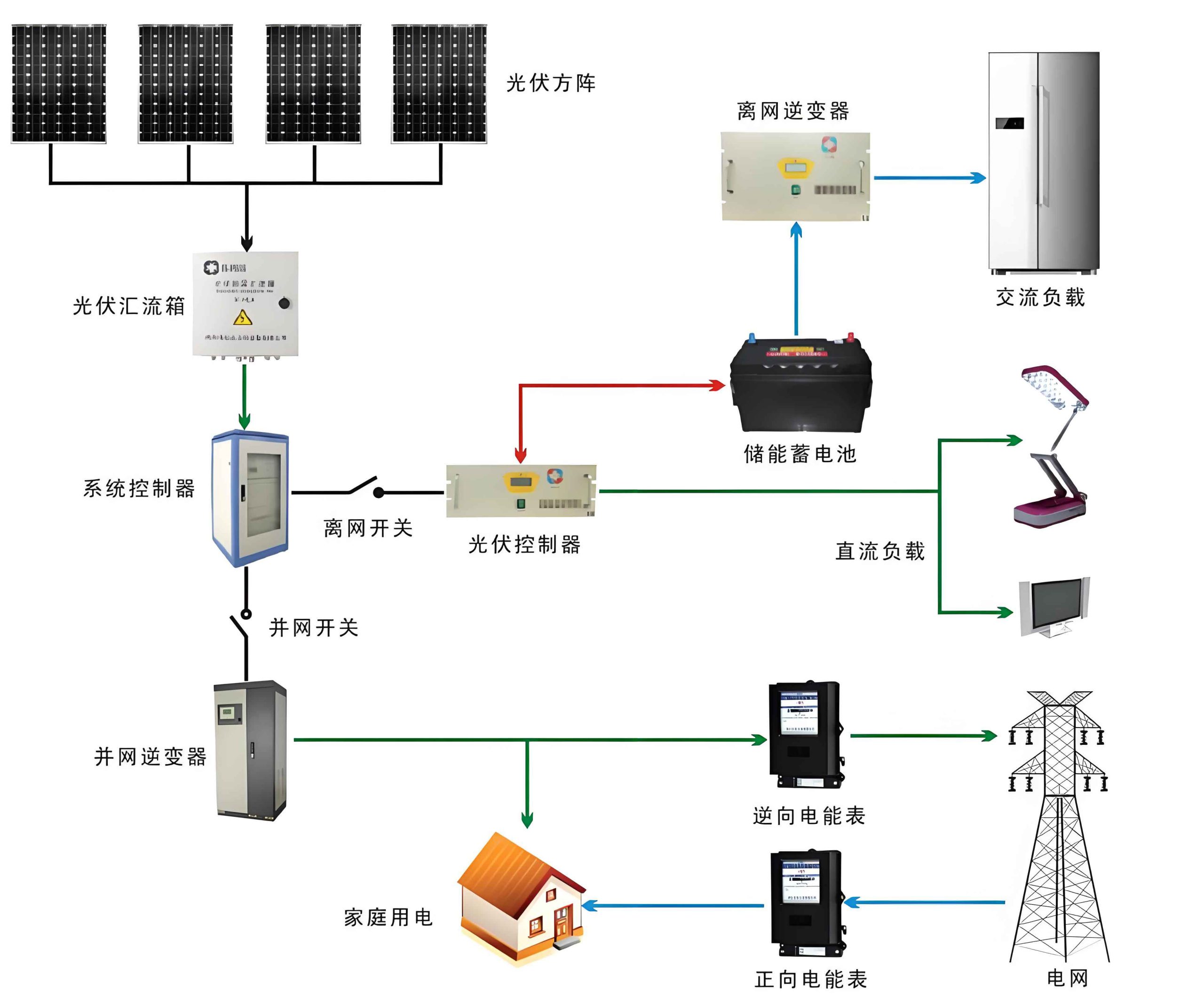
A PV-EC solar system is a decoupled architecture where a photovoltaic module generates electricity, which is then fed to a separate electrolyzer unit to produce hydrogen. This modular approach leverages the maturity of both PV and electrolysis technologies.
Photovoltaic-Electrolyzer (PV-EC) Systems
The design and integration of a PV-EC solar system involve critical considerations regarding the coupling method, the choice of solar cells, and the type of electrolyzer.
System Coupling and Power Management
The coupling between the PV array and the electrolyzer can be direct or indirect. Direct coupling offers simplicity and potentially higher overall STH by eliminating power conversion losses. However, it suffers from a significant impedance mismatch. The current-voltage (I-V) characteristics of a solar cell are non-linear and depend on irradiance and temperature, while the electrolyzer’s operational point is defined by its polarization curve. A direct connection often forces the system to operate away from the maximum power point (MPP) of the PV module, wasting energy. My analysis of such solar system configurations indicates that careful optimization of the number of series and parallel-connected cells can partially mitigate this, but perfect matching across all operating conditions is nearly impossible. Indirect coupling, using a power management unit with Maximum Power Point Tracking (MPPT) and DC-DC converters, ensures the PV array always operates at its MPP, delivering optimal power to the electrolyzer. Although this adds cost and complexity, it is generally considered essential for efficient and reliable large-scale solar system operation, as it stabilizes the power supply against fluctuating solar insolation.
Advances in Photovoltaic Components
The heart of the PV side of the solar system is the solar cell. Tremendous progress has been made beyond traditional crystalline silicon.
| Solar Cell Type | Typical PCE (Lab Record) | Key Advantages | Major Challenges for Solar System Integration |
|---|---|---|---|
| Silicon Heterojunction (SHJ) | ~26% | High efficiency, excellent stability, mature industry. | High material and processing cost; efficiency plateauing. |
| Perovskite Solar Cells (PSC) | >25% | Rapid efficiency growth, tunable bandgap, low-temperature processing. | Long-term stability under moisture/heat/light; lead toxicity concerns. |
| Tandem (e.g., Perovskite/Si) | >33% | Very high efficiency by utilizing broader solar spectrum. | Complex fabrication, interfacial issues, very high cost. |
| Dye-Sensitized (DSSC) | ~14% | Low cost, flexible, works under diffuse light. | Lower efficiency, long-term dye/electrolyte stability. |
| Organic (OSC) | >19% | Lightweight, flexible, semi-transparent, low-cost materials. | Poor operational stability, moderate efficiency. |
For a dedicated hydrogen-producing solar system, tandem cells are particularly attractive due to their high voltage output, which can better match the voltage requirements of an electrolyzer stack, reducing the need for extensive electrical series connections. However, the cost remains prohibitive. My perspective is that the future of PV for hydrogen lies in developing low-cost, stable, and efficient thin-film or emerging PV technologies specifically engineered for the current-voltage profile needed by electrolyzers, rather than solely chasing record PCE for grid applications.
Electrolyzer Technologies
The electrolyzer is the chemical engine of the solar system. Its efficiency and cost directly impact the levelized cost of hydrogen (LCOH).
| Electrolyzer Type | Key Electrolyte & Electrodes | Operating Conditions | Advantages | Disadvantages |
|---|---|---|---|---|
| Alkaline (AEL) | Liquid KOH/NaOH; Ni-based electrodes. | 60-90°C, <30 bar | Mature, low-cost catalysts, long lifetime. | Low current density, corrosive electrolyte, gas crossover, slow dynamics. |
| Proton Exchange Membrane (PEMEL) | Solid polymer membrane; Pt/Ir-based electrodes. | 50-80°C, <200 bar | High current density, high purity H₂, compact, rapid response. | High cost (Nafion, noble metals), acidic durability issues. |
| Anion Exchange Membrane (AEMEL) | Solid alkaline membrane; Non-noble metal electrodes. | 40-60°C, <35 bar | Potential for low cost (non-PGM catalysts), good performance. | Membrane stability and conductivity under high pH. |
| Solid Oxide (SOEL) | Ceramic oxide electrolyte; Ni-YSZ/ LSM electrodes. | 700-850°C | Very high efficiency (thermally assisted), can co-electrolyze H₂O/CO₂. | High temp. degradation, slow cycling, system complexity. |
For coupling with an intermittent solar system, PEMEL and AEMEL are favored due to their faster response and ability to handle variable load. The development of durable, high-performance membranes and non-precious metal catalysts (e.g., for the oxygen evolution reaction – OER) is critical to reducing the capital cost of these electrolyzers, making the entire PV-EC solar system more economically viable.
Photoelectrochemical (PEC) Water Splitting
PEC cells represent a more integrated solar system where light absorption, charge separation, and the electrochemical reaction occur within a single device. Upon illumination, a semiconductor photoelectrode generates electron-hole pairs. The holes drive the oxygen evolution reaction (OER) at the photoanode, while the electrons travel through an external circuit to the cathode to drive the hydrogen evolution reaction (HER).
$$ \text{Photoanode: } 2H_2O + 4h^+ \rightarrow O_2 + 4H^+ $$
$$ \text{Cathode: } 4H^+ + 4e^- \rightarrow 2H_2 $$
The major challenge lies in finding semiconductor materials that simultaneously satisfy the requirements for efficient light absorption, charge separation/transport, catalytic activity, and long-term stability in aqueous electrolytes. The design of an efficient PEC solar system revolves around engineering these photoelectrodes, primarily the photoanode.
Photoanode Materials and Nano-Engineering
n-Type semiconductors are typically used as photoanodes. Nanostructuring is a key strategy to enhance performance by increasing the surface area for reaction, reducing the distance charge carriers must travel to the interface, and improving light trapping.
1. Metal Oxide Semiconductors: These are widely studied due to their relative stability in oxidative environments.
- TiO₂: The benchmark material with excellent stability but a wide bandgap (~3.2 eV) limiting it to UV light. Strategies like doping (N, C) and sensitization with quantum dots (CdS, CdSe) are used to extend absorption into the visible spectrum.
- α-Fe₂O₃ (Hematite): Attractive due to its ideal ~2.1 eV bandgap, abundance, and stability in alkaline media. However, it suffers from poor conductivity, short hole diffusion length (<5 nm), and slow water oxidation kinetics. Nanostructuring (nanorods, porous films), element doping (Sn, Ti, Pt), and surface coating with OER catalysts (e.g., FeNiOx, Co-Pi) are essential to improve its performance.
- BiVO₄: A promising photoanode with a bandgap of ~2.4 eV. Its efficiency is limited by poor charge transport. Common enhancement methods include doping (Mo, W), constructing heterojunctions (e.g., with WO₃), and applying corrosion protection/co-catalyst layers.
- WO₃: Has a moderate bandgap (~2.6 eV) and good hole transport properties but is prone to photo-corrosion and has a less favorable valence band position for OER.
The performance of some common nanostructured photoanodes is summarized below:
| Material (Nanostructure) | Bandgap (eV) | Typical Photocurrent Density @ 1.23 VRHE (mA/cm²) | Key Enhancement Strategy |
|---|---|---|---|
| TiO₂ Nanotubes | ~3.2 | 0.5 – 1.5 (with sensitizer) | QD sensitization, doping |
| α-Fe₂O₃ Nanorods | ~2.1 | 1.0 – 4.0 | Sn doping, FeNiOx co-catalyst |
| BiVO₄ porous film | ~2.4 | 2.0 – 6.0 | Mo doping, WO₃ heterojunction, Co-Pi catalyst |
| WO₃ Nanoplates | ~2.6 | 1.5 – 3.0 | BiVO₄ heterojunction |
2. Heterojunction Engineering: Constructing heterojunctions between two semiconductors is a powerful method to improve charge separation. A common design is a “core-shell” structure where a narrow-bandgap absorber (e.g., BiVO₄) is coated with a wider-bandgap, more stable, and catalytically active material (e.g., TiO₂, FeOOH). The built-in electric field at the interface facilitates the separation of photogenerated electrons and holes. Tandem absorber structures, where a high-bandgap top absorber (for short-wavelength light) is stacked on a lower-bandgap bottom absorber (for long-wavelength light), can also significantly boost the photovoltage of the PEC solar system.
3. Emerging and Non-Oxide Materials: These include sulfides (e.g., CdS, CuInxGa(1-x)Se₂), nitrides (e.g., GaN, Ta3N5), and graphitic carbon nitride (g-C3N4). They often have superior light absorption properties but are generally less stable than oxides in aqueous environments and require protective coatings (e.g., TiO₂, NiO) for practical application in a durable solar system.
Photocathode Materials
p-Type semiconductors like Cu2O, Si, and InP are used as photocathodes for the HER. Cu2O is earth-abundant and has a suitable bandgap (~2.0 eV) but is notoriously unstable due to photocorrosion. The state-of-the-art approach involves depositing multi-functional protection layers (e.g., TiO₂/Al-doped ZnO) combined with HER catalysts (e.g., Pt, MoSx). The development of efficient, stable, and low-cost photocathodes remains a critical frontier for constructing unbiased, tandem PEC devices where a photoanode and a photocathode are connected in series.
Strategies for Enhancing PEC Solar System Efficiency
Beyond material selection, several system-level and operational strategies are crucial:
- Surface Catalysis: Depositing ultrathin, active OER or HER catalysts (co-catalysts) on the photoelectrode surface reduces the kinetic overpotential, thereby increasing the photocurrent at a given potential.
- Spectrum Management: Using tandem absorbers or optical designs like spectrally selective mirrors can more efficiently utilize the full solar spectrum.
- Electrolyte Engineering: The pH, ionic strength, and specific additives in the electrolyte can significantly affect reaction kinetics, stability, and the semiconductor’s flat-band potential. Alkaline electrolytes are often preferred for their compatibility with non-precious metal catalysts and many oxide photoanodes.
- PV-PEC Hybrid Systems: A promising configuration involves wire-connecting a high-efficiency multi-junction PV cell to a low-cost, robust PEC electrode. This leverages the excellent charge generation of the PV cell and the (potentially) lower-cost catalysis of the PEC electrode, decoupling the light absorption and catalytic functions. This hybrid solar system can achieve high STH while mitigating some material stability issues.
Conclusion and Future Perspective
The vision of a fully integrated, efficient, and economically competitive solar system for hydrogen production is steadily advancing. PV-EC systems benefit from technological maturity and modularity, with ongoing research focused on lowering the cost of high-efficiency solar cells (like perovskites and tandems) and developing durable, non-precious metal-based electrolyzers (PEMEL and AEMEL). The optimal coupling and power management for handling solar intermittency are also areas of active engineering development.
PEC systems offer the elegance of direct solar fuel generation but face more fundamental materials science challenges. The quest continues for ideal photoelectrode materials—or more realistically, material assemblies—that are highly efficient, stable for tens of thousands of hours, and made from abundant elements. The future likely lies in sophisticated heterostructures combining light absorbers, charge transport layers, corrosion protection barriers, and molecular catalysts, all orchestrated at the nanoscale.
Key cross-cutting priorities for the field include:
- Standardized Testing and Reporting: Implementing strict protocols for measuring and reporting STH efficiency and durability under realistic conditions is vital for comparing results and guiding research.
- Scale-up and Demonstration: Moving from lab-scale cells (<1 cm²) to panel-scale systems (>100 cm²) and eventually to pilot plants is essential to identify and solve engineering challenges related to sealing, current collection, gas separation, and long-term performance degradation.
- Techno-economic Analysis (TEA) & Life Cycle Assessment (LCA): Concurrent TEA and LCA must guide research directions, ensuring that efficiency gains translate into lower LCOH and a net positive environmental impact over the entire lifecycle of the solar system.
- Integration with Digital Tools: The use of AI and machine learning for high-throughput materials discovery, coupled with advanced in-situ characterization techniques to understand degradation mechanisms, will accelerate progress.
In my assessment, the pathway to commercialization may see PV-EC systems deployed first for large-scale, centralized solar hydrogen farms, while continued fundamental research on PEC and hybrid systems could lead to more integrated solutions in the longer term. The success of either—or a synergistic combination—will be a cornerstone for building a sustainable global energy infrastructure based on the ultimate renewable resource: sunlight.