
In recent years, the rapid development of renewable energy and electric vehicles has driven the widespread adoption of lithium-ion batteries due to their high energy density, long cycle life, and environmental friendliness. However, in most applications, numerous lithium-ion battery cells are connected in series and parallel to meet voltage and capacity requirements. This leads to a critical challenge: ensuring that all cells in a battery pack are charged and discharged simultaneously to maximize energy utilization. The inherent inconsistencies among lithium-ion battery cells, arising from manufacturing tolerances, aging, and temperature variations, result in state-of-charge (SOC) imbalances. These imbalances can reduce overall pack capacity, increase the risk of overcharging or over-discharging, and shorten battery lifespan. Therefore, effective battery management systems (BMS) with equalization circuits are essential for maintaining the health and performance of lithium-ion battery packs.
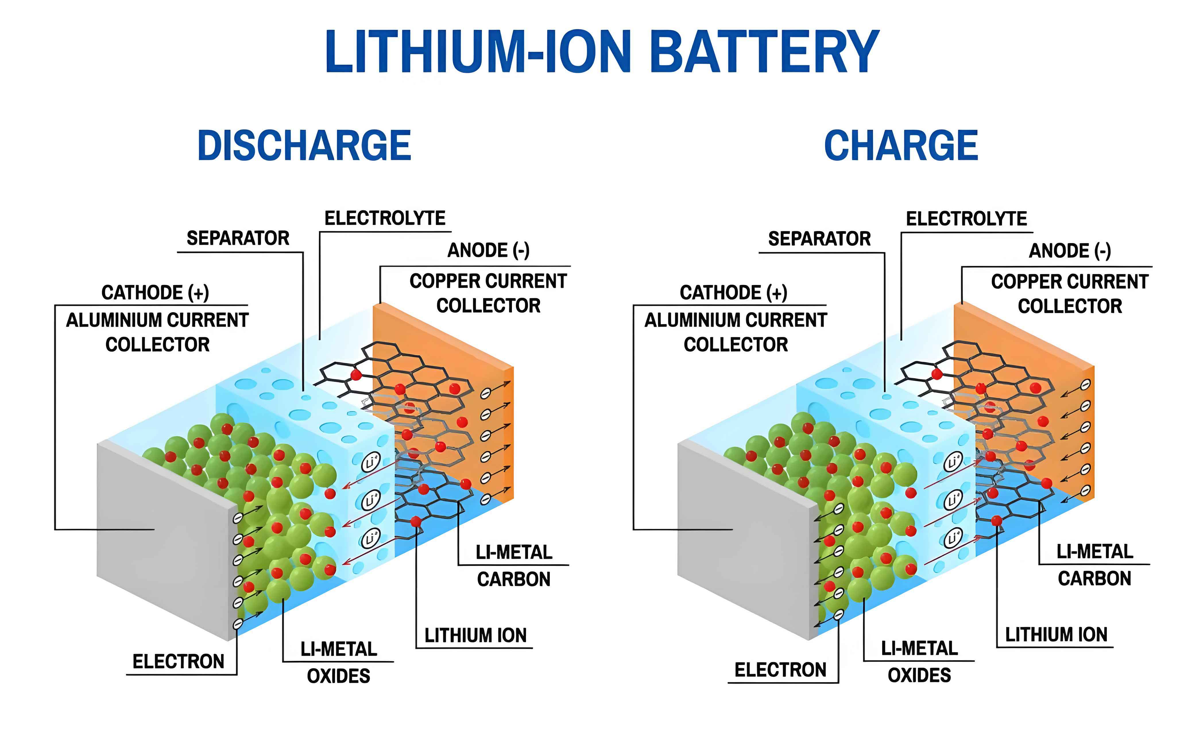
Existing equalization techniques for lithium-ion battery packs can be broadly categorized into passive and active methods. Passive equalization, also known as dissipative equalization, uses resistors to dissipate excess energy from higher-SOC cells as heat. This approach is simple, cost-effective, and widely integrated into commercial BMS chips. However, its low equalization current limits speed and efficiency, making it unsuitable for fast-charging or high-power applications. Active equalization, on the other hand, employs energy storage elements like capacitors, inductors, or transformers to transfer energy between cells or between cells and the pack. This method offers higher efficiency and faster equalization but at the cost of increased circuit complexity, size, and expense. Given that the performance distribution of lithium-ion battery cells typically follows a normal distribution—with most cells having moderate performance and only a few being outliers—relying solely on one method is suboptimal. Using only active equalization would require balancing many cells to match the best-performing ones, while using only passive equalization would necessitate balancing many cells to match the worst-performing ones. This inefficiency motivates the development of hybrid approaches.
In this research, I propose a practical active-passive equalization circuit for lithium-ion battery packs, leveraging the STM32 microcontroller for control. The passive equalization circuit handles cells with above-average performance by dissipating excess energy, while the active equalization circuit boosts the performance of below-average cells by transferring energy from the entire pack via a DC-DC converter. This hybrid strategy aligns with the normal distribution of lithium-ion battery characteristics, targeting only the minority of outlier cells for equalization, thereby improving overall efficiency and reducing complexity. The circuit design is based on the STM32F107VGT6 microcontroller and the AS6803 battery monitoring chip, which integrates voltage sensing and passive balancing drivers. The active equalization circuit uses a single DC-DC converter to charge any low-SOC cell selectively. This article provides a detailed analysis of the circuit’s working principles, design implementation, and experimental validation, demonstrating its feasibility for enhancing the consistency and longevity of lithium-ion battery packs.
The importance of effective equalization for lithium-ion battery systems cannot be overstated. As the demand for energy storage grows, optimizing the performance of every lithium-ion battery cell becomes crucial for sustainability and cost-effectiveness. This research contributes to that goal by presenting a balanced approach that combines the strengths of both passive and active methods, tailored to the statistical reality of lithium-ion battery variability.
Analysis of Equalization Circuit Working Principles
The proposed active-passive equalization circuit topology is designed for a series-connected lithium-ion battery pack. Let’s consider a pack with N cells, where each cell is denoted as Bi (i = 1, 2, …, N). The circuit comprises two main parts: a passive equalization branch and an active equalization branch for each cell. The passive branch includes a MOSFET switch Ki and a balancing resistor Ri, connected in parallel across each lithium-ion battery cell. When Ki is closed, the cell discharges through Ri, dissipating energy as heat to reduce its SOC. The active branch consists of two switches Qi and Qi+1 (or similar configuration) that connect the cell to a shared DC-DC converter. This converter draws energy from the entire pack and delivers it to the selected low-SOC lithium-ion battery cell, effectively charging it.
The core idea is to use passive equalization for cells with SOC above the pack average and active equalization for cells with SOC below the average. This is based on the assumption that the SOC distribution of lithium-ion battery cells in a pack is normal. Mathematically, if the SOC of cell i is SOCi, and the average SOC of the pack is SOCavg = (1/N) ∑i=1N SOCi, then the equalization decision can be formulated as:
- If SOCi > SOCavg + Δ, enable passive equalization for cell i.
- If SOCi < SOCavg – Δ, enable active equalization for cell i.
- Otherwise, no equalization is needed.
Here, Δ is a hysteresis threshold to prevent frequent switching. This strategy minimizes the number of cells undergoing equalization, as only those outside a defined range are adjusted. The normal distribution of lithium-ion battery performance implies that the probability density function f(SOC) is given by:
$$ f(SOC) = \frac{1}{\sigma \sqrt{2\pi}} e^{-\frac{(SOC – \mu)^2}{2\sigma^2}} $$
where μ is the mean SOC and σ is the standard deviation. The fraction of cells requiring equalization can be estimated using the cumulative distribution function. For a typical lithium-ion battery pack, σ is small, so only a small percentage of cells are outliers, justifying the hybrid approach.
The active equalization circuit operates by using a bidirectional DC-DC converter (e.g., a buck-boost converter) to transfer energy. When active equalization is needed for a specific lithium-ion battery cell, the corresponding switches are closed, connecting the cell to the converter. The converter steps down the pack voltage to the cell voltage for charging. The efficiency ηactive of this process depends on the converter design and can be modeled as:
$$ \eta_{\text{active}} = \frac{P_{\text{out}}}{P_{\text{in}}} = \frac{V_{\text{cell}} \cdot I_{\text{charge}}}{V_{\text{pack}} \cdot I_{\text{pack}}} $$
where Vcell is the cell voltage, Icharge is the charging current, Vpack is the total pack voltage, and Ipack is the current drawn from the pack. High-efficiency converters (η > 90%) are preferable to minimize energy loss. In contrast, passive equalization efficiency is inherently low, as all excess energy is dissipated as heat. The power dissipated in the resistor for cell i is:
$$ P_{\text{passive}, i} = \frac{(V_{\text{cell}, i})^2}{R_i} $$
where Ri is the balancing resistance. The equalization current Iequal, passive = Vcell, i / Ri is typically limited to a few hundred milliamps to avoid excessive heat.
The control algorithm, implemented on the STM32 microcontroller, continuously monitors the voltage of each lithium-ion battery cell using the AS6803 chip. Based on the voltage differences (which correlate with SOC), it decides which equalization method to activate. The algorithm prioritizes safety by ensuring that no cell exceeds safe voltage limits during equalization. The following table summarizes the key parameters and comparisons between passive and active equalization for lithium-ion battery packs:
| Parameter | Passive Equalization | Active Equalization | Hybrid (Proposed) |
|---|---|---|---|
| Equalization Method | Energy dissipation via resistors | Energy transfer via DC-DC converter | Combination of both |
| Efficiency | Low (0%) | High (>90%) | Moderate to High |
| Equalization Current | Small (e.g., 100 mA) | Large (e.g., 1 A) | Adaptive |
| Circuit Complexity | Low | High | Medium |
| Cost | Low | High | Medium |
| Target Cells | High-SOC lithium-ion batteries | Low-SOC lithium-ion batteries | Outlier cells only |
| Heat Generation | High | Low | Reduced |
The working principle can be further illustrated with a scenario. Suppose in a 4-cell lithium-ion battery pack, cell B1 has a higher SOC than others, and cell B3 has a lower SOC. The controller will close switch K1 to enable passive equalization for B1, causing it to discharge through R1. Simultaneously, it will close switches Q5 and Q6 (assuming a specific topology) to connect B3 to the DC-DC converter for active charging. Over time, the SOC of B1 decreases, and that of B3 increases, converging toward the pack average. This process continues until all cells are within the acceptable SOC range, ensuring balanced operation of the lithium-ion battery pack.
The mathematical model for the equalization dynamics can be described using differential equations. For a lithium-ion battery cell undergoing passive equalization, the rate of SOC change is:
$$ \frac{dSOC_i}{dt} = -\frac{I_{\text{equal, passive}}}{C_i} $$
where Ci is the capacity of cell i in ampere-hours. For active equalization, the rate is:
$$ \frac{dSOC_j}{dt} = \frac{\eta_{\text{active}} \cdot I_{\text{charge}}}{C_j} $$
By integrating these equations, the time required for equalization can be estimated, aiding in BMS design. The hybrid approach optimizes this time by using faster active equalization for critically low cells and slower passive equalization for high cells, reducing overall equalization duration compared to pure passive systems.
Circuit Design and Implementation
The hardware design of the active-passive equalization circuit centers on the STM32F107VGT6 microcontroller, chosen for its high performance, multiple peripherals, and low power consumption. This microcontroller serves as the brain of the system, executing control algorithms, processing sensor data, and managing communication. The voltage monitoring and passive equalization driver are handled by the AS6803 chip, which supports up to 12 series-connected lithium-ion battery cells. This integration simplifies the design by reducing external components. The AS6803 communicates with the STM32 via SPI or I2C, providing cell voltage data and enabling control of the passive balancing MOSFETs.
The passive equalization circuit for each lithium-ion battery cell consists of a MOSFET (e.g., NCE3401AY) and a parallel combination of resistors to achieve the desired balancing current. For instance, using three 150Ω resistors in parallel gives an effective resistance of 50Ω. Assuming a typical cell voltage of 3.7V for a lithium-ion battery, the balancing current is approximately I = V/R = 3.7/50 = 74 mA. This current is sufficient for slow equalization while minimizing heat generation. The MOSFET is driven by the AS6803’s internal drivers, which are controlled by the STM32 based on voltage readings.
The active equalization circuit is more complex. It includes a DC-DC converter that can output a stable voltage (e.g., 5V) for charging individual cells. The converter is designed as a buck converter if the pack voltage is higher than the cell voltage, which is typically the case for series-connected lithium-ion batteries. The input of the converter is connected to the entire pack, and the output is routed to each cell through a network of switches. These switches are optocouplers or solid-state relays to provide isolation and prevent cross-conduction. For a 4-cell pack, the switching network consists of pairs of switches (e.g., Q1-Q2 for cell 1, Q3-Q4 for cell 2, etc.). When active equalization is required for a specific lithium-ion battery cell, the corresponding switch pair is closed, connecting the cell to the converter output. The converter’s output voltage is set slightly above the cell’s current voltage to ensure charging, and current limiting is implemented to protect the cell.
The DC-DC converter design involves calculating component values for the buck converter. The output voltage Vout is set to 5V, and the input voltage Vin is the pack voltage, which for a 4-cell lithium-ion battery pack is around 14.8V (assuming 3.7V per cell). The duty cycle D of the buck converter is given by:
$$ D = \frac{V_{\text{out}}}{V_{\text{in}}} = \frac{5}{14.8} \approx 0.338 $$
The inductor L and capacitor C values are chosen to ensure continuous conduction mode and low output ripple. For a switching frequency fsw = 100 kHz, the inductor value can be calculated as:
$$ L = \frac{(V_{\text{in}} – V_{\text{out}}) \cdot D}{f_{\text{sw}} \cdot \Delta I_L} $$
where ΔIL is the inductor current ripple, typically set to 20-40% of the average current. For a charging current Icharge = 1A, if ΔIL = 0.3A, then:
$$ L = \frac{(14.8 – 5) \cdot 0.338}{100 \times 10^3 \cdot 0.3} \approx 110 \mu H $$
The output capacitor is selected to filter the ripple voltage ΔVout:
$$ C = \frac{\Delta I_L}{8 \cdot f_{\text{sw}} \cdot \Delta V_{\text{out}}} $$
If ΔVout = 50 mV, then C ≈ 7.5 μF. A larger capacitor (e.g., 10 μF) is used for stability. These calculations ensure efficient energy transfer to the lithium-ion battery cell during active equalization.
The control software on the STM32 is developed in C using the HAL library. It initializes the AS6803, sets up ADC for additional sensing, and implements a state machine for equalization control. The algorithm periodically reads cell voltages from the AS6803, computes the average, and identifies cells needing equalization. It then activates the appropriate MOSFETs or switches. Safety features include overvoltage and undervoltage protection, temperature monitoring, and timeout mechanisms to prevent over-equalization. Communication with external systems is facilitated via a CAN bus interface, allowing real-time data logging and remote control. The CAN circuit includes a transceiver like MCP2551 connected to the STM32’s CAN peripheral, enabling transmission of battery parameters such as voltage, current, and SOC.
To summarize the design specifications, the following table lists key components and parameters for the equalization circuit targeting a 4-cell lithium-ion battery pack:
| Component | Specification | Purpose |
|---|---|---|
| Microcontroller | STM32F107VGT6 | Control and data processing |
| Battery Monitor | AS6803 | Voltage sensing and passive balancing |
| Passive MOSFET | NCE3401AY | Switch for resistor discharge |
| Balancing Resistor | 50Ω (3×150Ω parallel) | Dissipate energy from high-SOC lithium-ion batteries |
| Active Switches | Optocouplers (e.g., TLP281) | Isolate and connect cells to DC-DC converter |
| DC-DC Converter | Buck converter, 14.8V to 5V | Transfer energy to low-SOC lithium-ion batteries |
| Inductor | 110 μH | Energy storage in converter |
| Output Capacitor | 10 μF | Filter output ripple |
| CAN Transceiver | MCP2551 | Communication interface |
| Cell Type | Lithium-ion battery, 3.7V nominal | Energy storage units |
The implementation also considers power supply design for the microcontroller and peripherals, using linear regulators or additional DC-DC converters to derive 3.3V and 5V from the pack. Overall, this design balances complexity and performance, making it suitable for practical applications involving lithium-ion battery packs in electric vehicles, energy storage systems, or portable devices.
Experimental Validation and Results
To validate the proposed active-passive equalization circuit, I constructed a prototype for a 4-cell lithium-ion battery pack using 18650 cells with nominal capacities of 2600 mAh each. The cells were initially conditioned to different SOC levels to simulate imbalances: Cell 1 at 80% SOC, Cell 2 at 75%, Cell 3 at 70%, and Cell 4 at 85%. The experiment aimed to demonstrate that the hybrid circuit could bring all cells to a similar SOC efficiently. The setup included the STM32-based controller, the AS6803 board, the DC-DC converter, and load resistors for discharge testing. Data was collected via the CAN bus and logged on a PC for analysis.
The first test focused on passive equalization. With Cell 4 having the highest voltage, the controller enabled its passive balancing MOSFET. The voltage trend over time was recorded. The balancing current was measured at approximately 74 mA, consistent with design calculations. Over a period of 5000 seconds, Cell 4’s voltage decreased from 4.15V to 4.05V, while the other cells remained stable, showing successful equalization. The energy dissipated during this process can be calculated as:
$$ E_{\text{dissipated}} = \int_0^T P_{\text{passive}} \, dt = \int_0^{5000} \frac{V(t)^2}{R} \, dt $$
Assuming an average voltage of 4.1V, E ≈ (4.12/50) * 5000 ≈ 1681 J. This heat loss is acceptable for occasional equalization but underscores the inefficiency of passive methods for large imbalances in lithium-ion battery packs.
The second test evaluated active equalization. Here, Cell 1 was artificially discharged to a lower voltage (3.2V) to represent a weak lithium-ion battery cell. The controller activated the active equalization circuit, closing the switches to connect Cell 1 to the DC-DC converter. The converter provided a charging current of 1A at 5V output. Over 800 seconds, Cell 1’s voltage rose to 3.6V, approaching the pack average. The efficiency of the active equalization was measured by comparing input and output power. The input power from the pack was Pin = Vpack * Ipack = 14.8V * 0.35A ≈ 5.18W, and the output power to the cell was Pout = Vcell * Icharge ≈ 3.4V * 1A = 3.4W (averaged). Thus, the efficiency η ≈ 3.4/5.18 ≈ 65.6%, which is lower than expected due to converter losses and switch resistances. Optimizing the converter design could improve this, but the result still demonstrates effective energy transfer to the lithium-ion battery cell.
A combined test was conducted where both passive and active equalization were used simultaneously. Initially, Cell 4 had high SOC (4.15V) and Cell 3 had low SOC (3.25V). The controller enabled passive equalization for Cell 4 and active equalization for Cell 3. The following table summarizes the voltage changes over time, illustrating the convergence:
| Time (s) | Cell 1 Voltage (V) | Cell 2 Voltage (V) | Cell 3 Voltage (V) | Cell 4 Voltage (V) | Actions |
|---|---|---|---|---|---|
| 0 | 3.70 | 3.68 | 3.25 | 4.15 | Start |
| 1000 | 3.70 | 3.68 | 3.45 | 4.10 | Active on Cell 3, Passive on Cell 4 |
| 2000 | 3.70 | 3.68 | 3.60 | 4.05 | Continuing |
| 3000 | 3.70 | 3.68 | 3.68 | 4.00 | Near balance |
| 4000 | 3.70 | 3.68 | 3.69 | 3.98 | Equalization stopped |
The data shows that after 4000 seconds, all lithium-ion battery cells were within 0.02V of each other, indicating successful balancing. The hybrid approach reduced the total equalization time compared to using only passive methods, which would have taken longer to raise Cell 3’s voltage. The energy efficiency of the hybrid system can be analyzed by considering the total energy used. For passive equalization, energy is wasted as heat, while for active equalization, most energy is transferred usefully. The overall system efficiency for the combined operation depends on the proportion of cells undergoing each type. Since only outlier cells are targeted, the hybrid system minimizes energy loss, making it suitable for lithium-ion battery packs where efficiency is critical.
To further quantify performance, I calculated the equalization speed metric, defined as the rate of SOC change per cell. For passive equalization of Cell 4, with capacity C = 2.6 Ah and current I = 0.074 A, the speed is:
$$ \text{Speed}_{\text{passive}} = \frac{I}{C} = \frac{0.074}{2.6} \approx 0.0285 \, \text{h}^{-1} $$
For active equalization of Cell 3, with I = 1 A, the speed is:
$$ \text{Speed}_{\text{active}} = \frac{1}{2.6} \approx 0.3846 \, \text{h}^{-1} $$
Thus, active equalization is about 13.5 times faster than passive in this setup, highlighting its advantage for critical imbalances in lithium-ion batteries. However, the hybrid approach wisely applies fast active equalization only where needed, conserving energy and reducing heat generation.
The experiments also included stress tests under varying load conditions. A constant current load of 2A was applied to the pack while equalization was active. The circuit maintained stable operation, with the STM32 adjusting equalization currents based on real-time voltage readings. Temperature measurements on the balancing resistors and DC-DC converter showed rises within safe limits (below 60°C), confirming thermal manageability. The CAN communication successfully transmitted data packets containing cell voltages, equalization status, and error flags, enabling remote monitoring.
In summary, the experimental results validate the feasibility of the STM32-based active-passive equalization circuit for lithium-ion battery packs. The hybrid strategy effectively balances cells with minimal energy waste and reasonable speed, addressing the limitations of pure passive or active systems. The use of commercial components like the AS6803 and STM32 ensures reliability and scalability for larger packs, making this design a practical solution for enhancing the performance and lifespan of lithium-ion battery systems.
Conclusion and Future Work
This research presents a hybrid active-passive equalization circuit for lithium-ion battery packs, controlled by an STM32 microcontroller. The circuit leverages the normal distribution of lithium-ion battery performance, applying passive equalization to high-SOC cells and active equalization to low-SOC cells, thereby targeting only outlier cells for balancing. This approach reduces the number of cells undergoing equalization, improves overall efficiency, and lowers complexity compared to pure active or passive systems. The design details, including the use of the AS6803 for voltage monitoring and a custom DC-DC converter for energy transfer, are elaborated, along with mathematical models for equalization dynamics.
Experimental validation on a 4-cell lithium-ion battery pack demonstrates that the circuit successfully converges cell voltages within a small range, with passive equalization handling minor imbalances and active equalization addressing significant deficits. The results show that the hybrid method offers a balanced trade-off between speed, efficiency, and cost, making it suitable for real-world applications like electric vehicles and energy storage systems. The integration of CAN communication facilitates system integration and data analysis, enhancing the BMS’s functionality.
Future work could focus on several improvements. First, the active equalization efficiency could be boosted by using more advanced DC-DC topologies, such as resonant converters, to reduce switching losses. Second, the control algorithm could incorporate SOC estimation based on coulomb counting or Kalman filtering, rather than just voltage, for more accurate balancing of lithium-ion battery cells. Third, the circuit could be scaled to higher-voltage packs (e.g., 48V or 400V) for automotive use, requiring careful isolation and component selection. Fourth, machine learning techniques could be applied to predict cell aging and optimize equalization schedules, prolonging the lifespan of lithium-ion battery packs. Finally, cost reduction through integration of the entire system into a single ASIC could make the technology more accessible for mass production.
In conclusion, the active-passive equalization circuit represents a step forward in BMS technology, addressing the inherent inconsistencies in lithium-ion battery packs with a pragmatic hybrid approach. As the world transitions to renewable energy and electrified transportation, such innovations will play a crucial role in maximizing the utility and sustainability of lithium-ion batteries, contributing to a greener future.