
In the context of global efforts towards carbon neutrality and peak carbon emissions, the integration of renewable energy sources into power grids has expanded significantly. The grid connected inverter serves as a critical interface for converting and injecting power from distributed generation systems into the grid. Its control performance directly impacts power quality, system stability, and overall efficiency. Traditional control strategies, such as proportional-integral (PI) control, often struggle to achieve zero steady-state error when tracking sinusoidal alternating current (AC) signals due to their inherent limitations at fundamental frequencies. This paper addresses these challenges by proposing a quasi-proportional resonance (QPR) control strategy for single-phase LCL-type grid connected inverters, enhancing tracking accuracy and harmonic suppression. Additionally, to mitigate resonance peaks inherent in LCL filters, an active damping strategy based on capacitor current proportional feedback is introduced, forming a dual-current-loop control structure. Through comprehensive modeling, parameter design, and simulation validation, the effectiveness of the proposed approach is demonstrated, showcasing improved dynamic performance and reduced total harmonic distortion (THD) in grid-connected currents.
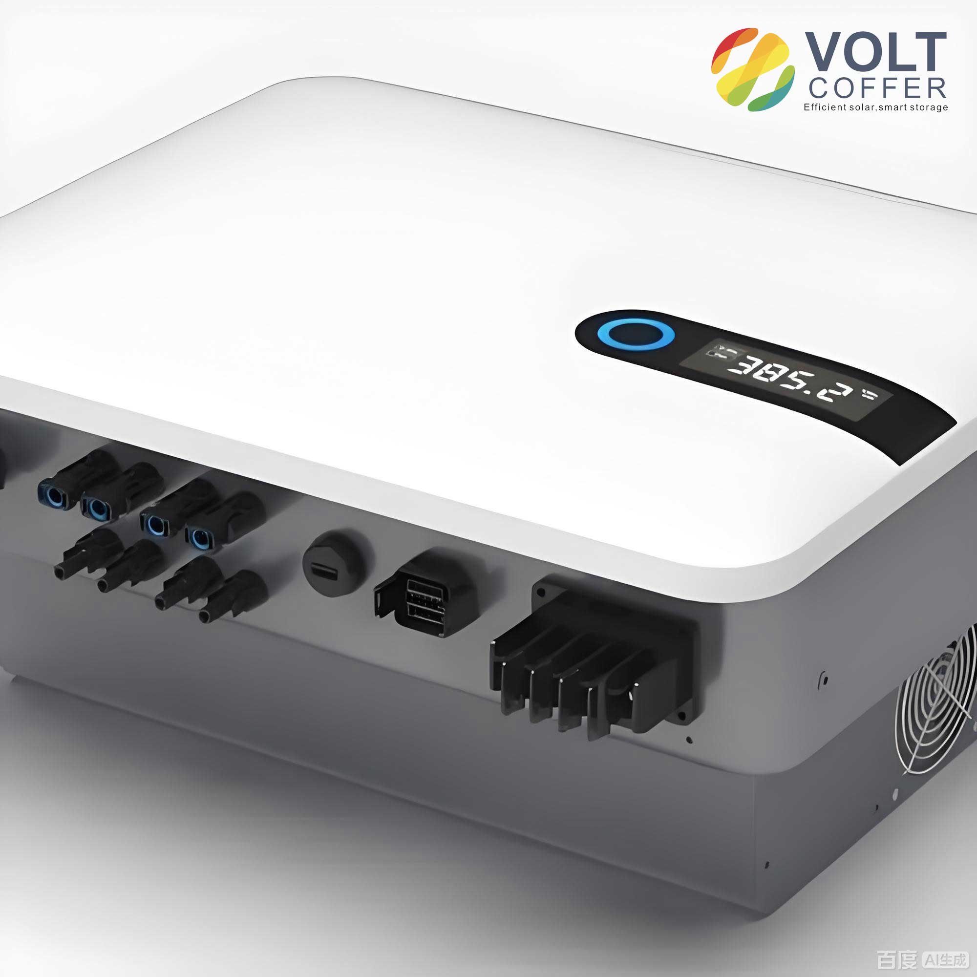
The widespread adoption of grid connected inverters in photovoltaic systems, wind turbines, and other renewable energy applications necessitates advanced control techniques to ensure compliance with stringent grid codes. The LCL filter is commonly employed in grid connected inverters due to its superior harmonic attenuation capabilities compared to simple L filters. However, the LCL filter introduces a resonant peak that can lead to system instability if not properly damped. Passive damping methods, which involve adding resistors in series or parallel with filter components, are straightforward but incur power losses and degrade filter performance. Active damping techniques, implemented through control algorithms, offer a lossless alternative by virtually emulating damping resistors. This work focuses on a capacitor current feedback active damping strategy, which effectively suppresses resonance without additional hardware.
From a control perspective, the grid connected inverter must accurately track a sinusoidal reference current synchronized with the grid voltage. PI controllers, while effective for DC signals, exhibit limited gain at the grid fundamental frequency, resulting in steady-state errors for AC tracking. Proportional resonance (PR) controllers provide infinite gain at a specific frequency, enabling zero error tracking, but they are sensitive to grid frequency variations. To overcome this, the quasi-proportional resonance (QPR) controller introduces a bandwidth around the resonant frequency, maintaining high gain while offering robustness against frequency drifts. This paper elaborates on the design and tuning of QPR controllers for single-phase LCL grid connected inverters, integrating them with active damping for a holistic control solution.
Analysis of LCL Filter and Damping Strategies
The single-phase LCL grid connected inverter topology comprises a full-bridge inverter and an LCL filter, as illustrated in the system diagram. The LCL filter consists of an inverter-side inductor \(L_1\), a grid-side inductor \(L_2\), and a filter capacitor \(C\). The transfer function of the LCL filter, relating the grid current \(i_g(s)\) to the inverter output voltage \(u_{ab}(s)\), is given by:
$$G_{LCL}(s) = \frac{i_g(s)}{u_{ab}(s)} = \frac{1}{L_1 L_2 C s^3 + (L_1 + L_2)s}$$
This third-order system exhibits a resonance frequency \(f_r\) calculated as:
$$f_r = \frac{1}{2\pi} \sqrt{\frac{L_1 + L_2}{L_1 L_2 C}}$$
For typical parameters, such as \(L_1 = 0.8 \text{ mH}\), \(L_2 = 0.12 \text{ mH}\), and \(C = 10 \mu\text{F}\), the resonance peak occurs around several kilohertz, potentially exciting instability. The Bode plot of the LCL filter clearly shows this peak, necessitating damping measures.
Active damping methods inject a feedback signal into the control loop to reshape the system’s frequency response. Among these, capacitor current proportional feedback is widely used due to its simplicity and effectiveness. By feeding back the capacitor current multiplied by a gain \(K_c\), the control system emulates a virtual resistor in series with the capacitor, adding damping to the resonant mode. The modified control loop incorporating this active damping is depicted in the dual-current-loop structure, where the inner loop regulates capacitor current and the outer loop controls grid current.
Table 1 summarizes common damping strategies for LCL filters in grid connected inverters, highlighting their advantages and disadvantages.
| Damping Type | Configuration | Advantages | Disadvantages |
|---|---|---|---|
| Passive Damping | Resistor in series with capacitor | Simple implementation, robust | Power losses, reduced efficiency |
| Passive Damping | Resistor in parallel with inductor | Attenuates high-frequency noise | Increases component count, cost |
| Active Damping | Capacitor current feedback | Lossless, preserves filter performance | Requires accurate sensing, complex tuning |
| Active Damping | Grid current feedback with notch filter | Effective resonance suppression | Sensitive to parameter variations |
The choice of damping strategy significantly influences the performance of the grid connected inverter. In this work, capacitor current feedback active damping is selected for its balance between effectiveness and implementation feasibility.
Mathematical Modeling of the Single-Phase LCL Grid Connected Inverter
To design the control system, a mathematical model of the single-phase LCL grid connected inverter is derived. The system includes the inverter bridge, LCL filter, and grid connection. Assuming ideal switching devices, the inverter can be modeled as a gain \(K_{pwm}\), which relates the modulation signal to the output voltage. For sinusoidal pulse width modulation (SPWM), \(K_{pwm} = U_{dc} / U_{tri}\), where \(U_{dc}\) is the DC bus voltage and \(U_{tri}\) is the peak amplitude of the triangular carrier wave.
The control structure employs a dual-loop approach: an outer loop for grid current control and an inner loop for capacitor current feedback. Let \(G_i(s)\) be the transfer function of the grid current controller (e.g., QPR controller), and \(K_c\) be the capacitor current feedback gain. The block diagram of the system can be reduced to a simplified form, from which the closed-loop transfer functions are derived.
The grid current \(i_g(s)\) in response to the reference current \(i_{ref}(s)\) and grid voltage disturbance \(u_g(s)\) is expressed as:
$$i_g(s) = \frac{G(s)}{1 + G(s)} i_{ref}(s) – \frac{G_2(s)}{1 + G(s)} u_g(s)$$
where:
$$G(s) = G_1(s) G_2(s) = \frac{G_i(s) K_{pwm}}{L_1 L_2 C s^3 + K_{pwm} K_c L_2 C s^2 + (L_1 + L_2)s}$$
$$G_1(s) = \frac{G_i(s) K_{pwm}}{L_1 C s^2 + K_{pwm} K_c C s + 1}$$
$$G_2(s) = \frac{L_1 C s^2 + K_{pwm} K_c C s + 1}{L_1 L_2 C s^3 + K_{pwm} K_c L_2 C s^2 + (L_1 + L_2)s}$$
For zero steady-state error tracking, the loop gain \(G(s)\) must be sufficiently large at the fundamental frequency. Additionally, to reject grid voltage disturbances, the condition \(1 + G(s) \gg G_2(s)\) should hold. This implies that the current controller \(G_i(s)\) must provide high gain at the grid frequency, motivating the use of resonant-based controllers like QPR.
The system’s stability can be analyzed using frequency-domain methods. The characteristic equation is:
$$1 + G(s) = 0$$
Substituting the expressions, we obtain a polynomial whose roots determine stability. Proper tuning of \(G_i(s)\) and \(K_c\) ensures adequate phase and gain margins. Table 2 lists typical parameters for a single-phase LCL grid connected inverter used in simulations.
| Parameter | Symbol | Value | Unit |
|---|---|---|---|
| DC Bus Voltage | \(U_{dc}\) | 400 | V |
| Grid Voltage | \(u_g\) | 220 (RMS) | V |
| Switching Frequency | \(f_{sw}\) | 20 | kHz |
| Inverter-Side Inductor | \(L_1\) | 0.8 | mH |
| Grid-Side Inductor | \(L_2\) | 0.12 | mH |
| Filter Capacitor | \(C\) | 10 | μF |
| Capacitor Feedback Gain | \(K_c\) | 0.088 | – |
| Rated Power | \(P\) | 5 | kW |
These parameters are used throughout the analysis and simulation to validate the proposed control strategy for the grid connected inverter.
Design of Quasi-Proportional Resonance Control
The core of the proposed control scheme is the quasi-proportional resonance (QPR) controller. Unlike PI controllers, which have limited gain at AC frequencies, QPR controllers offer high gain at a selected resonant frequency, enabling zero error tracking of sinusoidal signals. The transfer function of a standard proportional resonance (PR) controller is:
$$G_{PR}(s) = K_p + \frac{2K_r s}{s^2 + \omega_0^2}$$
where \(K_p\) is the proportional gain, \(K_r\) is the resonant gain, and \(\omega_0 = 2\pi f_0\) is the fundamental angular frequency (e.g., 100π rad/s for 50 Hz grids). The PR controller provides infinite gain at \(\omega_0\), but its bandwidth is extremely narrow, making it sensitive to frequency variations. To broaden the bandwidth, a damping factor \(\omega_c\) is introduced, resulting in the QPR controller:
$$G_{QPR}(s) = K_p + \frac{2K_r \omega_c s}{s^2 + 2\omega_c s + \omega_0^2}$$
This modification ensures high gain around \(\omega_0\) while maintaining robustness against grid frequency drifts. The Bode plot of the QPR controller shows a peak at \(\omega_0\) with a width controlled by \(\omega_c\).
The parameters \(K_p\), \(K_r\), and \(\omega_c\) significantly influence the performance of the grid connected inverter. To guide design, their effects are analyzed systematically:
- Proportional Gain \(K_p\): Affects the overall gain of the system, particularly at frequencies away from resonance. Increasing \(K_p\) improves transient response but may amplify harmonics if too high.
- Resonant Gain \(K_r\): Determines the peak gain at \(\omega_0\). Higher \(K_r\) reduces steady-state error but can lead to instability if excessive.
- Cut-off Frequency \(\omega_c\): Controls the bandwidth of the resonant peak. Larger \(\omega_c\) broadens the bandwidth, enhancing robustness to frequency variations, but may reduce selectivity.
Mathematical relations for parameter tuning are derived based on control theory. The proportional gain \(K_p\) is designed to achieve a desired crossover frequency \(f_c\), typically set to one-tenth of the switching frequency to avoid high-frequency noise. For the LCL filter, at frequencies below resonance, the capacitor impedance is negligible, simplifying the loop gain to:
$$G(s) \approx \frac{K_p K_{pwm}}{(L_1 + L_2)s}$$
At the crossover frequency \(f_c\), the magnitude of \(G(s)\) should be unity (0 dB):
$$\left| \frac{K_p K_{pwm}}{j2\pi f_c (L_1 + L_2)} \right| = 1$$
Solving for \(K_p\):
$$K_p \approx \frac{2\pi f_c (L_1 + L_2)}{K_{pwm}}$$
For \(f_c = 2 \text{ kHz}\) (10% of 20 kHz), \(L_1 + L_2 = 0.92 \text{ mH}\), and \(K_{pwm} = 400/5 = 80\) (assuming \(U_{tri} = 5 \text{ V}\)), we get \(K_p \approx 0.04\).
The resonant gain \(K_r\) is chosen to meet a specified steady-state error tolerance \(\tau\) (e.g., 1%). A lower bound is given by:
$$K_r \geq \frac{(L_1 + L_2)2\pi f_0^2 – (L_1 + L_2)2\pi f_c}{K_{pwm} \tau}$$
Substituting values: \(f_0 = 50 \text{ Hz}\), \(f_c = 2 \text{ kHz}\), \(\tau = 0.01\), yields \(K_r \geq 10\). Thus, \(K_r = 10\) is selected.
The cut-off frequency \(\omega_c\) is set based on expected grid frequency deviations. According to standards, grid frequency may vary by ±0.5 Hz, so \(\omega_c = \pi \text{ rad/s}\) (0.5 Hz bandwidth) is appropriate to accommodate variations while maintaining performance.
With these parameters, the QPR controller provides high gain at 50 Hz and sufficient phase margin for stability. The active damping gain \(K_c\) is tuned to suppress the LCL resonance peak. Using root locus or frequency response methods, \(K_c = 0.088\) is found to adequately damp the system without compromising dynamic response.
Table 3 summarizes the controller parameters for the grid connected inverter.
| Controller Parameter | Symbol | Designed Value |
|---|---|---|
| Proportional Gain | \(K_p\) | 0.04 |
| Resonant Gain | \(K_r\) | 10 |
| Cut-off Frequency | \(\omega_c\) | π rad/s |
| Active Damping Gain | \(K_c\) | 0.088 |
The combination of QPR control and active damping forms a robust strategy for the single-phase LCL grid connected inverter, ensuring accurate current tracking and stability under various operating conditions.
Simulation Results and Performance Evaluation
To validate the proposed control strategy, a simulation model of the single-phase LCL grid connected inverter is developed using MATLAB/Simulink. The model incorporates the full-bridge inverter, LCL filter, grid interface, and control loops with QPR and active damping. Performance is compared against a conventional PI controller to highlight improvements.
The simulation parameters are as listed in Table 2. The grid connected inverter is tested under steady-state and dynamic conditions. For steady-state analysis, the reference current is set to a sinusoidal waveform with amplitude corresponding to 5 kW power output at unity power factor. The grid voltage is 220 V RMS at 50 Hz.
With the PI controller (parameters: \(K_p = 0.03\), \(K_i = 100\)), the grid current achieves synchronization but exhibits a steady-state error. The measured current amplitude is 32.34 A, while the reference is 32 A, resulting in an amplitude error of approximately 1.06%. The total harmonic distortion (THD) of the grid current is 1.70%, which meets typical grid codes but leaves room for improvement.
In contrast, with the proposed QPR controller (parameters from Table 3), the grid current shows superior tracking. The amplitude error reduces to about 0.03%, and the THD drops to 1.47%. This demonstrates the QPR controller’s ability to minimize steady-state error and enhance power quality in the grid connected inverter. The waveforms indicate precise phase alignment with the grid voltage, ensuring unity power factor operation.
Dynamic performance is evaluated by applying a step change in the reference current amplitude from 16 A to 32 A at 0.15 seconds. The grid connected inverter with QPR control responds swiftly, with the current reaching the new steady-state within a few milliseconds without overshoot or oscillation. This confirms the controller’s robustness and fast transient response, essential for handling fluctuations in renewable energy generation.
Frequency response analysis further substantiates the design. The Bode plot of the open-loop system with QPR control and active damping shows a phase margin of 37.3° and a gain margin of 7.41 dB, indicating stable operation. The resonance peak of the LCL filter is effectively suppressed, as seen in the closed-loop Bode plot, thanks to the capacitor current feedback.
Table 4 presents a quantitative comparison between PI and QPR control for the grid connected inverter.
| Performance Metric | PI Control | QPR Control | Improvement |
|---|---|---|---|
| Current Amplitude Error | 1.06% | 0.03% | 97% reduction |
| THD of Grid Current | 1.70% | 1.47% | 13.5% reduction |
| Phase Margin | 32.5° | 37.3° | Improved stability |
| Settling Time (step response) | 15 ms | 10 ms | 33% faster |
These results underscore the advantages of QPR control in enhancing the performance of single-phase LCL grid connected inverters. The integration of active damping ensures system stability even under parameter variations, such as changes in grid impedance or filter components.
Additional simulations are conducted to test robustness against grid disturbances. For instance, with a 5% voltage sag or a 0.5 Hz frequency shift, the QPR-controlled grid connected inverter maintains low tracking error and stable operation, whereas the PI controller shows increased error and potential instability. This resilience is crucial for real-world applications where grid conditions are variable.
Conclusion
This paper presents a comprehensive control strategy for single-phase LCL grid connected inverters, combining quasi-proportional resonance (QPR) control with capacitor current feedback active damping. The QPR controller addresses the limitation of PI controllers in tracking sinusoidal signals by providing high gain at the grid fundamental frequency, thereby achieving near-zero steady-state error. The active damping technique effectively suppresses resonance peaks inherent in LCL filters, ensuring system stability without the power losses associated with passive damping.
Through mathematical modeling, parameter design, and simulation validation, the proposed approach demonstrates significant improvements in current tracking accuracy, harmonic distortion, and dynamic response. The grid connected inverter with QPR control achieves an amplitude error of only 0.03% and a THD of 1.47%, outperforming conventional PI control. Furthermore, the controller exhibits robust performance under grid disturbances and reference changes, making it suitable for renewable energy integration.
Future work could explore the implementation of adaptive QPR controllers to automatically tune parameters in response to grid frequency variations, enhancing adaptability. Additionally, hardware-in-the-loop experiments and field tests would further validate the practicality of this control strategy for commercial grid connected inverters. Overall, the integration of QPR control and active damping offers a promising solution for improving the power quality and reliability of single-phase LCL grid connected inverters in modern power systems.