
The evolution of modern power systems, characterized by the deep integration of renewable energy sources and novel storage technologies, demands a paradigm shift in the control of grid-connected inverters. These power electronic interfaces are no longer mere power followers; they are expected to act as intelligent grid assets, providing robust power dispatch and dynamic grid support under increasingly complex and variable network conditions. Traditional control philosophies often struggle to meet these multifaceted requirements, creating a pressing need for unified, adaptive, and simplified control strategies.
The prevailing control strategies for grid connected inverters are broadly categorized by their synchronization mechanism. Grid-Following Control (GFLC), the conventional approach, relies on a Phase-Locked Loop (PLL) to synchronize with the grid voltage. While effective in stiff grids, its performance degrades in weak grids, suffering from power transfer limitations and potential instability. Furthermore, it inherently lacks black-start and islanding operation capabilities. Conversely, Grid-Forming Control (GFMC) generates an internal voltage reference, emulating the behavior of a synchronous generator. Techniques like droop control and Virtual Synchronous Generator (VSG) control fall under this category, offering inherent grid-support functions. However, they can face stability challenges when connected to very strong grids. This dichotomy means that a single-mode controller is not universally optimal across the wide spectrum of grid strengths encountered in practice.
Attempts to bridge this gap have led to dual-mode strategies involving switching, blending, or unifying GFLC and GFMC. These solutions, however, often introduce complexity, requiring real-time grid impedance estimation and sophisticated transition logic, which can compromise reliability. A promising alternative lies in Virtual Oscillator Control (VOC). By emulating the self-synchronizing dynamics of a nonlinear oscillator, VOC can achieve seamless synchronization without a PLL. Advanced forms, like dispatchable VOC (dVOC), incorporate power regulation, extending its applicability to grid-connected scenarios. VOC exhibits favorable dynamic performance and inherent droop-like behavior. Yet, its practical adoption is sometimes hindered by the complexity of tuning the multiple parameters associated with the underlying nonlinear oscillator model.
This article addresses these challenges by proposing a novel Oscillator-Resembled, PLL-less Unified Power and Voltage Controller (OR-PLL-less UPVC) for three-phase grid connected inverters. The core innovation is a simplified “oscillator-resembled” structure based on an enhanced Proportional-Resonant (PR) controller, which captures the essential voltage-forming dynamics of VOC while significantly reducing parameter design complexity. The proposed controller seamlessly unifies power tracking and voltage support functions, enabling a single control structure to adaptively operate as a grid-follower in strong grids and exhibit grid-forming characteristics in weak grids, all without the need for a PLL or mode-switching logic.
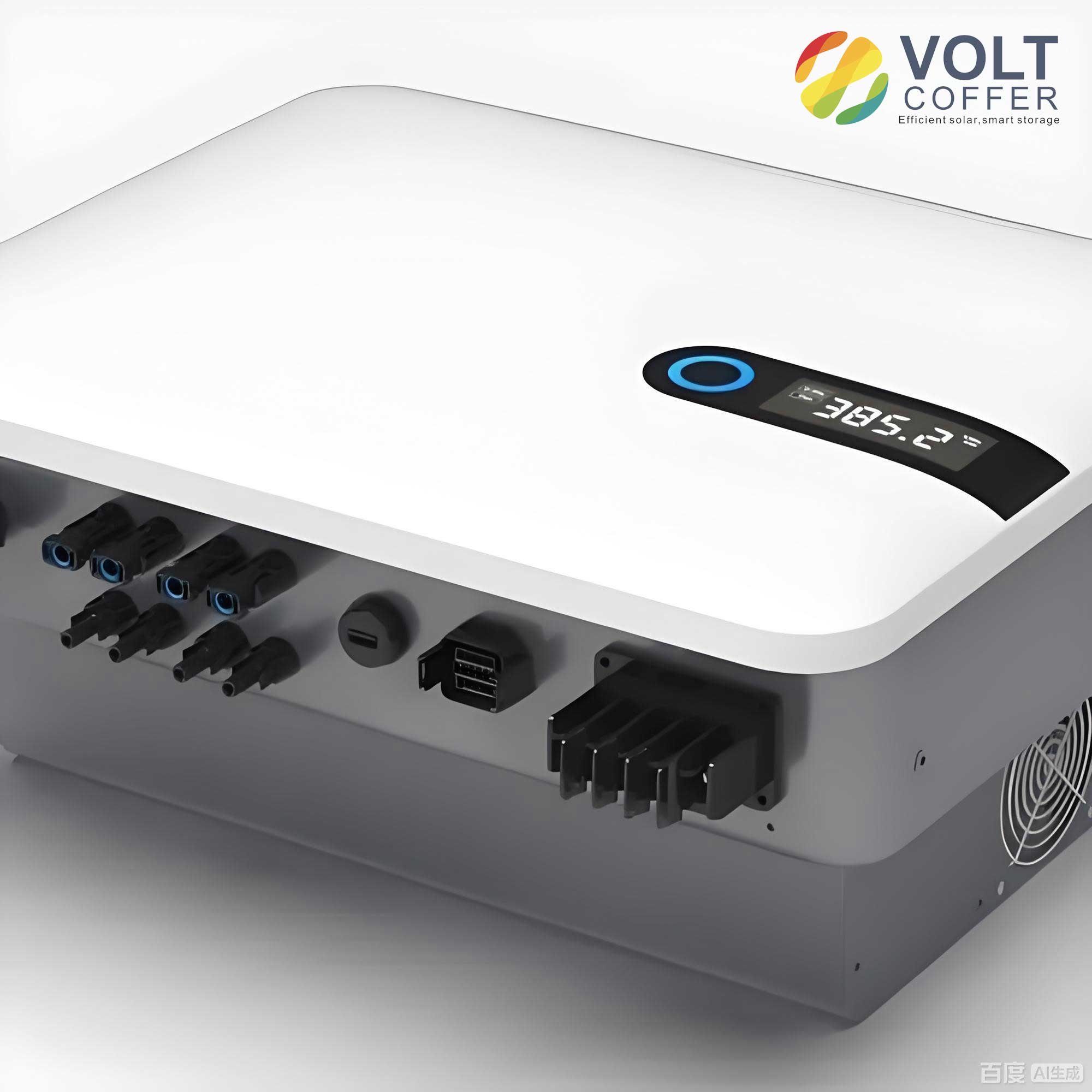
System Configuration and Controller Architecture
The considered system for the grid connected inverter is based on a standard three-phase, two-level Voltage-Sourced Converter (VSC) with an LCL output filter. The electrical topology, as illustrated, consists of a DC voltage source (Vdc), the inverter bridge, an LCL filter (with inductors L1, L2 and capacitor C), and the grid interface. The grid is represented by a Thevenin equivalent comprising an ideal voltage source vg in series with a grid impedance Zg, whose magnitude characterizes the grid’s strength (Short-Circuit Ratio, SCR). The Point of Common Coupling (PCC) is the interface where local loads may be connected and where the inverter interacts with the grid.
The proposed OR-PLL-less UPVC is architected around three core functional modules that work in concert: the Power Control (PC) module, the Voltage Self-Formation (VSF) module, and the Voltage Magnitude Regulation (VMR) module. This integrated structure replaces the conventional cascade of current loops, voltage loops, and PLLs.
The key parameters for a typical 6.6 kVA grid connected inverter system are summarized in Table 1.
| Parameter | Symbol | Value |
|---|---|---|
| DC-Link Voltage | 2Vdc | 650 V |
| Inverter-side Inductor | L1 | 5.0 mH |
| Grid-side Inductor | L2 | 4.2 mH |
| Filter Capacitor | C | 4.7 µF |
| Grid Voltage (RMS, line-line) | vg | 380 V |
| Nominal Grid Frequency | f0 | 50 Hz |
| Switching Frequency | fsw | 10 kHz |
| Rated Apparent Power | Srated | 6.6 kVA |
Principle and Design of the OR-PLL-less UPVC
1. Power Control (PC) Module
The PC module is responsible for generating the reference current that will achieve the desired active (P*) and reactive (Q*) power dispatch. Unlike traditional GFLC, the proposed controller does not use a measured PCC voltage from a PLL. Instead, it utilizes internal signals from the VSF module. The fundamental relationship is that the VSF outputs, denoted as the vector e and its orthogonal counterpart ê, provide an estimate of the PCC voltage vpcc. Specifically, in the stationary (αβ) reference frame, the relationship is designed to be:
$$ \hat{e}_{\beta} = V_{dc} e_{\alpha} \approx v_{pcc\alpha}, \quad \hat{e}_{\alpha} = -V_{dc} e_{\beta} \approx -v_{pcc\beta} $$
Based on instantaneous power theory, the αβ-axis reference currents irefα and irefβ are computed as:
$$ i_{ref\alpha} = \frac{2}{3} \left( \frac{P^* \hat{e}_{\beta}}{V_{dc}(e_{\beta}\hat{e}_{\alpha} – e_{\alpha}\hat{e}_{\beta})} + \frac{Q^* \hat{e}_{\alpha}}{V_{dc}(e_{\beta}\hat{e}_{\alpha} – e_{\alpha}\hat{e}_{\beta})} \right) $$
$$ i_{ref\beta} = \frac{2}{3} \left( \frac{P^* \hat{e}_{\alpha}}{V_{dc}(e_{\beta}\hat{e}_{\alpha} – e_{\alpha}\hat{e}_{\beta})} – \frac{Q^* \hat{e}_{\beta}}{V_{dc}(e_{\beta}\hat{e}_{\alpha} – e_{\alpha}\hat{e}_{\beta})} \right) $$
This calculation allows the grid connected inverter to track power setpoints without directly measuring the synchronized PCC voltage angle.
2. Voltage Self-Formation (VSF) Module: The “Oscillator-Resembled” Core
The VSF module is the cornerstone of the proposed unified control. Its primary function is to autonomously generate the inverter’s modulating voltage signal vm based on the current error, effectively creating a “current-error to voltage” oscillation mechanism. It is built around a modified Proportional-Resonant (PR) controller.
The transfer function of a standard PR controller is:
$$ G_{PR}(s) = k_p \left( 1 + \frac{k_r s}{s^2 + \omega_0^2} \right) $$
where kp is the proportional gain, kr is the resonant gain, and ω0 is the nominal angular frequency (e.g., 100π rad/s). In the proposed VSF, the resonant path is enhanced with a vector scaling coefficient ks. The dynamics in the αβ-frame for one axis are described by:
$$ \dot{e}_{\alpha} = k_p k_r \Delta i_{e\alpha} – \frac{1}{k_s} \hat{e}_{\alpha} $$
$$ \dot{\hat{e}}_{\alpha} = \omega_0^2 e_{\alpha} $$
and identically for the β-axis. The current error Δie is the difference between the PC module’s reference current iref and the measured inverter-side current i1 (Δie = iref – i1). The modulating voltage for the inverter bridge is then vm = Vdc e.
Synchronization Principle: The key to PLL-less operation lies in the designed relationship between e, ê, and vpcc. With proper tuning of ks (typically ks = Vdc/ω0), the vector ê becomes proportional and phase-aligned with the fundamental component of the PCC voltage vpcc. This allows the internal states of the VSF to effectively “observe” the grid voltage, enabling synchronization without a dedicated PLL. The stability of this synchronization is inherent to the oscillator-resembled dynamics.
Inherent Power-Voltage Droop Characteristics: Analyzing the dynamics of the output voltage space vector vo (closely related to vm) reveals the unified control law. The derivative of the output voltage space vector can be expressed as:
$$ \frac{d}{dt} \mathbf{v}_o = V_{dc} \left( k_p k_r \Delta \mathbf{i}_e + j \frac{1}{k_s} \mathbf{v}_o \right) $$
By expressing the current error vector in terms of active and reactive power errors (ΔP = P* – P, ΔQ = Q* – Q) and the output voltage, i.e., $$ \Delta \mathbf{i}_e \approx \frac{2}{3V_P^2} (\Delta P – j\Delta Q) \mathbf{v}_o $$, and equating it to the general form of a rotating vector derivative, we derive the fundamental control laws governing the grid connected inverter:
$$ \frac{d}{dt} V_P = V_{dc} k_p k_r \frac{2}{3V_P} \Delta P $$
$$ \omega = \omega_0 – V_{dc} k_p k_r \frac{2}{3V_P^2} \Delta Q $$
where VP and ω are the instantaneous amplitude and frequency of the inverter output voltage. These equations show that the amplitude VP has a first-order dynamic relationship with active power error (acting like a power-based voltage form), and the frequency ω exhibits a droop relationship with reactive power error. This mimics the behavior of a dispatchable virtual oscillator, providing inherent grid-support functionality.
3. Voltage Magnitude Regulation (VMR) Module
While the VSF module provides inherent droop, the final steady-state voltage amplitude is not directly set. The VMR module introduces a corrective action to regulate the voltage magnitude towards a desired reference VP*, enhancing the voltage support capability of the grid connected inverter. It generates a correction signal Δvo based on the difference between the estimated voltage magnitude |ê| and VP*:
$$ \Delta \mathbf{v}_o = k_v (|\hat{\mathbf{e}}| – V_P^*) \mathbf{e} $$
where kv is a voltage regulation coefficient. This signal is subtracted from the input of the integrators in the VSF module. Incorporating this feedback modifies the amplitude dynamics to:
$$ \frac{d}{dt} V_P = V_{dc} k_p k_r \frac{2}{3V_P} \Delta P – k_v (|\hat{\mathbf{e}}| – V_P^*) $$
The frequency dynamics remain unchanged. At steady state, this ensures that the active power error is balanced against the voltage magnitude error, allowing the controller to trade off precise power tracking for precise voltage regulation, a quintessential feature of a unified controller.
4. Controller Parameter Design
A significant advantage of the OR-PLL-less UPVC is its relatively simple parameter set compared to full VOC implementations. The core parameters and a typical design approach are summarized in Table 2.
| Parameter | Symbol | Role | Design Guideline / Typical Value |
|---|---|---|---|
| Proportional Gain | kp | Determines current tracking bandwidth and dynamic response. | Designed for adequate phase margin in the current control loop. (e.g., 116.36) |
| Resonant Gain | kr | Sets the gain at the resonant frequency ω0 for zero steady-state error. | Chosen to ensure stability, often small relative to kp. (e.g., 0.078) |
| Vector Scaling Coeff. | ks | Scales the orthogonal signal to match PCC voltage magnitude. | $$ k_s = V_{dc} / \omega_0 $$ (e.g., 650/(100π) ≈ 2.07, adjusted to 1.035 per unit) |
| Voltage Reg. Coeff. | kv | Sets the weighting of voltage magnitude regulation vs. power tracking. | $$ k_v = \frac{2 k_p k_r V_{dc}}{3 V_P} \frac{\Delta P_{max}}{|\hat{e}|_{max} – V_P^*} $$ (e.g., 314) |
Small-Signal Stability Analysis
To assess the robustness of the grid connected inverter with the proposed control, a small-signal state-space model is developed. The model incorporates the dynamics of the LCL filter, the OR-PLL-less UPVC algorithm (PC, VSF, VMR), and the grid impedance. The system states typically include capacitor voltages, inductor currents, and the internal states of the controller (eα,β, êα,β). The state matrix A is derived by linearizing the system around a given operating point (P*, Q*, grid impedance Zg).
The stability is evaluated by examining the eigenvalues of A for varying grid strengths. For instance, with a grid inductance Lg ranging from 0 mH (very strong grid, SCR → ∞) to 25 mH (weak grid, SCR ≈ 1.78), the eigenvalues remain in the left-half of the complex plane for the rated power operation (P* = 6 kW, Q* = 0). This confirms that the unified controller maintains stability across a wide range of grid conditions without requiring retuning or mode switching, a critical advantage for grid connected inverters in future networks.
The characteristic equation roots can be analyzed. For a stable operating point, all eigenvalues λi satisfy Re{λi} < 0. The dominant eigenvalues often correspond to the controller dynamics and the resonant frequency of the LCL filter. The analysis verifies that the damping introduced by the controller is sufficient even under weak grid conditions where traditional PLL-based controls might become unstable.
Performance Evaluation: Simulation and Experimental Results
The performance of the OR-PLL-less UPVC is validated through detailed time-domain simulations and real-time controller Hardware-in-the-Loop (HIL) experiments. The tests cover key operational scenarios for a modern grid connected inverter.
1. Dynamic Power Reference Tracking
Scenario: The inverter operates with a stiff grid (Lg = 2 mH, SCR ≈ 22.2). The active power reference is set to P* = 6 kW. At time t1, the reactive power reference steps from 0 to 2 kVar.
Results: The inverter accurately tracks the initial power setpoint. Upon the step change in Q*, the output power settles to the new reference within one fundamental cycle (~20 ms). The grid current remains synchronized with low harmonic distortion (THD < 0.5%). This demonstrates the controller’s precise and fast power dispatch capability, comparable to high-performance GFLC but without a PLL.
2. Adaptive Operation Under Varying Grid Strength
Scenario: The grid impedance is varied dynamically during operation: Lg changes from 0 mH → 15 mH → 20 mH → 25 mH → 0 mH, sweeping the SCR from infinity down to ~1.78 and back.
Results: The grid connected inverter remains stable throughout all impedance transitions. The controller autonomously adjusts its behavior: in the very weak grid condition (Lg=25 mH), it naturally acts more as a voltage source (grid-forming), maintaining stable power transfer where a standard GFLC might fail. When the grid becomes strong again (Lg=0 mH), it seamlessly transitions to precise power-following mode. No external detection or switching logic is involved.
3. Frequency Disturbance Ride-Through
Scenario: The grid frequency experiences sudden deviations: a drop from 50 Hz to 49 Hz, and a rise from 50 Hz to 51 Hz.
Results: The inverter successfully maintains synchronization and stable power output during and after the frequency transients. The synchronization is achieved purely through the oscillator-resembled dynamics of the VSF module. The frequency-droop characteristic inherent in the control law (ω ∝ ΔQ) allows the inverter to naturally absorb the frequency change by adjusting its reactive power exchange, facilitating grid support.
4. Comparative Analysis
Table 3 provides a comparative summary of the proposed OR-PLL-less UPVC against other prominent PLL-less or unified control strategies for grid connected inverters.
| Feature / Metric | Traditional dVOC | Dual-Mode (Switched) | Proposed OR-PLL-less UPVC |
|---|---|---|---|
| Control Architecture | Nonlinear oscillator model (LC-based) | Cascade loops + PLL + GFMC core + switcher | Unified PR-based “oscillator-resembled” core |
| # of Key Ctrl. Params | >6 (L, C, nonlinear gains, etc.) | Multiple sets for each mode + switching logic | 4 (kp, kr, ks, kv) |
| PLL Required | No | Yes (for GFLC mode) | No |
| Mode Switching | No (Unified) | Yes (Required) | No (Adaptive Unified) |
| Grid Adaptability (SCR Range) | Wide | Wide (with correct switching) | Wide (1.78 to ∞, validated) | Primary Function | GFMC with power dispatch | GFLC <-> GFMC | Unified Power/Voltage Control |
| Steady-state Current THD | < 3% | < 3% (mode-dependent) | < 0.5% (strong grid) |
| Power Step Response Time | < 1 cycle | ~1 cycle + switching delay | < 1 cycle |
Conclusion
The transition towards power systems dominated by inverter-based resources necessitates a new generation of intelligent, adaptive controllers. The Oscillator-Resembled, PLL-less Unified Power and Voltage Controller (OR-PLL-less UPVC) presented in this article offers a compelling solution for modern grid connected inverters. By leveraging a simplified, PR-based “oscillator-resembled” core, it elegantly captures the essential self-synchronizing and voltage-forming dynamics of advanced VOC schemes while minimizing control parameter complexity.
The proposed unified controller endows the grid connected inverter with the ability to seamlessly adapt its operational character: providing precise, fast power tracking in strong grid conditions akin to GFLC, and autonomously providing voltage support and stable operation in weak grid conditions akin to GFMC. This adaptive unification is achieved intrinsically, without the need for a PLL, explicit grid impedance measurement, or brittle mode-switching logic. Comprehensive stability analysis and validation through simulation and HIL experiments confirm its robust performance across a wide range of grid strengths and under frequency disturbances.
In summary, the OR-PLL-less UPVC represents a significant step towards simpler, more reliable, and more capable control paradigms for grid connected inverters, facilitating their role as key enablers for a stable and resilient future power grid.