
We present an online measurement method for electrochemical impedance spectroscopy (EIS) of battery cells in a modular multilevel energy storage system. The proposed approach leverages half-bridge converter switching modulation to inject multi-frequency current excitation into target cells without interrupting system operation. A coordinated control scheme between a test module and a compensation module cancels power fluctuations, ensuring stable power exchange with the grid. Both simulation and experimental results validate the effectiveness and accuracy of the method, achieving an average relative error below 5% compared to commercial impedance analyzers. This paper details the principle, modulation strategy, compensation mechanism, and validation of the technique, highlighting its potential for real-time state estimation and health management in large-scale energy storage systems.
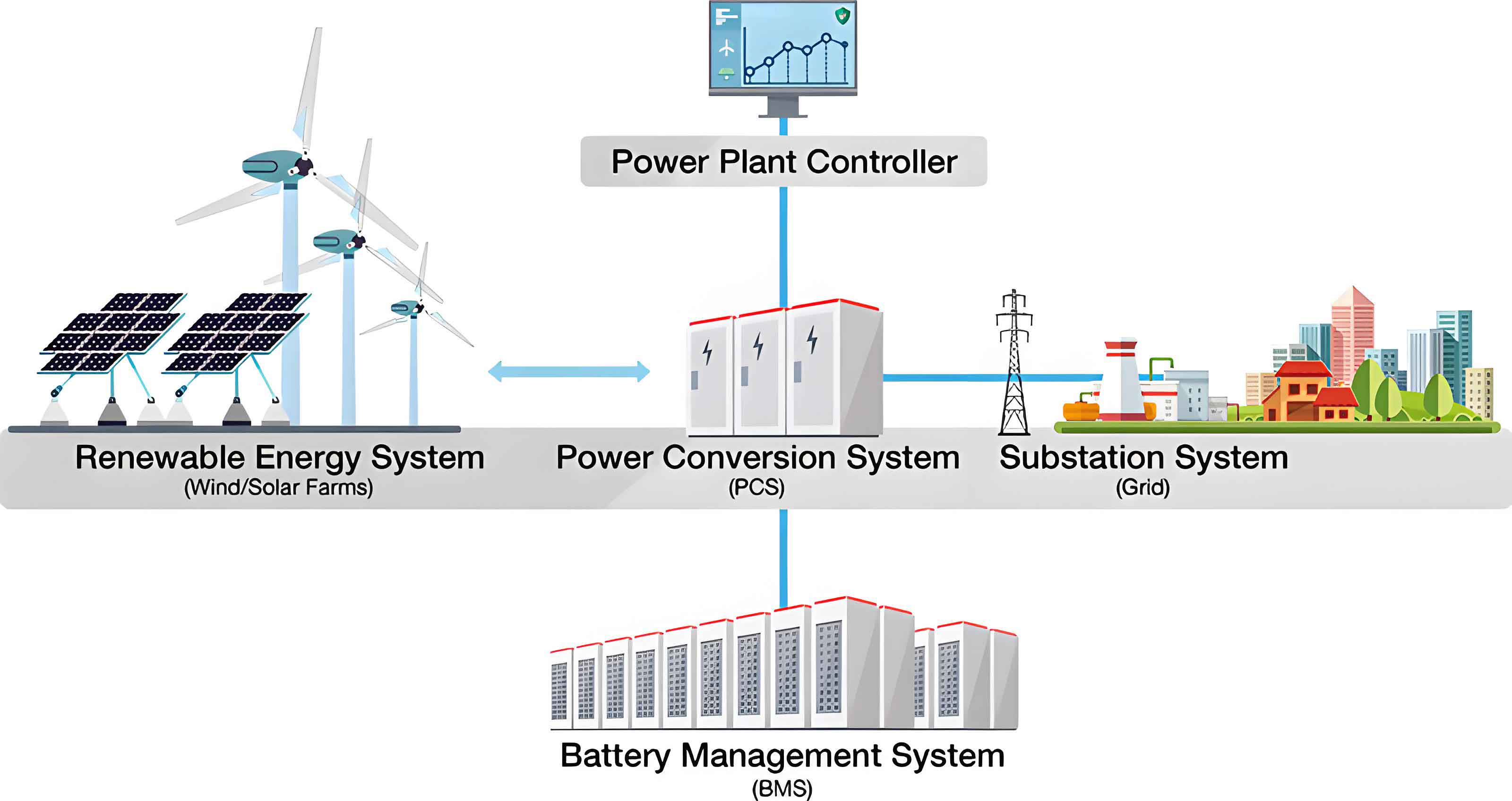
Renewable energy integration demands flexible and resilient power systems, where electrochemical energy storage systems play a crucial role. Distributed storage offers advantages in deployment and local consumption, but traditional series-parallel battery configurations suffer from cell inconsistency, leading to reduced efficiency and increased maintenance. To address these challenges, modular multilevel energy storage systems (MESS) have gained attention. In an MESS, each battery unit is paired with a power converter to form a submodule (SM). Cascading multiple SMs enables flexible energy management and fault isolation, significantly enhancing reliability and scalability. A typical configuration is illustrated below.
Effective energy management and fault isolation rely on accurate state-of-charge (SOC) and state-of-health (SOH) identification. Battery impedance is a key parameter for internal state characterization. By measuring the impedance response at multiple frequencies, the electrochemical impedance spectrum (EIS) can be obtained. Studies show that low-frequency impedance correlates with SOC, while high-frequency changes indicate aging, enabling SOH estimation. Traditional offline EIS measurement requires dedicated hardware and interrupts system operation. Hence, online EIS measurement integrated with the converter interface offers greater practical value. Existing methods based on DC/DC or DC/AC converters inject perturbations but often affect output power stability. This paper proposes a method that utilizes the half-bridge switching function of each SM to modulate the battery current, generating multi-frequency excitation without additional components. A coordinated control between test and compensation modules ensures that the total power drawn by the combined unit remains constant, eliminating power fluctuations. We detail the modulation principle, multi-frequency signal design, compensation strategy, and experimental validation.
Current Modulation Principle for Multi-Frequency Impedance Measurement
In a modular multilevel energy storage system, each submodule consists of a battery cell and a half-bridge converter, as shown in the system configuration. The half-bridge has two states: when the upper switch Q11 is on and lower Q12 is off, the battery is inserted into the DC bus; when Q11 is off and Q12 is on, the battery is bypassed. We define the switching function S(t) as in Table 1.
| Q11 state | Q12 state | S(t) | Submodule state |
|---|---|---|---|
| ON | OFF | 1 | Inserted |
| OFF | ON | 0 | Bypassed |
The battery current ibat(t) is given by:
$$i_{bat}(t) = S(t) \cdot i_{dc}(t)$$
where idc(t) is the DC bus current. When the energy storage system operates under stable power conditions, the DC bus current idc(t) is approximately constant due to the inductor Ldc. Let idc(t) ≈ Idc. Then:
$$i_{bat}(t) \approx I_{dc} \cdot S(t)$$
Thus, the battery current amplitude is determined by Idc, and its spectral content is fully determined by S(t). By designing a multi-frequency switching function, we can inject a wideband current excitation into the battery.
To measure impedance at target frequencies [f1*, f2*, …, fN*], we construct a multi-frequency sinusoidal signal fMFS(t):
$$f_{MFS}(t) = \sum_{n=1}^{N} \sin(2\pi f_n^* t)$$
The switching function S(t) is then obtained by taking the sign of fMFS(t):
$$S(t) = \begin{cases}
1 & \text{if } f_{MFS}(t) > 0 \\
0 & \text{if } f_{MFS}(t) < 0
\end{cases}$$
When S(t)=1, the bus current Idc flows into the battery; when S(t)=0, the battery is bypassed. This injects a current with harmonics at the target frequencies. By sampling the battery voltage vbat(t) and current ibat(t), we perform fast Fourier transform to extract their components at frequency fk*. The complex impedance is:
$$\hat{Z}(f_k^*) = \frac{\hat{V}_{bat}(f_k^*)}{\hat{I}_{bat}(f_k^*)}$$
This method allows simultaneous multi-frequency excitation in a single measurement cycle, reducing test time.
Coordinated Control for Power Stability
While switching the battery in and out injects perturbation current, it also modulates the power drawn by that submodule. For a test module conducting impedance measurement, the instantaneous power p1(t)=Vbat·Idc·S1(t) fluctuates. To eliminate this fluctuation without affecting the system, we introduce a compensation module with complementary switching. The compensation module’s switching function is the logical inverse of the test module’s function:
$$S_2(t) = 1 – S_1(t)$$
The combined unit (test + compensation) draws total power:
$$\begin{aligned}
p_{\text{test+comp}}(t) &= V_{bat} I_{dc} S_1(t) + V_{bat} I_{dc} S_2(t) \\
&= V_{bat} I_{dc} [S_1(t) + (1 – S_1(t))] \\
&= V_{bat} I_{dc}
\end{aligned}$$
This shows that the pair behaves like a virtual constant-power module consuming rated power Pmodule_rated at all times. Therefore, the system can maintain overall power balance by adjusting other modules normally. In practice, more than one compensation module can be used, provided that the sum of switching functions of all participating modules equals 1:
$$S_1(t) + S_2(t) + \cdots + S_k(t) = 1$$
This coordinated control ensures that the impedance measurement process does not disturb the system’s power flow, enabling uninterrupted online EIS measurement.
Simulation Validation
We built a simulation model with five submodules. Each submodule consists of 104 LFP cells in series (rated 332.8 V). The system establishes a 1000 V DC bus. Three modules are used in coordination (one test, one compensation, one constant) while two remain as spares. Key parameters are listed in Table 2.
| Parameter | Value |
|---|---|
| DC bus voltage | 1000 V |
| Number of modules | 5 |
| Single module voltage | 332.8 V (104 cells × 3.2 V) |
| Number of active modules | 3 |
| Test frequencies | [1, 2, 4, 10, 16, 25, 40] Hz |
The simulation results demonstrate that when module 1 starts EIS measurement at t=0 s without compensation, the DC bus voltage fluctuates. At t=0.5 s, module 3 enters compensation mode with complementary switching, and the voltage stabilizes. At t=1.0 s, module 2 takes over compensation, maintaining voltage. At t=1.5 s, module 1 exits test mode and enters bypass, while module 2 returns to normal operation. Throughout this process, module 1 continues impedance measurement unaffected. The bus current remains nearly constant due to the inductor, verifying that the coordinated control effectively cancels power ripple caused by the switching modulation. The simulated voltage and current waveforms confirm the stability of the system.
Experimental Validation
We built a small-scale experimental platform consisting of a DC source (50 V), a resistor load (5 Ω) to emulate the DC bus, and a single lithium-ion battery cell (EVE 32 Ah LFP). The test frequencies are set to [1, 2, 4, 10, 16, 25, 40] Hz. A TMS320F28377D controller generates the switching signals. The voltage ripple is amplified by a factor of 10⁵ for clear observation. Key parameters are listed in Table 3.
| Parameter | Value |
|---|---|
| DC source voltage | 50 V |
| Load resistance | 5 Ω |
| Inductance | 3.2 µH |
| Battery cell | EVE 32 Ah LFP |
| Test frequencies | [1, 2, 4, 10, 16, 25, 40] Hz |
| Controller | TI TMS320F28377D |
| Voltage ripple amplification | ×10⁵ |
The measured waveforms show the DC bus current (10 A/div), the upper gate drive signal (10 V/div), the battery current (10 A/div), and the processed battery voltage (1 V/div). The battery current exhibits a complex shape resulting from the multi-frequency switching modulation. FFT analysis of both current and voltage reveals dominant peaks precisely at the target frequencies, confirming effective excitation. Using the extracted components, we computed the impedance spectrum of the battery at two SOC levels (20% and 100%) and two temperatures (15 °C and 25 °C). The results are compared with measurements from a commercial impedance analyzer (Hioki BT4560). The Nyquist plots show excellent agreement between the proposed method and the reference instrument.
To quantify accuracy, we calculate the absolute percentage error (APE) at each frequency and the mean absolute percentage error (MAPE) across all frequencies.
$$APE(f_k) = \frac{|Z_{meas}(f_k) – Z_{ref}(f_k)|}{|Z_{ref}(f_k)|} \times 100\%$$
$$MAPE = \frac{1}{N} \sum_{k=1}^{N} APE(f_k)$$
The results are summarized in Table 4 for different operating conditions.
| Condition | Frequency (Hz) | APE (%) | MAPE (%) |
|---|---|---|---|
| 15 °C, SOC 20% | 1 | 4.2 | 3.8 |
| 2 | 3.1 | ||
| 4 | 2.8 | ||
| 10 | 4.5 | ||
| 16 | 3.9 | ||
| 25 | 4.1 | ||
| 40 | 3.5 | ||
| 15 °C, SOC 100% | 1 | 5.1 | 4.6 |
| 2 | 4.3 | ||
| 4 | 3.9 | ||
| 10 | 5.0 | ||
| 16 | 4.8 | ||
| 25 | 4.5 | ||
| 40 | 4.2 | ||
| 25 °C, SOC 100% | 1 | 4.0 | 3.6 |
| 2 | 3.2 | ||
| 4 | 2.9 | ||
| 10 | 3.8 | ||
| 16 | 3.5 | ||
| 25 | 3.7 | ||
| 40 | 3.4 |
The MAPE remains below 5% in all cases, confirming the high accuracy of the proposed method. Compared with existing online EIS techniques, our approach stands out due to its minimal impact on system power flow. Table 5 summarizes the comparison.
| Method | Excitation circuit | Excitation waveform | Impact on system | Test time |
|---|---|---|---|---|
| DC/DC | Perturbation in duty cycle | Square wave | Directly affects output power | >1 s |
| DC/AC | Inverter | Swept sine | Directly affects output power | 1.95 s |
| Reconfigurable circuit | Switches | Pseudo-random binary sequence | Directly affects output power | 1 s |
| Balancing circuit | Inductor | Approximate triangular | Minor effect | >1 s |
| Proposed method | Half-bridge selection | Multi-frequency current modulation | Negligible (compensation) | 1 s |
The proposed method achieves simultaneous multi-frequency measurement within 1 s without adding extra hardware, and the coordinated compensation scheme ensures that the energy storage system’s power exchange remains stable throughout the test.
Conclusion
We have presented an online electrochemical impedance spectroscopy measurement method tailored for modular multilevel energy storage systems. By designing a multi-frequency switching modulation for the half-bridge converter of each submodule, we inject targeted current excitation into the battery cell. The introduction of a test-compensation module pair with complementary switching ensures that the total power drawn from the system remains constant, thereby eliminating any disturbance to the normal operation of the energy storage system. Simulation confirms the effectiveness of the coordinated control in stabilizing the DC bus voltage. Experimental results with a 32 Ah LFP cell demonstrate that the measured impedance matches commercial analyzer values with an average relative error below 5% across a frequency range of 1–40 Hz and under different SOC and temperature conditions. The method requires no additional components beyond the existing converter interface and can be readily scaled to large-scale modular multilevel energy storage systems. This technique provides a reliable online monitoring tool for real-time battery state estimation and health management, contributing to the safe and efficient operation of modern energy storage systems.