
In the evolving landscape of architectural decoration, the integration of renewable energy systems, particularly solar panels, with building exteriors presents a significant opportunity for sustainable development. However, current methods often suffer from immature installation techniques and low space utilization, especially when combining solar panels with glass curtain walls. As an engineer involved in building decoration engineering, I have focused on addressing these challenges through innovative assembly technologies. This article details our approach to merging solar panels with glass panels using Building Information Modeling (BIM) and prefabricated units, transforming them into cohesive decorative elements for roofs and garden landscapes. Our goal is to enhance both aesthetic appeal and energy efficiency, ultimately contributing to carbon reduction in the construction sector.
The core of our work lies in reimagining traditional installation methods. Typically, roof solar panels and glass curtain walls are installed with additional skeleton layers, leading to complexity and inefficiency. By leveraging BIM technology, we have developed a system where solar panels and glass panels are integrated into prefabricated decorative units. This not only resolves issues like alternating arrangement of opaque solar panels and transparent glass panels but also unifies energy storage systems for optimal performance. Throughout this process, we emphasize the repeated use and strategic placement of solar panels to maximize their benefits.
Our project was implemented in a major building renovation, where we aimed to create a “light storage, direct, and flexible” structure that combines beauty with green functionality. The building covers approximately 20,000 square meters with 20 floors, and we targeted the roof canopy area for integration. Key objectives included using large-sized rectangular tubes as support columns and solar panel skeletons, forming a column-like structure that serves as a “lightweight roof.” This design allows for matching energy storage with photovoltaic systems, enabling self-consumption and reducing energy costs. Additionally, we employed BIM to analyze local climate data, determining the optimal installation angle and orientation for solar panels to enhance energy capture.
The engineering challenges were multifaceted. First, we utilized BIM to simulate urban environments and solar patterns, ensuring that solar panel placement maximizes sunlight exposure while minimizing carbon emissions. Second, we achieved integrated design by alternating high-transparency glass panels with photovoltaic glass panels in a diagonal layout, balancing发电量 with采光 effects. Third, we implemented concealed piping through assembly units, hiding photovoltaic cables within material grooves to maintain aesthetic coherence. Fourth, we selected dual-carbon materials, such as bifacial silicon cell solar panels and ultra-clear glass, to improve发电效率 and reduce power loss from shading. Fifth, we redesigned the roof with waterproofing and green plant protection layers, combining vegetation with insulation to mitigate urban heat island effects.
To illustrate the technical aspects, we can summarize key parameters using formulas. For instance, the optimal installation angle for solar panels in our location was determined based on latitude and solar altitude. The tilt angle $\theta$ can be calculated as:
$$ \theta = \phi – \delta $$
where $\phi$ is the local latitude and $\delta$ is the solar declination angle. For our project in a region similar to Chengdu, we set $\theta = 22^\circ$ for south-facing solar panels to maximize annual energy yield. The energy output of a solar panel system can be estimated as:
$$ E = A \cdot r \cdot H \cdot PR $$
where $E$ is the energy output (kWh), $A$ is the total solar panel area (m²), $r$ is the solar panel efficiency, $H$ is the annual solar irradiation (kWh/m²), and $PR$ is the performance ratio. In our case, we used 53 units of 500 Wp monocrystalline silicon solar panels and 16 units of 490 Wp panels, resulting in a total capacity. The首年发电量 was calculated as 29,000 kWh with a system efficiency of 87.41%, and over 25 years, the cumulative output is projected to be 718,700 kWh, reducing CO₂ emissions by approximately 548.7 tons.
The施工工艺流程 involved several meticulous steps, which we can outline in a table for clarity:
| Step | Description | Key Details |
|---|---|---|
| 1. BIM Model Positioning | Simulate solar patterns to determine solar panel placement | Used climate data; set orientation south at 22° angle |
| 2. Concrete Pouring | Pour foundation for support columns | Used C35 concrete with rebar; size 400 mm x 400 mm x 150 mm |
| 3. Fixing Rear Embedded Plates | Anchor plates to concrete bases | Used expansion screws for stability |
| 4. Measurement and Layout | Set out heights and slopes for框架 | Used水准仪; calculated vertical tube lengths based on drainage slope |
| 5. Rectangular Tube Installation | Weld tubes to form support framework | Included additional cantilever frames; ensured waterproofing |
| 6. Pipe Routing and Positioning | Lay cables for solar panels and lights | Concealed pipes within tubes; connected to control cabinet |
| 7. Surface Treatment of Tubes | Clean, rust-proof, and paint tubes | Applied fluorocarbon paint in three layers for durability |
| 8. Glass and Solar Panel Installation | Install panels in alternating pattern | Used aluminum压板 with bolts; connected circuits step-by-step |
| 9. Sealing and Finishing | Seal joints and hide cables | Applied silicone weatherproof sealant; conducted water spray tests |
| 10. Circuit System Installation | Set up inverters, switches, meters | Integrated with空调外机 for energy use |
During the solar panel installation, we paid special attention to the mounting details. The solar panels were fixed using block-shaped aluminum pressure plates with M6×60 mm bolts at 200 mm intervals. This method ensured secure attachment while allowing for thermal expansion. The nodes at the ends and centers of the solar panels were designed with insulation pads and silicone sealant to prevent leaks. For example, the stress distribution on a solar panel can be modeled using beam theory, where the deflection $\delta$ under uniform load $q$ is given by:
$$ \delta = \frac{5qL^4}{384EI} $$
where $L$ is the span, $E$ is the modulus of elasticity, and $I$ is the moment of inertia. This helped us verify the structural integrity of the solar panel supports.
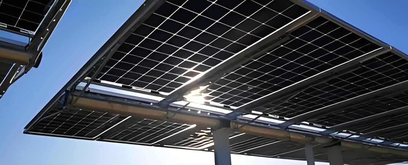
The image above illustrates the type of bifacial solar panel we employed, which captures sunlight from both sides to enhance efficiency. In our design, these solar panels were alternated with ultra-clear glass panels, creating a visually striking pattern while optimizing energy generation. The integration of such advanced solar panel technology was crucial for achieving high performance in limited roof spaces.
Quality control was paramount throughout the project. We adhered to several standards, including GB/T 50375-2016 for construction quality evaluation and GB 50794-2012 for photovoltaic construction. Specific measures included inspecting weld seams for defects like cracks or porosity, ensuring rust-proof coating was thoroughly applied, and verifying that sealant joints were smooth and bubble-free. For solar panel handling, we avoided踩踏 and conducted pre-installation checks for cracks. The fluorocarbon painting process involved three coats: primer, topcoat, and clear coat, each applied evenly to protect against weathering. After installation, we performed water spray tests for at least 5 minutes to confirm no leakage, documenting results for监理 approval.
Safety control followed standards such as JGJ 80-2016 for high-altitude work and JGJ 46-2005 for temporary electrical safety. We implemented fall protection systems, secured tools, and trained workers on handling solar panels and glass safely. Given the fragility of solar panels, we used lifting equipment to transport them to the roof, minimizing manual handling risks.
To further elaborate on the energy benefits, we can analyze the solar panel system’s performance metrics. The efficiency $\eta$ of a solar panel is defined as:
$$ \eta = \frac{P_{out}}{A \cdot G} \times 100\% $$
where $P_{out}$ is the power output, $A$ is the area, and $G$ is the solar irradiance. Our bifacial solar panels had an enhanced $\eta$ due to their dual-side absorption, which we estimated using empirical data. The table below summarizes key performance indicators for our solar panel array:
| Parameter | Value | Notes |
|---|---|---|
| Total Solar Panel Capacity | Approx. 34.57 kWp | From 53×500 Wp + 16×490 Wp solar panels |
| Annual Sunlight Hours | 870 hours | Based on local climate data |
| First-Year Energy Output | 29,000 kWh | Calculated with system efficiency 87.41% |
| 25-Year Cumulative Output | 718,700 kWh | Assumes linear degradation of solar panels |
| CO₂ Reduction | 548.7 tons | Over 25 years, per carbon计算标准 |
In terms of material science, the selection of solar panels involved considering factors like temperature coefficients and durability. The power temperature coefficient $\gamma$ for silicon solar panels is typically around -0.4% per °C, meaning output decreases as temperature rises. We mitigated this by ensuring adequate ventilation behind the solar panels, using the formula:
$$ P(T) = P_{STC} \cdot [1 + \gamma (T – T_{STC})] $$
where $P_{STC}$ is power at standard test conditions (25°C), and $T$ is the operating temperature. This informed our spacing and mounting decisions to prevent overheating and maintain solar panel efficiency.
The assembly process also incorporated modular design principles. Each prefabricated unit combined a solar panel and a glass panel, fabricated off-site to reduce on-site labor. The dimensions were standardized, allowing for quick installation via diagonal交叉 assembly. This approach minimized waste and accelerated project timelines, aligning with industrial construction trends. We calculated the time savings using a simple relation:
$$ T_{saved} = N \cdot (t_{traditional} – t_{prefabricated}) $$
where $N$ is the number of units, and $t$ represents installation times. For our 69 panels, we estimated a 30% reduction in installation time compared to conventional methods.
Moreover, the integration of solar panels with building management systems enabled real-time monitoring. We used sensors to track energy production from each solar panel, feeding data into a central dashboard. The energy balance for the building can be expressed as:
$$ E_{consumed} = E_{solar} + E_{grid} – E_{stored} $$
where $E_{solar}$ is from solar panels, $E_{grid}$ is grid power, and $E_{stored}$ is in batteries. Our system prioritized solar panel output for direct use, with excess stored or fed back, enhancing overall efficiency.
In conclusion, this project demonstrates a viable path for merging architectural decoration with renewable energy. By innovating with solar panel and glass curtain wall assembly, we have created a solution that addresses space utilization, aesthetic harmony, and energy sustainability. The use of BIM and prefabrication not only streamlined construction but also ensured precision in solar panel placement for maximum yield. Looking ahead, we believe such technologies can be scaled to other buildings, promoting绿色降碳 across the industry. The success of this initiative hinges on continuous improvement in solar panel materials, smart grid integration, and collaborative design, all of which we are committed to advancing in future work.