
Our team has been deeply involved in the development and installation of hyperbolic wave-shaped dragon scale solar panels, a cutting-edge technology that integrates photovoltaic generation with architectural aesthetics. This article details the complete construction process, from advanced material preparation to on-site installation and quality assurance, emphasizing the critical role of innovative manufacturing and precise engineering in achieving high-performance solar panels.
1. Introduction to Dragon Scale Solar Panels
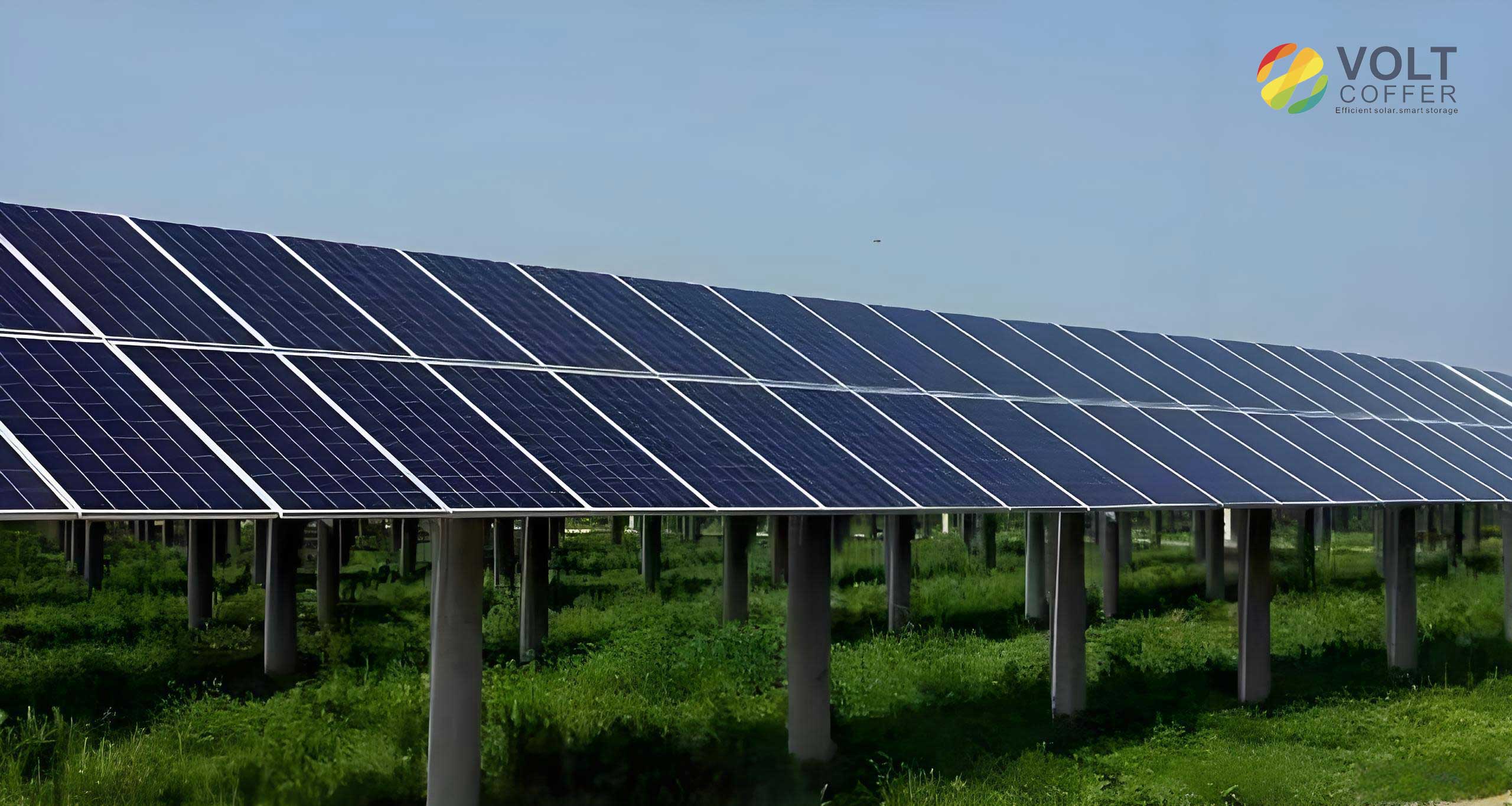
Dragon scale solar panels are designed to conform to curved roof surfaces, capturing sunlight from multiple angles throughout the day. Their unique scale-like structure not only provides striking visual effects — with shimmering waves under sunlight — but also enhances light trapping. The textured surface increases the refractive utilization of light, converting approximately 80% of incident solar radiation into electrical energy. Even under low-light conditions, these panels generate significant thermal energy. By incorporating perovskite quantum dot technology, the photoelectric conversion efficiency of our solar panels reaches about 30%, a substantial improvement over conventional modules. Additionally, an aerospace-grade anti-glare film is applied to the surface to mitigate light pollution, making these solar panels both efficient and environmentally friendly.
2. Construction Process Flow of Dragon Scale Solar Panels
The construction of hyperbolic wave-shaped dragon scale solar panels involves a meticulously orchestrated sequence of steps. Each stage is critical to ensure the final product meets the highest standards of efficiency, durability, and aesthetics.
2.1 Perovskite Quantum Dot Preparation
We started by synthesizing high-quality perovskite quantum dots to enhance the photovoltaic performance of our solar panels. The precursor liquids included lead oleate and ytterbium oleate. After mixing and stirring these precursors, we added octadecene, oleic acid, oleylamine, lead oleate, aluminum acetate basic, and cesium acetate into a specialized reactor. The mixture was held under vacuum at high temperature, then heated to the process temperature. A blend of trimethylchlorosilane and trimethylbromosilane was injected rapidly. The reaction was quenched in an ice-water bath. To the resulting solution, we added cadmium oleate, followed by heating and stirring. The solution underwent centrifugation, dispersion in hexane, and purification. A subsequent passivation step involved adding an ethanol solution of cadmium chloride, mixing, and centrifuging again. The purified quantum dots were dispersed in toluene, then combined with oleylamine chloride and octadecene, heated, stirred, and finally purified to obtain the final perovskite quantum dot solution. The entire synthesis process was carefully controlled to achieve uniform particle size and high photoluminescence quantum yield, which directly boosts the efficiency of the solar panels.
2.2 Cell Placement
The internal battery cell placement of each solar panel follows a strict sequence: pretreatment, layout, and welding.
- Pretreatment: Cells with defects such as missing corners, cracks, edge chipping, or surface contamination (fingerprints/oil) were rejected. We ensured no active layer peeling on the perovskite cells.
- Cell Layout: According to the design, we determined the number of strings and cells per string (e.g., 60-cell module = 6 strings × 10 cells). The layout table was leveled (error ≤ 0.1 mm/m) and covered with an anti-static mat. String spacing was controlled between 5–8 mm to facilitate bus bar connection without shading.
- Cell Welding: Ribbon was placed flat on the bus bars of each cell, with alignment deviation ≤ 0.2 mm. Soldering iron pressure was applied for 1–2 seconds per point to ensure full wetting (no cold or false soldering). Ribbon must have no offset or lifting, and cells must have no hidden cracks. Each string had consistent ribbon lengths (tolerance ±1 mm).
- Inspection: Visual inspection confirmed no cell shift, ribbon lifting, or cracks. Electrical testing measured open-circuit voltage per string to match design values and ensure no short circuits.
2.3 Panel Encapsulation
Encapsulation integrates cells, glass, and other materials through lamination and curing. For perovskite-based solar panels, we employed low-temperature lamination to avoid degrading the perovskite active layer.
The lamination parameters are summarized in the table below:
| Parameter | Value |
|---|---|
| Lamination Temperature | 60–80 °C |
| Vacuum Level | < -0.09 MPa |
| Vacuum Hold Time | 8–10 min |
| Pressure | 0.05–0.08 MPa |
| Pressure Hold (Curing) Time | 15–20 min |
| Cooling before Removal | Below 40 °C |
$$ T_{\text{lam}} \in [60^\circ\text{C}, 80^\circ\text{C}], \quad P_{\text{vac}} < -0.09\,\text{MPa}, \quad t_{\text{vac}} = 8\,\text{min} \,\text{to}\, 10\,\text{min} $$
After lamination, we trimmed excess encapsulant and backsheet with a utility knife, ensuring smooth edges. A weather-resistant sealant was applied along all four edges of the module (between glass and backsheet), with a seal width ≥ 5 mm and thickness ≥ 3 mm, free of bubbles or gaps. This seal completely covered the lamination edge to prevent moisture ingress.
2.4 Packaging and Testing
After demolding, we cleaned the edges of each dragon scale solar panel, removing excess encapsulant and weather film. Junction boxes were installed and cured under controlled temperature and humidity. Each module underwent rigorous electrical testing:
- Insulation/Dielectric Withstand Test: High voltage was applied to verify insulation integrity, ensuring safety compliance.
- Current-Voltage (I-V) Characteristic Test: Under standard test conditions (STC: 1000 W/m², 25 °C, AM 1.5), we measured the output power of every solar panel. Only panels passing within specified tolerance were accepted; defective units were scrapped.
Accepted panels were labeled with specifications, packed into cartons or wooden crates, and stored in the warehouse. The entire test data was recorded for traceability.
3. Installation Design and Deepening
Our team developed a specialized connection system to accommodate the hyperbolic wave-shaped geometry of the roof, ensuring uniform gaps between adjacent solar panels and achieving the desired visual effect.
3.1 Connection Method Selection
We evaluated two connection approaches:
- Pad-type connection: Each solar panel had two holes, connected via rubber pads and bolts directly between panels.
- Frame-edge connection: Each solar panel had one hole, fixed to dedicated aluminum brackets and aluminum support plates, without direct panel-to-panel connection. This method provided superior alignment accuracy.
After comparative analysis, the frame-edge connection was chosen because it produced uniform joint gaps and a better assembly appearance.
3.2 Y-Shaped Aluminum Bracket Design
The Y-shaped aluminum bracket was engineered for multi-axis adjustability. It consists of an aluminum clamp, a rotating angle adjustment plate, an assembly angle plate, and an aluminum rotating connector. Key features include:
- Vertical adjustment via elongated slots with serrated edges for precise control and grip.
- Horizontal rotation adjustment by the rotating angle plate.
- Inclination angle adjustment through a wrap-style movable connection at the top.
This Y-bracket enables three degrees of freedom: vertical displacement, planar rotation, and tilt angle. The adjustment range can be expressed as:
$$ \Delta z \in [-10\,\text{mm}, +10\,\text{mm}], \quad \Delta \theta \in [-15^\circ, +15^\circ], \quad \Delta \phi \in [-10^\circ, +10^\circ] $$
Such flexibility was essential to match the double-curved wave surface of the roof and maintain uniform panel gaps.
4. On-Site Installation Sequence
4.1 Main and Secondary Keel Installation
The steel keels were prefabricated in the factory and transported to site. Using tower cranes, they were lifted onto pre-installed supports and then manually adjusted to exact positions. Temporary tack welding was performed first, followed by full welding after precise measurement verification. Secondary keels used either 80 mm × 80 mm × 5 mm square steel tubes (for single-curvature areas) or φ89 mm × 5 mm round steel tubes (for double-curved torsion areas). At expansion joints, a 80 mm × 5 mm steel sleeve was inserted.
4.2 Support and Mounting Plate Installation
After the roof panels were installed, we snapped chalk lines to mark the starting position for the Y-brackets. The Y-bracket and aluminum support plate were assembled as a unit. If the roof panels had deviations, the adjustable features of the Y-bracket were used to correct the position before proceeding.
4.3 Solar Panel Installation
The dragon scale solar panels were installed from low to high in a layered overlapping pattern. We first positioned and fixed the lowest row of panels, then progressed upward according to design dimensions. Every two rows, we used a total station to measure the coordinates of three corners of the installed solar panels. If errors exceeded the predetermined tolerance, immediate adjustments were made to prevent error accumulation. Once each solar panel was aligned, aluminum card slots were embedded on both sides of the base plate to secure it.
4.4 Wiring and Cable Management
Our roof deployed approximately 13,000 dragon scale solar panels. The large number and the irregular curved layout created unprecedented routing complexity. We added cable trays between the solar panels and the steel structure to conceal the wiring, maintaining the roof’s aesthetic appearance while ensuring organized cable routing for easy construction and future maintenance. Building Information Modeling (BIM) technology was used to detect potential collisions among different trades. Inverters were centrally placed in optimal locations to minimize cable lengths, reducing material costs and simplifying maintenance. This optimization scheme proved highly effective for large-scale solar panel roof projects.
5. Quality Control Measures
Stringent quality control was implemented throughout the entire process to ensure the performance and longevity of the hyperbolic wave-shaped dragon scale solar panels.
5.1 Protection of Finished Products
The double-curved irregular dragon scale solar panels have delicate surface coatings. We used customized transport racks with flexible cushioning materials between each panel to avoid scratches and impacts. During transport, vehicle speed was controlled to minimize vibration. Storage areas were dry, well-ventilated, and free from corrosive gases. Panels were placed on elevated supports, tilted, and covered with dust-proof cloth. During construction, workers were prohibited from stepping directly on solar panels; dedicated walkways were installed. For concurrent trades, installed solar panels were protected with temporary covers. After installation, any surface stains were cleaned using neutral detergents and soft tools to prevent chemical corrosion or physical damage. Warning signs were placed around the roof area to prevent accidental damage from subsequent activities.
5.2 Welding Quality Control
Before welding, all welders underwent specialized training and qualification tests focused on the double-curved structure. Welding equipment was calibrated to ensure stable current and voltage. During welding, parameters such as current, travel speed, and electrode angle were precisely controlled according to the welding procedure specification. For high-curvature zones, techniques like skip welding and symmetric welding were employed to minimize distortion. After each pass, slag and spatter were removed, and the weld surface was visually inspected for smoothness, porosity, slag inclusions, and cracks. Upon completion, non-destructive testing (ultrasonic or radiographic) was performed per code requirements. Defective welds were repaired (with a maximum number of repairs per code) and re-tested. Finally, all welds received anti-corrosion coating to prevent rust and structural weakening.
5.3 Bolted Connection Quality Control
- Pre-installation inspection: Bolts, nuts, and washers were checked for specifications, material grade, and defects (cracks, rust). Contact surfaces were ground clean, free of oil and rust.
- Installation: Torque wrenches were used to tighten bolts in stages (initial snug then final torque) with recorded torque values. For different locations and bolt sizes, the designated torque was strictly followed to avoid over-tightening (damaging panels) or under-tightening (loose connections). Bolt perpendicularity was maintained.
- Post-installation inspection: Every bolt was checked for missing or loose conditions. Periodic re-torque audits were scheduled.
We defined the tightening torque for M8 stainless steel bolts as:
$$ T_{\text{M8}} = 20\,\text{N}\cdot\text{m} \pm 2\,\text{N}\cdot\text{m} $$
For M10 bolts:
$$ T_{\text{M10}} = 35\,\text{N}\cdot\text{m} \pm 3\,\text{N}\cdot\text{m} $$
5.4 Electrical Performance Verification
All solar panels were tested both at the factory and after installation. The key electrical parameters monitored are listed in Table 2.
| Parameter | Condition | Acceptance Criteria |
|---|---|---|
| Open-Circuit Voltage (Voc) | STC | ≥ 38.5 V per module |
| Short-Circuit Current (Isc) | STC | ≥ 9.2 A per module |
| Maximum Power (Pmax) | STC | ≥ 350 W (tolerance +5%/-3%) |
| Insulation Resistance | 1000 V DC | ≥ 40 MΩ |
| Dielectric Withstand | 3000 V DC, 1 min | No breakdown or leakage |
The fill factor (FF) of the module can be calculated as:
$$ FF = \frac{P_{\text{max}}}{V_{\text{oc}} \times I_{\text{sc}}} $$
We maintained a fill factor above 0.75 for all shipped solar panels.
6. Results and Benefits
The dragon scale solar panels installed on the roof generate electricity that powers lighting, air conditioning, and other building systems. Annually, the system saves approximately 1.2 × 10⁶ kWh of electricity, corresponding to a carbon reduction of 1,043 tons per year:
$$ \text{Carbon reduction} = 1.2 \times 10^6 \, \text{kWh} \times 0.869 \, \text{kg CO}_2/\text{kWh} \approx 1.043 \times 10^6 \, \text{kg CO}_2 $$
Compared with traditional construction methods, our optimized workflow — including deepening design, research & development, prefabrication, and installation — significantly reduced the processing cycle time. Early project completion saved labor costs, equipment rental fees, and improved capital turnover efficiency, delivering substantial overall economic benefits.
7. Conclusion
The hyperbolic wave-shaped dragon scale solar panels represent a breakthrough in photovoltaic building integration. Our team successfully developed a comprehensive construction process covering perovskite quantum dot preparation, cell placement, low-temperature encapsulation, packaging test, and precision installation using Y-shaped adjustable brackets. The quality control measures — especially in protection, welding, bolting, and electrical verification — ensured that every solar panel met stringent performance standards. The project not only achieved an aesthetically pleasing wave-form roof but also delivered impressive energy savings and carbon reduction. This approach offers a replicable model for future large-scale curved solar panel installations, advancing the adoption of sustainable building-integrated photovoltaics.