
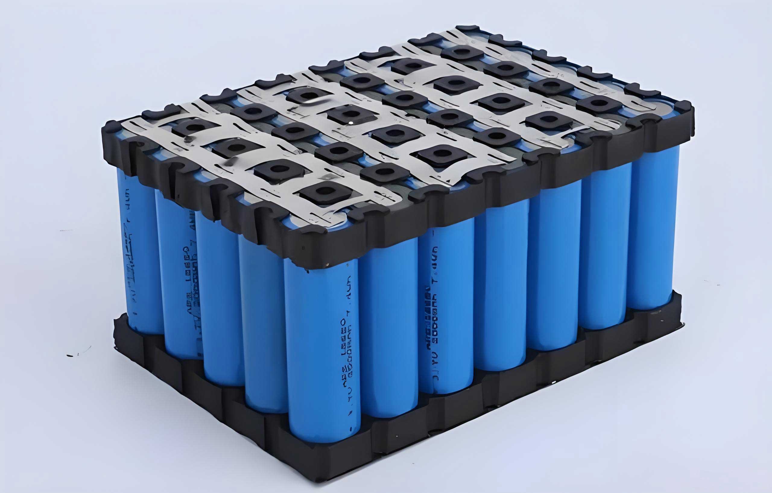
The rapid expansion of grid-scale energy storage, driven by the global transition to renewable energy, has positioned lithium-ion battery technology at the forefront. Among various chemistries, the lithium iron phosphate (lifepo4 battery) has gained significant traction due to its inherent thermal stability, long cycle life, and cost-effectiveness. However, as evidenced by major fire incidents in energy storage systems (ESS) worldwide, no commercial lifepo4 battery is entirely immune to the risk of thermal runaway under extreme abuse conditions. The consequence of a single cell’s failure can cascade into a module- or container-level fire, posing severe threats to safety, property, and grid reliability. Therefore, developing and implementing an effective, multi-layered fire protection strategy is not merely an add-on but a fundamental requirement for the safe deployment of lifepo4 battery energy storage systems. This article, from my perspective as a practitioner in the field, delves into the fire dynamics of LiFePO4 batteries, critically analyzes common extinguishing agents, and synthesizes a comprehensive protection framework based on practical system design.
Decoding the Fire Hazard: Thermal Runaway in LiFePO4 Batteries
The root cause of ESS fires lies in the phenomenon of thermal runaway. It is a positive feedback loop where exothermic reactions within a lifepo4 battery generate heat faster than it can be dissipated, leading to a rapid, uncontrolled temperature increase. Understanding this chain of events is crucial for designing effective countermeasures.
The thermal runaway process in a lifepo4 battery typically follows a sequence of internal chemical decompositions:
- Initial Stage (80°C – 120°C): The Solid Electrolyte Interphase (SEI) layer on the anode, which is metastable, begins to exothermically decompose. This reaction can be represented as:
$$ \text{SEI (e.g., } (CH_2OCO_2Li)_2\text{)} \xrightarrow{\Delta} \text{Li}_2\text{CO}_3 + \text{Gases (C}_2\text{H}_4, \text{CO, etc.)} + \text{Heat} $$
Once the SEI layer is consumed, the exposed lithiated carbon anode reacts violently with the organic electrolyte. - Acceleration Stage (120°C – 200°C): The separator, usually made of polyethylene (PE) or polypropylene (PP), melts and collapses, leading to internal short circuits. Simultaneously, the binder material (often PVDF) in the electrode can react with the lithium. The electrolyte solvents (e.g., EC, DEC, EMC) undergo decomposition, releasing significant amounts of flammable gases.
- Venting and Ignition (>200°C): Although the LiFePO4 cathode itself is more thermally stable than layered oxide cathodes (like NMC or NCA), it can still decompose at very high temperatures, releasing oxygen. The internal pressure from generated gases (H₂, CO, CH₄, C₂H₄, etc.) forces the cell’s safety vent to open, ejecting a jet of hot electrolyte vapor and particulate matter. Upon contact with an ignition source (a spark from the internal short or external heat), this jet ignites, creating a challenging three-dimensional flame.
The combustion of a failing lifepo4 battery is therefore a complex, multi-class fire (Class A: solid particulates/electrode materials, Class B: flammable liquid electrolyte, Class C: electrical components initially energized). The continuous internal exothermic reactions act as a persistent reignition source, making suppression and, more importantly, cooling paramount.
Critical Analysis of Fire Extinguishing Agents for LiFePO4 Battery Fires
No single “silver bullet” extinguishing agent exists for lifepo4 battery fires. The ideal agent must address two concurrent challenges: 1) rapidly suppressing the open flame, and 2) providing profound and sustained cooling to quench the internal thermal runaway reaction and prevent cell-to-cell propagation. The table below provides a comparative analysis of agents commonly considered or deployed in lifepo4 battery energy storage systems.
| Extinguishing Agent | Primary Mechanism | Flame Knockdown for LiFePO4 | Cooling Capacity | Reignition Inhibition | Practical & Safety Considerations |
|---|---|---|---|---|---|
| HFC-227ea (Heptafluoropropane) | Chemical inhibition (radical scavenging), minor cooling. | Excellent. Rapid flame suppression in enclosed spaces. | Poor. Minimal cooling effect on cells. | Very Poor. Cells continue thermal runaway, high probability of reignition. | Mature technology, clean agent. Requires sealed enclosure. Potential for toxic HF generation if exposed to extreme heat. |
| FK-5-1-12 (Novec 1230 / Perfluorohexanone) | Predominantly cooling (high heat of vaporization), combined with chemical inhibition. | Very Good. Effective at suppressing visible flames. | Good. Better cooling than HFCs due to phase change. | Moderate. Cooling can delay but may not stop deep-seated reactions; reignition possible. | Clean, non-conductive, low toxicity. Higher cost. Requires precise nozzle placement for targeted application. |
| Aerosol (Condensed/SLP) | Chemical inhibition (radical scavenging by K⁺ or other metal ions). | Moderate to Poor. May not effectively penetrate and suppress jet fires. | Poor. Generation is exothermic; adds minimal cooling. | Poor. No residual cooling effect. | Compact, no pressure vessels. Produces obscuring residue, corrosive by-products (K₂CO₃), and presents a secondary ignition risk during deployment. |
| Water Mist / Fine Water Spray | Overwhelming cooling, oxygen displacement by steam, attenuation of radiant heat. | Excellent when applied directly. Steam can sometimes spread flame initially if not targeted. | Exceptional. High latent heat of vaporization provides deep, sustained cooling. | Excellent. Continuous application can halt thermal runaway propagation. | Highly effective but controversial. Risk of electrical conductivity, potential for gas generation (H₂ from Li reaction), and water damage. Requires drainage and clean-up. |
| Hybrid Systems (e.g., Gas + Wetting Agent) | Combination: gas for quick knockdown, liquid for cooling and encapsulation. | Excellent (from gas component). | Good (from liquid component). | Good. Liquid residue can provide ongoing thermal barrier. | Emerging technology. Aims to combine strengths. Complexity, cost, and long-term reliability of mixed systems need validation. |
The analysis leads to a critical conclusion: while agents like HFC-227ea and FK-5-1-12 are excellent at achieving the first objective (flame knockdown), they are inherently limited in achieving the second (deep, lasting cooling). Water is uniquely capable of the second objective but poses practical challenges for direct, always-on installation within electrical enclosures due to conductivity and collateral damage concerns.
A Synthesized, Multi-Stage Fire Protection System Design
Given the limitations of single-agent systems, a holistic, defense-in-depth strategy is essential for lifepo4 battery energy storage systems. This strategy is based on the principle of staged response, moving from early warning to targeted suppression and finally to mass cooling. The following framework outlines the key subsystems and their integration logic.
1. Early Detection and Warning Subsystem
Preventing a fire is superior to fighting one. Advanced detection is the first critical layer. A multi-sensor approach is mandatory:
- Gas Detection (Earliest Warning): Deploying tunable diode laser absorption spectroscopy (TDLAS) or catalytic bead sensors within battery racks to detect early off-gassing (CO, H₂, VOCs) provides the earliest possible warning, often tens of minutes before thermal runaway.
- Thermal Detection: Distributed Temperature Sensing (DTS) using fiber optics or an array of spot heat detectors can identify developing hot spots within a lifepo4 battery module.
- Smoke Detection: Very Early Smoke Detection Apparatus (VESDA) or aspirating smoke detectors offer sensitive smoke detection for the overall enclosure volume.
The system control logic should initiate pre-alarms and safety protocols (e.g., derating charging, activating ventilation) upon gas detection, escalating to full fire alarm upon confirmation from thermal or smoke sensors.
2. Ventilation and Pressure Management Subsystem
Upon early gas detection, an explosion-proof ventilation system must activate to dilute and remove flammable gases, maintaining concentrations below the Lower Explosive Limit (LEL). This subsystem is governed by:
$$ \frac{dC}{dt} = G – \lambda C $$
where \( C \) is gas concentration, \( G \) is the generation rate from the failing lifepo4 battery, and \( \lambda \) is the air exchange rate from ventilation. The goal is to keep \( C < 25\% \text{ LEL} \). Simultaneously, explosion venting panels or doors rated for the specific cubic volume of the container must be installed to safely relieve pressure in case of a deflagration, preventing structural failure.
3. Primary Suppression Subsystem (Targeted Knockdown)
This is the first active firefighting layer. Based on the analysis, a perfluorohexanone (FK-5-1-12) system is a strong candidate. Its design should be targeted, not just volumetric. Instead of flooding the entire container, the system should use pipe networks with nozzles directly aligned to spray into individual battery racks or even modules. This “direct injection” approach maximizes the agent’s contact with the cell surfaces, improving both flame knockdown and cooling efficiency for the affected cluster. The system should be triggered automatically upon confirmed fire alarm (e.g., thermal + smoke detection).
4. Secondary Cooling and Sustained Suppression Subsystem (Bulk Cooling)
Recognizing that the primary agent may not prevent reignition, a secondary system must be in place. This is where a carefully designed water-based system comes in. It is not intended as the first responder but as the final mitigator. This system can be a dedicated deluge or mist system inside the container, or more practically, an integrated interface for external firefighting. The design includes:
- Standardized external fire department connection (FDC) ports on the container.
- An internal piping manifold and spray nozzles positioned over battery racks.
- Thermal-shutoff valves to prevent accidental discharge.
The control logic manually activates this system following the primary suppression discharge if temperatures remain elevated or reignition is observed (via continuous thermal monitoring). This allows firefighters to safely connect and flood the specific container with large volumes of water for extended cooling without risking electrical shock from live components, as the ESS should be fully disconnected by this stage.
5. Integration and Control Logic
The effectiveness of the entire protection strategy for a lifepo4 battery energy storage system hinges on a unified control system. The following sequence diagram summarizes the integrated logic:
Step 1 (Pre-Alarm): Gas Detection > Activate Ventilation, Signal BMS to Derate/Stop, Alert Operators.
Step 2 (Fire Alarm): Thermal/Smoke Detection Confirmation > Isolate HVAC, Shut Down DC & AC Power, Sound Evacuation Alarm, Activate Primary FK-5-1-12 Suppression.
Step 3 (Post-Suppression & Monitoring): Monitor Rack Temperatures Continuously.
Step 4 (Secondary Response): IF Temperatures > Safe Threshold (e.g., 80°C) OR Reignition Detected > Manually Activate Internal Water Spray System via External FDC.
Beyond Firefighting: System-Level Risk Mitigation
A truly safe lifepo4 battery energy storage system integrates fire protection with inherent safety design:
- Cell and Module Design: Using flame-retardant electrolytes, ceramic-coated separators, and module designs with physical barriers (metal plates, aerogel) to slow down cell-to-cell propagation.
- Thermal Management: Robust liquid cooling systems that maintain uniform temperature and can handle emergency cooling loads.
- Electrical Protection: Advanced Battery Management Systems (BMS) with precise voltage/temperature monitoring, diagnostic algorithms for early fault detection, and rapid disconnect capabilities.
- Siting and Compartmentalization: Installing ESS units with adequate separation, fire walls, and containment berms to isolate potential incidents.
The fire protection system is the last line of defense in this multi-barrier approach.
Conclusion and Forward Perspective
The fire risk associated with lifepo4 battery energy storage systems is a complex, multi-faceted challenge that cannot be solved by a single extinguishing agent. The characteristic thermal runaway behavior of a lifepo4 battery demands a response strategy that sequentially addresses gas management, flame knockdown, and, most critically, profound thermal quenching. The synthesized strategy proposed here—layering early gas detection, targeted clean agent suppression (like perfluorohexanone), and a managed water cooling interface—creates a robust defense-in-depth framework. This approach acknowledges the strengths and limitations of each technology, deploying them in a staged sequence to maximize effectiveness and practicality.
Future advancements will likely focus on smarter, more integrated systems. This includes BMS with predictive analytics for failure, advanced suppression agents with superior cooling properties, and automated, targeted water mist systems that can activate safely post-electrical isolation. The goal for the industry is to make the fire protection system for a lifepo4 battery energy storage system as reliable, predictable, and passive as possible, ensuring that this critical technology can fulfill its role in the clean energy grid with the highest level of safety assurance.