
In my analysis, I treat the medium-voltage grid as an operating environment in which distributed generation must behave less like a passive source and more like an actively managed power-electronics interface. The medium-voltage directive for distributed generation systems requires capabilities that go well beyond simple maximum-power injection. For solar inverters, this means that fault ride-through is not only a protection issue but also a coordinated control problem involving reactive current, active power reduction, dc-bus voltage regulation, current limiting, and sequence-component management. I focus here on a three-phase three-level solar inverter connected to a medium-voltage network through a two-stage power conversion architecture. The first stage is a boost converter that performs maximum power point tracking for the photovoltaic source. The second stage is a three-phase three-level grid-connected solar inverter that regulates grid current, dc-bus voltage, reactive power, and fault behavior. My objective is to formulate a coherent control strategy that allows solar inverters to remain connected during symmetrical and asymmetrical grid faults while respecting the medium-voltage directive.
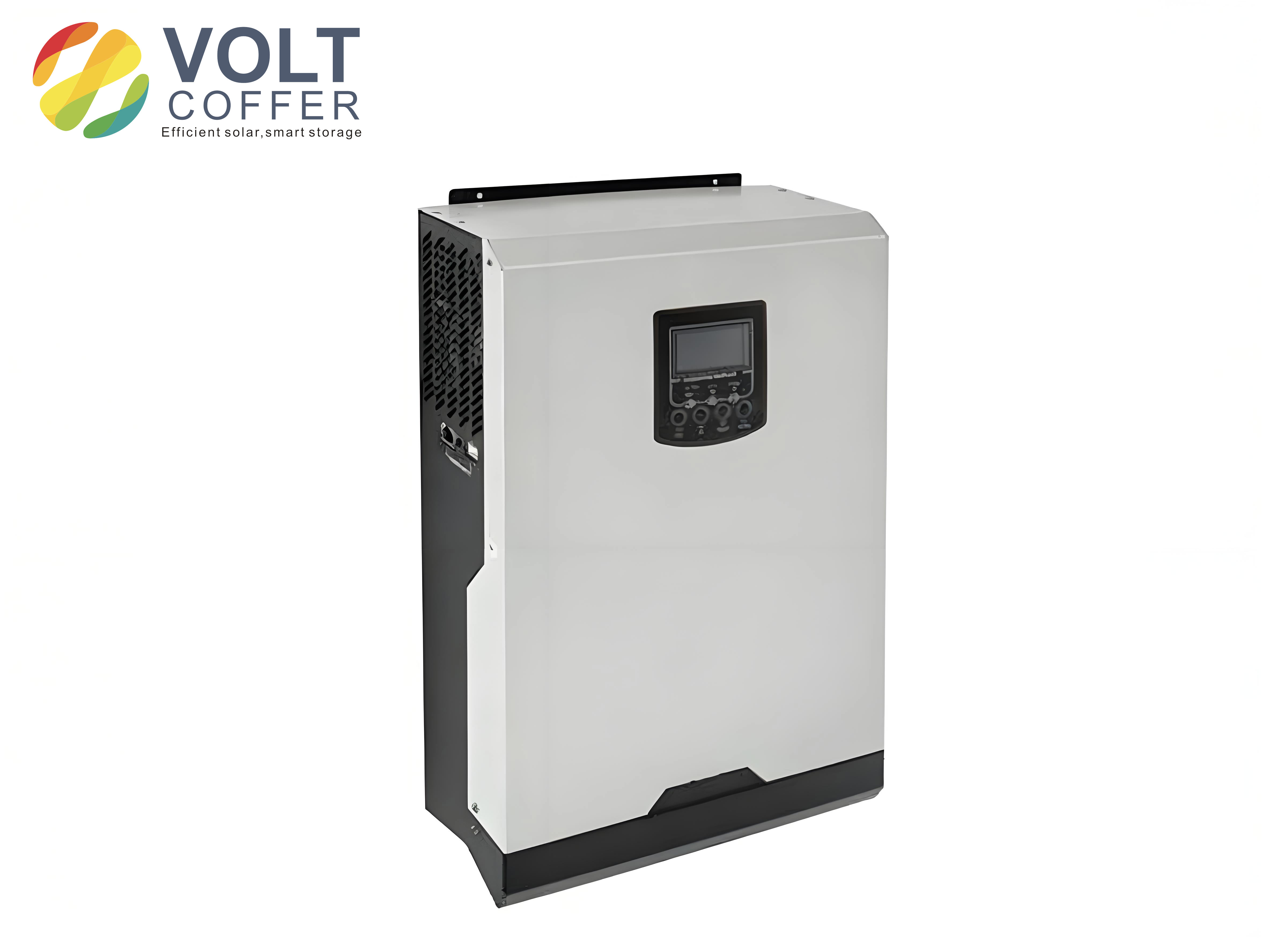
The medium-voltage directive introduces four families of requirements that shape the design of solar inverters: static and dynamic voltage support, maximum permissible short-circuit current, active-power output management, and reactive-power compensation. In photovoltaic systems, the short-circuit current is naturally limited by the photovoltaic array, and the difference between short-circuit current and maximum-power current is usually modest. Therefore, I do not need to add a separate short-circuit current limiter in the same way that some wind or engine-based distributed generators do. Instead, I concentrate on the three remaining functions: voltage support, active-power management, and reactive-power compensation. These functions must coexist with the conventional boost control, maximum power point tracking, and three-phase vector control of the solar inverter.
| Function | Purpose | Main control variable | Impact on solar inverters |
|---|---|---|---|
| Static voltage support | Maintain power quality and support steady-state voltage | Power factor or reactive power reference | Adjusts reactive current while preserving active power priority |
| Dynamic voltage support | Support voltage during symmetrical faults | Reactive current magnitude | Requires fast reactive current injection within milliseconds |
| Active-power management | Limit current and stabilize dc bus during faults | Active-power reference and MPPT derating | Reduces photovoltaic power when required |
| Frequency-active power control | Reduce active power under over-frequency | Frequency-dependent active-power reduction | Changes MPPT operating point |
| Asymmetrical fault control | Suppress negative-sequence current | Positive and negative sequence current references | Requires dual current control |
I begin with the system architecture. The boost converter is placed between the photovoltaic array and the dc bus. Its output current charges the dc-bus capacitor, while the three-phase three-level solar inverter transfers power from the dc bus to the grid. The boost stage implements maximum power point tracking by sampling the photovoltaic voltage and adjusting the duty cycle so that the array operates near its maximum power point. The output of the MPPT algorithm is used as the input-voltage reference for the boost converter. When fault ride-through or active-power curtailment is required, the MPPT reference is shifted so that the photovoltaic array moves away from its maximum power point and toward the open-circuit voltage side. This derating strategy is important because the slope of the photovoltaic characteristic is steeper near open-circuit voltage, which makes power reduction more controllable.
The grid-side solar inverter uses a three-level topology and a vector-control structure. The dc-bus voltage loop generates an output-current amplitude reference. This amplitude is then distributed between the d-axis and q-axis current references according to the desired active and reactive power. In the original unity-power-factor design, the q-axis current reference is set to zero, so the solar inverter injects only active current. With the medium-voltage directive, however, the q-axis reference becomes a controlled variable. The solar inverter must be able to receive an external dispatch signal for power factor or reactive power and must also respond automatically to grid voltage deviations.
I derive the dc-bus voltage dynamics because they explain why active-power management is coupled with reactive compensation. Let the boost output current be \(i_{boost}\), the dc-bus capacitor current be \(i_{dc}\), and the dc-bus voltage be \(e_d\). The capacitor equation is
$$i_{boost}-i_{dc}=C_{Bus}\frac{d e_d}{d t}.$$
The inverter-side dc current can be expressed in terms of the apparent output power \(S_{out}\), the active power \(P_{out}\), and the reactive power \(Q_{out}\):
$$i_{dc}=\frac{S_{out}}{e_d}=\frac{\sqrt{P_{out}^2+Q_{out}^2}}{e_d}.$$
If I treat \(i_{boost}\) as a disturbance for the purpose of the grid-side voltage loop, the dynamics become
$$C_{Bus}\frac{d e_d}{d t}=-\frac{\sqrt{P_{out}^2+Q_{out}^2}}{e_d}=-\frac{3}{2}\frac{u_d}{e_d}i_{out,amp}.$$
After Laplace transformation, I obtain
$$\frac{e_d(s)}{i_{out,amp}(s)}=-\frac{3}{2}\frac{u_d}{E_d}\frac{1}{s C_{Bus}},$$
where \(E_d\) is the steady-state dc-bus voltage and \(i_{out,amp}\) is the peak value of the three-phase output current. This relation shows that the dc-bus voltage is affected by the total apparent power, not only by active power. Therefore, when solar inverters inject reactive current during a fault, the output current amplitude increases even if active power is unchanged. If the current limit is reached, active-power derating must follow. This coupling is one of the central reasons why fault ride-through in solar inverters requires coordinated active and reactive control.
For symmetrical grid conditions, I assume that the three-phase voltages and currents are balanced. Using the voltage vector orientation, I define
$$u_a=U\cos(\omega t),\quad u_b=U\cos(\omega t-2\pi/3),\quad u_c=U\cos(\omega t+2\pi/3),$$
$$i_a=I\cos(\omega t-\phi),\quad i_b=I\cos(\omega t-2\pi/3-\phi),\quad i_c=I\cos(\omega t+2\pi/3-\phi).$$
The active and reactive powers are then
$$P_{out}=\frac{3}{2}UI\cos\phi,\qquad Q_{out}=\frac{3}{2}UI\sin\phi.$$
In the synchronous d-q frame, the power components can be written as
$$u_d i_d=\frac{2}{3}P_{out},\qquad u_d i_q=\frac{2}{3}Q_{out}.$$
This means that the d-axis current controls active power and the q-axis current controls reactive power when the voltage vector is aligned with the d-axis. The original unity-power-factor controller sets \(i_q^*=0\). For medium-voltage operation, I modify the current reference generation so that either a power factor or a reactive power reference can be selected.
When the solar inverter operates in power-factor mode, the voltage-loop output \(i_{out,amp}\) is split according to the desired power factor \(\cos\phi\). I use
$$i_d=i_{out,amp}\cos\phi,\qquad i_q=i_{out,amp}\sin(\arccos(\cos\phi)).$$
When the solar inverter operates in reactive-power mode, the q-axis current reference is calculated directly from the reactive power reference \(Q_{ref}\):
$$i_q=\frac{2}{3}\frac{Q_{ref}}{u_d},\qquad i_d=i_{out,amp}\cos\left(\arcsin\left(\frac{i_q}{i_{out,amp}}\right)\right).$$
Both modes share the same outer voltage loop and inner current loop. The difference is only in the reference distribution block. I therefore implement a mode-selection variable. When the mode is set to power-factor control, the solar inverter follows a power-factor reference. When the mode is set to reactive-power control, it follows a reactive-power reference. This structure is summarized in Table II.
| Mode | Reference input | d-axis current reference | q-axis current reference | Typical use |
|---|---|---|---|---|
| Power-factor mode | \(\cos\phi^*\) | \(i_d=i_{out,amp}\cos\phi\) | \(i_q=i_{out,amp}\sin(\arccos(\cos\phi))\) | Steady-state dispatch |
| Reactive-power mode | \(Q_{ref}\) | \(i_d=i_{out,amp}\cos(\arcsin(i_q/i_{out,amp}))\) | \(i_q=\frac{2}{3}Q_{ref}/u_d\) | Voltage support and dispatch |
During steady-state operation, the medium-voltage directive requires the solar inverter to maintain power factor within an allowable range and to adjust reactive power according to grid voltage or active power. In my control design, the steady-state reactive controller can follow either a power-factor command or a reactive-power command. The command priority is determined by the grid operator. However, the steady-state reactive controller must not compromise the current capability of the solar inverter. If reactive current injection causes the total current to exceed the rated value, I reduce the active-power reference. In this way, the solar inverters remain within their thermal and current limits while still providing reactive support.
During a symmetrical grid fault, the medium-voltage directive requires dynamic voltage support. The basic principle is that the solar inverter should inject reactive current proportional to the voltage deviation. The dynamic voltage support characteristic can be expressed as
$$\Delta I_B = k \Delta U,\qquad k\ge 2.0\ \text{p.u.},$$
where \(\Delta I_B\) is the change in reactive current and \(\Delta U\) is the voltage deviation from the dead-band boundary. The dead band is typically from \(0.9U_n\) to \(1.1U_n\). When the voltage drops below \(0.9U_n\), the solar inverter must increase reactive current. For each one percent drop in grid voltage, the reactive current should increase by at least two percent of rated current. The response time must be less than \(20\ \text{ms}\). After the voltage returns to the dead band, dynamic voltage support must remain active for at least \(500\ \text{ms}\). These requirements are summarized in Table III.
| Condition | Required action | Time requirement | Control priority |
|---|---|---|---|
| \(U_{\min}=0.9U_n\), \(U_{\max}=1.1U_n\) | No dynamic reactive current required | Normal operation | Steady-state dispatch active |
| Voltage drop greater than 10% | Inject reactive current with slope at least \(2.0\ \text{p.u.}\) | Response within \(20\ \text{ms}\) | Transient control overrides steady-state dispatch |
| Voltage recovery into dead band | Maintain reactive compensation | At least \(500\ \text{ms}\) | Transient hold before steady-state return |
| Voltage drop with dispatch command | Voltage support takes priority | Immediate | Dispatch delayed until fault clearing |
I implement the transient reactive controller by using the measured positive-sequence voltage magnitude. When the voltage deviation exceeds the dead band, the reactive current reference is calculated from the slope. The active current reference is then limited so that the total current does not exceed the rated current. If the active current must be reduced, the MPPT reference is shifted. This is how the solar inverters achieve fault ride-through without over-current and without dc-bus over-voltage. The same structure also allows the solar inverters to absorb reactive power when the voltage rises above the upper dead-band limit, although the primary design case in my study is low-voltage ride-through.
Active-power management is the second major pillar of fault ride-through. The medium-voltage directive requires the solar inverters to reduce active power in response to external dispatch, frequency deviations, or fault conditions. In my design, all active-power commands are translated into an MPPT derating signal. Let \(P_{ref}\) be the required active-power reference and \(P_{out}\) be the current photovoltaic output power. If \(P_{ref}\ge P_{out}\), the solar inverter is already operating at or below the requested power, so no reduction is needed. If \(P_{ref}<p_{out}\), \(\delta="" a="" algorithm="" away="" by="" from="" i="" increase="" maximum="" move="" mppt="" must="" operating="" p="" point="" point.="" power="" reference="" step="" the="" v\):
$$V_{ref}\leftarrow V_{ref}+\Delta V.$$
This moves the photovoltaic operating point toward open-circuit voltage and reduces power. I repeat the comparison until \(P_{ref}\ge P_{out}\). This strategy is simple, robust, and compatible with the boost converter. It also allows the solar inverters to respond to grid frequency deviations. The frequency-active power characteristic is shown in Table IV.
| Grid frequency range | Active-power behavior | Ride-through decision |
|---|---|---|
| \(47.5\ \text{Hz}<f<50.2\ \text{hz}\) | No frequency-based curtailment | Remain connected |
| \(50.2\ \text{Hz}<f<51.5\ \text{hz}\) | Reduce active power according to slope | Remain connected with derating |
| \(f<47.5\ \text{Hz}\) or \(f>51.5\ \text{Hz}\) | Disconnect from grid | Protection trip |
| \(f<50.05\ \text{Hz}\) after over-frequency curtailment | Recover active power | Return to normal MPPT |
For the over-frequency derating range, I use a linear reduction. A practical expression is
$$\Delta P = 40\% P_n (50.2-f),\qquad 50.2\ \text{Hz}<f<51.5\
where \(P_n\) is the rated active power and \(\Delta P\) is negative. The active-power reference becomes</f
$$P_{ref}=P_{MPP}+\Delta P.$$
This reference is then passed to the MPPT derating routine. When the frequency returns below the recovery threshold, the solar inverters gradually return to maximum power point tracking. The recovery is intentionally not instantaneous because sudden active-power increases can stress the dc bus and the grid. I therefore rate-limit the recovery of \(P_{ref}\).
For symmetrical faults, I combine dynamic reactive current injection with active-power derating. The voltage dip causes the dc-bus voltage loop to demand a higher current amplitude. If reactive current is injected, the current amplitude rises further. To prevent over-current, the active current must be reduced. The active-power reference is therefore calculated from the remaining current capability:
$$i_{active,max}=\sqrt{i_{out,amp,max}^2-i_q^2}.$$
The corresponding active-power limit is
$$P_{limit}=\frac{3}{2}u_d i_{active,max}.$$
If \(P_{MPP}>P_{limit}\), the MPPT reference is shifted. This approach allows the solar inverters to satisfy the dynamic voltage support requirement while keeping the output current within the rated value. The dc-bus voltage remains stable because the boost stage no longer pushes more power than the inverter can deliver. In this sense, fault ride-through is achieved by power management rather than by simply adding a fault detector.
When the grid fault is asymmetrical, the control problem becomes more severe. An unbalanced voltage produces negative-sequence voltage and negative-sequence current. If the solar inverters use only a positive-sequence current controller, the negative-sequence voltage drives a negative-sequence current into the grid. This current can be large, can distort the output current, and can cause dc-bus voltage ripple at twice the grid frequency. In severe cases, the solar inverters may trip on over-current or dc-bus over-voltage. I therefore use an improved positive and negative sequence dual current controller. The controller separates the voltage and current into positive and negative sequence components and regulates them in two synchronous rotating frames.
I define the grid voltage and current vectors in the synchronous rotating frame as
$$u_{dq}=u^p_{dq}+u^n_{dq}e^{j(\theta_n-\theta_p)},$$
$$i_{dq}=i^p_{dq}+i^n_{dq}e^{j(\theta_n-\theta_p)},$$
where the superscript \(p\) denotes positive sequence, the superscript \(n\) denotes negative sequence, \(\theta_p\) and \(\theta_n\) are the positive and negative sequence rotation angles, and \(\theta_p-\theta_n=2\omega t+\theta_0\). The d-q components can be expanded as
$$u_d=u^p_d+u^n_d\cos(\theta_n-\theta_p)-u^n_q\sin(\theta_n-\theta_p),$$
$$u_q=u^p_q+u^n_q\sin(\theta_n-\theta_p)+u^n_d\cos(\theta_n-\theta_p),$$
$$i_d=i^p_d+i^n_d\cos(\theta_n-\theta_p)-i^n_q\sin(\theta_n-\theta_p),$$
$$i_q=i^p_q+i^n_q\sin(\theta_n-\theta_p)+i^n_d\cos(\theta_n-\theta_p).$$
The instantaneous active and reactive powers can be written as
$$P=P_0+P_{c2}\cos(\theta_n-\theta_p)+P_{s2}\sin(\theta_n-\theta_p),$$
$$Q=Q_0+Q_{c2}\cos(\theta_n-\theta_p)+Q_{s2}\sin(\theta_n-\theta_p).$$
The coefficients are
$$P_0=u^p_d i^p_d+u^p_q i^p_q+u^n_d i^n_d+u^n_q i^n_q,$$
$$P_{c2}=u^p_d i^n_d+u^n_d i^p_d+u^p_q i^n_q+u^n_q i^p_q,$$
$$P_{s2}=u^n_q i^p_d-u^n_d i^p_q-u^p_q i^n_d+u^p_d i^n_q,$$
$$Q_0=u^p_q i^p_d-u^p_d i^p_q+u^n_q i^n_d-u^n_d i^n_q,$$
$$Q_{c2}=u^p_q i^n_d+u^n_q i^p_d-u^p_d i^n_q-u^n_d i^p_q,$$
$$Q_{s2}=u^p_q i^n_q-u^n_d i^p_d+u^p_d i^n_d-u^n_q i^p_q.$$
To suppress negative-sequence current injection, I set the negative-sequence current references to zero:
$$i^{n*}_d=0,\qquad i^{n*}_q=0.$$
If reactive compensation is required, the reactive-power base component is set to \(Q_0=Q_{ref}\). The positive-sequence current references are then obtained by solving the power equations:
$$i^{p*}_d=\frac{P_0 u^p_d+Q_{ref}u^p_q}{(u^p_d)^2+(u^p_q)^2},$$
$$i^{p*}_q=\frac{P_0 u^p_q+Q_{ref}u^p_d}{(u^p_d)^2+(u^p_q)^2}.$$
The positive and negative sequence modulation voltages are generated by two current loops. For the positive sequence, I use
$$V^{p*}_d=\left(K_p+\frac{K_i}{s}\right)(i^{p*}_d-i^p_d)+u^p_d-\omega L i^p_q,$$
$$V^{p*}_q=\left(K_p+\frac{K_i}{s}\right)(i^{p*}_q-i^p_q)+u^p_q+\omega L i^p_d.$$
For the negative sequence, I use
$$V^{n*}_d=\left(K_p+\frac{K_i}{s}\right)(i^{n*}_d-i^n_d)+u^n_d-\omega L i^n_q,$$
$$V^{n*}_q=\left(K_p+\frac{K_i}{s}\right)(i^{n*}_q-i^n_q)+u^n_q+\omega L i^n_d.$$
These two voltage references are transformed back to the stationary frame and summed to form the final modulation command. This improved dual current controller allows the solar inverters to remain stable during asymmetrical faults and to deliver a three-phase current with lower total harmonic distortion. The negative-sequence current is suppressed, the dc-bus voltage ripple is reduced, and the solar inverters can continue to provide positive-sequence active and reactive power. Table V summarizes the sequence control objectives.
| Sequence | Control target | Reference setting | Effect |
|---|---|---|---|
| Positive sequence | Deliver active and reactive power | \(i^{p*}_d\), \(i^{p*}_q\) from power equations | Maintains grid support and power transfer |
| Negative sequence | Suppress negative-sequence current | \(i^{n*}_d=0\), \(i^{n*}_q=0\) | Reduces current unbalance and dc ripple |
| Reactive power | Provide voltage support | \(Q_{ref}\) in positive-sequence equations | Supports grid voltage during fault |
| Active power | Limit current and dc-bus stress | Derated \(P_0\) | Prevents over-current and over-voltage |
I now describe the simulation model that I use to evaluate the control strategy. The solar inverter is rated at \(10\ \text{kW}\). The input voltage range from the photovoltaic source is \(430\ \text{V}\) to \(900\ \text{V}\). The rated line-to-line output voltage is \(400\ \text{V}_{rms}\). The rated peak phase current is \(20\ \text{A}\). The switching frequency is \(8\ \text{kHz}\), and the output frequency is \(50\ \text{Hz}\). The output filter inductance is \(1.2\ \text{mH}\) with a parasitic resistance of \(0.8\ \Omega\). These values are collected in Table VI.
| Parameter | Value | Unit |
|---|---|---|
| Rated active power | 10 | kW |
| Photovoltaic input voltage range | 430–900 | V |
| Rated line-to-line output voltage | 400 | V rms |
| Rated peak phase current | 20 | A |
| Switching frequency | 8 | kHz |
| Grid frequency | 50 | Hz |
| Output filter inductance | 1.2 | mH |
| Output filter resistance | 0.8 | Ω |
In the first simulation case, a symmetrical fault occurs at \(0.08\ \text{s}\). All three grid voltages drop by \(15\%\). According to the dynamic voltage support slope, the required reactive current is
$$i_q = 20\ \text{A}\times 2\times 0.15 = 6\ \text{A}.$$
I observe that the solar inverters inject approximately \(6\ \text{A}\) of reactive current after the voltage dip. This matches the theoretical calculation. The total output current then exceeds the rated current because the active current has not yet been reduced. At approximately \(0.1\ \text{s}\), the active-power management loop begins to derate the MPPT. The active current decreases until the total current is less than or equal to \(20\ \text{A}\). The dc-bus voltage remains within its normal operating range, and the solar inverters continue to operate. This result confirms that dynamic reactive current injection and active-power derating can coexist.
| Quantity | Before fault | After fault | Controller response |
|---|---|---|---|
| Grid voltage | 1.0 p.u. | 0.85 p.u. | Dynamic voltage support enabled |
| Reactive current | 0 A | 6 A | Slope-based injection |
| Active current | 20 A peak | Reduced | MPPT derating |
| Total current | 20 A peak | ≤20 A peak | Current limit respected |
| DC-bus voltage | Regulated | Regulated | Stable |
In the second simulation case, a symmetrical fault occurs at \(0.08\ \text{s}\), and the grid voltage drops by \(25\%\). At \(0.15\ \text{s}\), the voltage returns to normal. According to the slope, the reactive current reference during the dip is
$$i_q = 20\ \text{A}\times 2\times 0.25 = 10\ \text{A}.$$
The solar inverters inject approximately \(10\ \text{A}\) of reactive current, which is \(50\%\) of the rated current. When the voltage rises after \(0.15\ \text{s}\), the measured voltage deviation decreases, so the calculated reactive current reference also decreases. However, the dynamic voltage support requirement states that after the voltage returns to the dead band, the solar inverters must maintain reactive compensation for at least \(500\ \text{ms}\). Therefore, the q-axis current reference is held at \(10\ \text{A}\) for the hold period. During this period, the active current is further reduced because the total current limit must be respected. The active current decreases as the voltage recovers, and the total apparent current declines. This behavior is consistent with the medium-voltage directive and demonstrates that the solar inverters can ride through the fault without tripping.
| Time interval | Grid voltage | Reactive current | Active current | Controller action |
|---|---|---|---|---|
| Before \(0.08\ \text{s}\) | 1.0 p.u. | 0 A | 20 A peak | MPPT operation |
| \(0.08\ \text{s}\) to \(0.15\ \text{s}\) | 0.75 p.u. | 10 A | Reduced | Dynamic voltage support and derating |
| After \(0.15\ \text{s}\) | Recovering | Held at 10 A | Further reduced | 500 ms hold requirement |
| After hold period | Normal | Returns to dispatch | Recovers gradually | Steady-state control restored |
In the third simulation case, I evaluate frequency-active power control. The grid frequency changes from \(50.0\ \text{Hz}\) to \(50.5\ \text{Hz}\) at \(0.08\ \text{s}\). Using the linear over-frequency derating rule, I calculate
$$\Delta P = 20\times 10\ \text{kW}\times \frac{50.2-50.5}{50}=-1.2\ \text{kW}.$$
The active-power reference therefore becomes
$$P_{ref}=10\ \text{kW}-1.2\ \text{kW}=8.8\ \text{kW}.$$
The MPPT algorithm shifts the photovoltaic operating point, and the output current decreases accordingly. The solar inverters remain connected and continue to supply power, but at a reduced level. When the frequency returns below the recovery threshold, the active-power reference is gradually increased back to the maximum power point. This case shows that the same active-power management path can handle both fault-induced curtailment and frequency-induced curtailment.
| Grid frequency | Power adjustment | Active-power reference | MPPT action |
|---|---|---|---|
| 50.0 Hz | 0 kW | 10.0 kW | Maximum power point |
| 50.5 Hz | −1.2 kW | 8.8 kW | Voltage reference shifted |
| Recovery below 50.05 Hz | Gradual increase | Toward 10.0 kW | Rate-limited return |
In the fourth simulation case, I apply an asymmetrical fault. One phase voltage drops by \(80\%\). If I use only a positive-sequence current controller, the solar inverters experience current overshoot, and the dc-bus voltage cannot remain stable. The inverter enters protection and stops. I then enable the improved positive and negative sequence dual current controller. The negative-sequence current references are set to zero, and the positive-sequence current references are calculated from the active and reactive power requirements. With this controller, the solar inverters continue to output positive-sequence three-phase current. The dc-bus voltage remains within the normal operating range. The current still contains a second-order ripple component, but the total harmonic distortion is substantially lower than in the single positive-sequence controller case. The solar inverters therefore achieve asymmetrical fault ride-through while maintaining acceptable power quality.
| Controller | Negative-sequence current | DC-bus voltage | Output current | Ride-through result |
|---|---|---|---|---|
| Positive-sequence only | Large | Unstable | Overshoot | Trip |
| Improved dual current | Suppressed | Stable | Positive-sequence three-phase current | Successful ride-through |
I also compare the direct power control approach used during symmetrical faults with the dual current control approach used during asymmetrical faults. During symmetrical faults, direct power control provides a clear power-management path: the active and reactive power references are adjusted, the current limit is respected, and the MPPT is derated when necessary. During asymmetrical faults, direct power control alone is not sufficient because the negative-sequence components must be actively suppressed. The dual current controller provides the sequence decoupling that is needed to keep the solar inverters stable. Table XI summarizes the two fault types and the corresponding control strategies.
| Fault type | Main challenge | Preferred control | Reactive-power role | Active-power role |
|---|---|---|---|---|
| Symmetrical voltage dip | Current overshoot and dc-bus instability | Direct power control with power management | Dynamic voltage support | MPPT derating and current limiting |
| Asymmetrical voltage dip | Negative-sequence current and dc ripple | Improved positive/negative sequence dual current control | Positive-sequence reactive support | Positive-sequence active control with derating |
The results lead me to several design conclusions for medium-voltage solar inverters. First, fault ride-through cannot be treated as a separate protection function. It must be integrated with the dc-bus voltage controller, the current controller, and the MPPT algorithm. Second, reactive current injection and active current limitation are inherently coupled through the current amplitude. The solar inverters must reduce active power when reactive current injection would otherwise cause over-current. Third, the MPPT derating strategy is an effective way to control active power without adding a separate dc-dc converter or a braking chopper. Fourth, asymmetrical faults require sequence-decomposed control. Suppressing negative-sequence current is essential for stable dc-bus voltage and acceptable current quality. Fifth, the medium-voltage directive imposes time-domain requirements that affect the controller structure: fast response during voltage dips, a hold period after voltage recovery, and a controlled recovery after frequency curtailment.
From a practical implementation perspective, I would place the reactive-power manager and active-power manager in the same digital signal processor that runs the grid-side current loops. The positive and negative sequence extraction can be performed using a direct decoupling synchronization method, which provides accurate amplitude and phase information for both sequences. The active-power manager receives commands from the MPPT supervisor and from the frequency measurement. The reactive-power manager receives commands from the dispatch interface and from the voltage-support calculator. A mode-selection signal determines whether the reactive-power reference comes from a power-factor command or from a reactive-power command. The final current references are limited by the rated current before they are passed to the current controllers. This architecture is modular and can be adapted to different power ratings by changing the current limit and the filter parameters.
I also note that the dc-bus voltage controller must be designed with the apparent-power relationship in mind. If the voltage loop is tuned only for active-power changes, it may respond too slowly when reactive current is suddenly injected. I therefore use a feedforward term based on \(i_q\) and the measured grid voltage. The feedforward term anticipates the increase in apparent power and adjusts the active current reference more quickly. This reduces the dc-bus voltage excursion during the first few milliseconds of the fault. The feedforward is especially important for solar inverters because the boost converter has its own dynamics and cannot instantly reduce photovoltaic power. The MPPT derating path provides the slower power balance, while the feedforward path provides the fast transient balance.
The current limiter is another critical element. I implement it in the d-q frame as a circular limit, not as two independent axis limits. The circular limit maintains the correct phase relationship between active and reactive current. If the limit is applied independently to the d-axis and q-axis, the resulting current vector may have a distorted phase, which can worsen the voltage support or cause unnecessary active-power reduction. The circular limit is
$$i_d^2+i_q^2\le i_{out,amp,max}^2.$$
When the reference exceeds the limit, I scale both axes by the same factor. If reactive priority is enabled, I preserve the q-axis reference and reduce the d-axis reference. If active priority is enabled, I preserve the d-axis reference and reduce the q-axis reference. In my fault ride-through strategy, reactive priority is used during the voltage dip because the medium-voltage directive requires dynamic voltage support. Active priority is used during normal operation and during frequency curtailment. This priority selection can be summarized as in Table XII.
| Operating condition | Priority | Limiting action | Reason |
|---|---|---|---|
| Normal grid | Active power | Preserve \(i_d\), limit \(i_q\) | Maximize energy production |
| Symmetrical voltage dip | Reactive current | Preserve \(i_q\), reduce \(i_d\) | Dynamic voltage support |
| Over-frequency | Active power | Reduce \(P_{ref}\), then limit \(i_d\) | Frequency support |
| Asymmetrical fault | Positive-sequence reactive support | Set \(i^n=0\), limit positive sequence | Suppress negative sequence |
I further evaluate the effect of the MPPT derating step size. If the step is too small, the active power reduction is slow, and the current limit may be exceeded for a longer time. If the step is too large, the photovoltaic voltage may oscillate around the derated operating point, and the power output may become unsteady. I therefore use an adaptive step size. When the difference between \(P_{ref}\) and \(P_{out}\) is large, the step is increased. When the difference is small, the step is reduced. The adaptive law is
$$\Delta V = \Delta V_0 + K_P |P_{ref}-P_{out}|,$$
where \(\Delta V_0\) is the minimum step and \(K_P\) is a proportional gain. This adaptive MPPT derating allows fast response during severe faults and smooth operation during mild curtailment. The boost converter can follow the changing voltage reference without large oscillations in the photovoltaic current.
The simulation results also show that the reactive current response depends on the voltage measurement filter. If the filter is too slow, the solar inverters cannot meet the \(20\ \text{ms}\) response requirement. If the filter is too fast, the controller may respond to noise and inject unnecessary reactive current. I use a d-q based positive-sequence extraction with a bandwidth high enough for the fault response but low enough to reject switching noise. The negative-sequence extraction uses a similar structure with a different center frequency. The direct decoupling synchronization method provides good performance under both balanced and unbalanced conditions. This is particularly important for solar inverters connected to medium-voltage networks, where the short-circuit ratio may not be very high and the voltage may be distorted.
In terms of power quality, the improved dual current controller reduces the negative-sequence current but does not completely eliminate the second-order power ripple. The second-order ripple appears in the dc-bus voltage and in the instantaneous power. I mitigate this ripple by using a sufficiently large dc-bus capacitor and by allowing a small amount of negative-sequence current if the dc-bus voltage ripple becomes too large. However, the primary objective is to suppress negative-sequence current injection into the grid. If the grid operator requires balanced current, the negative-sequence current references are set to zero. If the grid operator requires balanced voltage support, a small negative-sequence current may be allowed. This trade-off can be managed by the dispatch interface. Table XIII shows the trade-off between negative-sequence current suppression and dc-bus voltage ripple.
| Control choice | Negative-sequence current | DC-bus ripple | Grid current quality | Typical application |
|---|---|---|---|---|
| Full negative-sequence suppression | Near zero | Higher | Balanced current | Strict power quality requirements |
| Partial negative-sequence injection | Small | Lower | Slightly unbalanced | DC-bus stress reduction |
| Positive-sequence only | Large | Very high | Distorted | Not acceptable for ride-through |
My overall control strategy can be summarized as a hierarchy. At the top level, the medium-voltage directive determines the operating mode: normal, symmetrical fault, asymmetrical fault, over-frequency, or under-frequency. At the middle level, the power manager calculates the active-power reference, the reactive-power reference, and the current limits. At the lower level, the current controller generates the modulation voltages. For symmetrical faults, the lower level uses a single positive-sequence current controller with d-q decoupling. For asymmetrical faults, the lower level uses positive and negative sequence dual current controllers. The boost converter receives the active-power reference through the MPPT derating signal. The dc-bus voltage loop coordinates the power balance between the photovoltaic source and the grid. This hierarchy allows the solar inverters to switch smoothly between operating modes without abrupt changes in current or voltage.
I also consider the transition back to normal operation. After a fault is cleared, the reactive current reference should not return immediately to the steady-state dispatch value. The medium-voltage directive requires a hold period for dynamic voltage support. I therefore use a timer that holds the reactive current for at least \(500\ \text{ms}\) after the voltage returns to the dead band. During this hold period, the active-power reference is still limited by the remaining current capability. After the hold period expires, the reactive current reference is ramped to the dispatch value, and the active-power reference is ramped back to the MPPT value. The ramp rates are chosen to avoid dc-bus voltage overshoot and to avoid a sudden increase in grid current. This transition management is important for solar inverters because the boost converter may have stored energy in its inductor and output capacitor.
For frequency recovery, a similar ramp is used. When the frequency falls below \(50.05\ \text{Hz}\), the over-frequency curtailment is released. However, the active-power reference is not stepped directly to the maximum power point. Instead, the MPPT voltage reference is moved back toward the maximum power point in small steps. This allows the photovoltaic array to track the changing irradiance and temperature conditions without oscillation. The recovery rate can be adjusted according to the grid operator’s requirements. In my simulation, the recovery is completed within a few hundred milliseconds, and the dc-bus voltage remains stable throughout the transition.
The simulation results confirm that the proposed strategy satisfies the key medium-voltage requirements. For a \(15\%\) symmetrical voltage drop, the solar inverters inject \(6\ \text{A}\) of reactive current, derate active power, and keep the total current within \(20\ \text{A}\). For a \(25\%\) voltage drop with recovery, the solar inverters inject \(10\ \text{A}\) of reactive current and hold it for \(500\ \text{ms}\) after voltage recovery. For an over-frequency event at \(50.5\ \text{Hz}\), the active power is reduced by \(1.2\ \text{kW}\), and the solar inverters continue to operate. For an asymmetrical fault with an \(80\%\) single-phase voltage drop, the improved dual current controller suppresses negative-sequence current and keeps the dc-bus voltage stable. These results demonstrate that the control strategy is effective for both symmetrical and asymmetrical fault ride-through.
In my view, the most important contribution of this control strategy is the integration of power management with sequence control. Many fault ride-through schemes focus either on reactive current injection or on negative-sequence suppression. The medium-voltage directive requires both, and the transition between symmetrical and asymmetrical faults must be seamless. By using a common power manager and a mode-selective current controller, the solar inverters can handle both fault types without hardware changes. The boost converter and MPPT algorithm provide the active-power flexibility, while the three-level inverter provides the reactive-power capability and the current quality. The dc-bus voltage remains the central energy-balance variable, and the current limit remains the central constraint.
I would extend this work in several directions. First, I would test the strategy under distorted grid voltage with harmonics. The positive and negative sequence extraction would need to be combined with harmonic compensation. Second, I would evaluate the thermal loading of the semiconductor devices during repeated fault ride-through events. Reactive current injection increases the current amplitude, and active-power derating reduces the power but not necessarily the thermal stress. Third, I would investigate the interaction between multiple solar inverters connected to the same medium-voltage feeder. The reactive current injection from many solar inverters can affect the voltage profile and the fault current. Fourth, I would implement the control strategy on a hardware prototype to verify the transient response and the dc-bus voltage stability. These extensions would further strengthen the case for advanced fault ride-through control in medium-voltage solar inverters.
In conclusion, I have presented a fault ride-through control strategy for three-phase three-level solar inverters connected to a medium-voltage grid. The strategy uses direct power control and power management during symmetrical faults, with reactive current injection for voltage support and MPPT derating for active-power limitation. During asymmetrical faults, it uses an improved positive and negative sequence dual current controller to suppress negative-sequence current and stabilize the dc bus. The control structure includes a mode-selective reactive-power manager, an adaptive MPPT derating path, a circular current limiter, and a sequence-decomposed current controller. Simulation results with a \(10\ \text{kW}\) solar inverter show that the strategy meets the dynamic voltage support slope, the \(20\ \text{ms}\) response requirement, the \(500\ \text{ms}\) hold requirement, the over-frequency derating requirement, and the asymmetrical fault ride-through requirement. The solar inverters remain connected, supply reactive current when needed, reduce active power when required, and maintain acceptable current quality. This integrated approach provides a practical path for medium-voltage solar inverters to comply with modern grid codes while preserving power production and grid stability.