
This study investigates the reliability enhancement of energy storage battery units, emphasizing insulation and voltage withstand performance under varying operational conditions. The research addresses the “potential superposition” phenomenon observed during insulation testing of active battery systems, proposing a layered decoupling approach to evaluate components hierarchically. Key findings demonstrate the feasibility of deploying these units in high-altitude environments (up to 4800 m) while maintaining robust electrical safety margins.
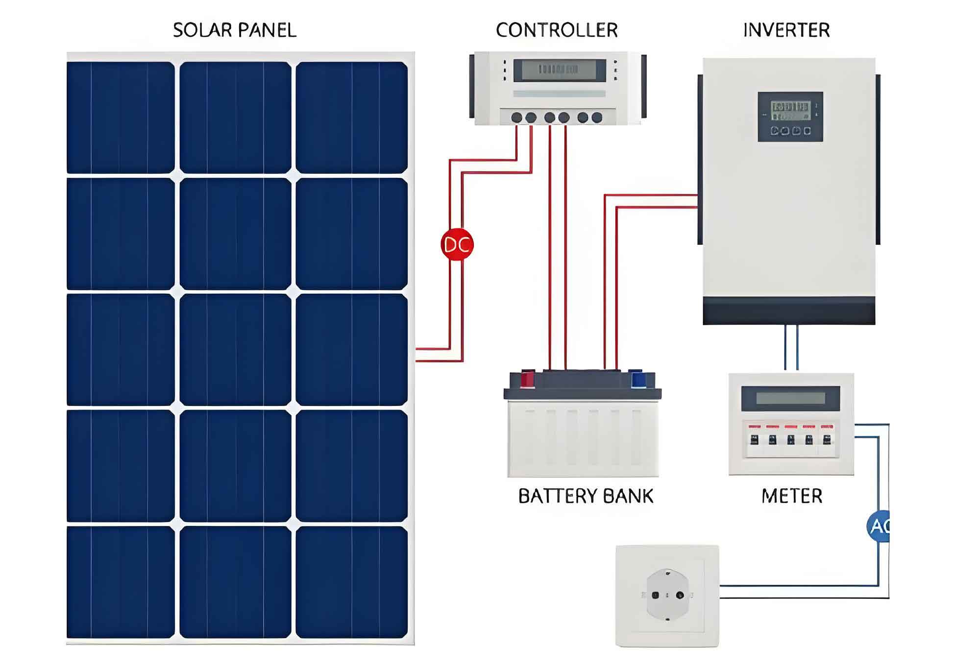
1. Fundamental Principles
For solar inverter-integrated energy storage systems, the insulation withstand voltage (IWV) represents the maximum potential difference a dielectric material can endure without breakdown. The critical relationship between altitude and dielectric strength is expressed as:
$$U_{GB} = \left[1 – \left(\frac{H}{100}\right) \times 0.01\right] \times U_{max}$$
Where $H$ denotes altitude (meters) and $U_{max}$ represents sea-level withstand voltage. This formula proves essential when designing battery systems for solar inverters operating in high-altitude environments.
2. Experimental Methodology
We conducted systematic evaluations using a 1500V battery system with the following test matrix:
| Test Type | Voltage Range | Duration | Evaluation Criteria |
|---|---|---|---|
| Insulation Resistance | DC 0-5 kV | 60s | ≥100 MΩ |
| Voltage Withstand | DC 0-8.8 kV | 60s | Leakage current <1mA |
The testing protocol included three critical scenarios:
- Battery module + BMU emulator
- Full system with operational BMU
- Module with disconnected cables
3. Key Findings
Our experiments revealed significant insights about solar inverter-compatible battery systems:
| Condition | Insulation (kV) | Withstand (kV) | BMU Status |
|---|---|---|---|
| Ideal wiring | >5.0 | >8.0 | Functional |
| 4mm air gap | 5.0 | 7.8 | Functional |
| Exposed tips | 3.0 | 7.2 | Damaged |
The dielectric breakdown threshold follows the empirical relationship:
$$V_{breakdown} = 3 \times d\ (\text{mm})$$
Where $d$ represents the critical clearance distance between conductors. For solar inverter applications requiring 1500V operation, this mandates minimum clearances of 5mm between live components.
4. Reliability Enhancement Strategies
Three primary improvements were validated for solar inverter-coupled systems:
- Structural Optimization: Maintain ≥4mm conductor-to-chassis clearance
- Process Refinement: Implement multi-layer insulation wrapping:
$$R_{ins} = R_{base} \times \prod_{i=1}^{n}(1 + k_i)$$
Where $k_i$ represents each insulation layer’s effectiveness factor (typically 0.2-0.5) - Material Upgrade: Utilize glass-fiber reinforced polymer (GFRP) brackets with:
$$\varepsilon_r = 4.2\ \text{(vs aluminum } \varepsilon_r = 1.0\text{)}$$
5. High-Altitude Adaptation
For solar inverters deployed at 4800m altitude, the modified withstand voltage requirement becomes:
$$U_{4800} = 8.0 \times \left[1 – \left(\frac{4800}{100}\right) \times 0.01\right] = 4.16\ \text{kV}$$
This confirms the system’s compliance with derated requirements through our enhanced design parameters.
6. Conclusion
This research establishes comprehensive guidelines for optimizing energy storage battery units in solar inverter applications. Key achievements include:
- 5.0kV insulation/8.8kV withstand capability verification
- Quantified altitude-derating methodology
- Practical design rules for cable management
The proposed enhancements enable reliable integration of battery storage with solar inverters, particularly in challenging environmental conditions. Future work will investigate dynamic insulation degradation patterns under real-world photovoltaic cycling conditions.