
In the face of the gradual depletion of traditional energy sources and increasingly stringent environmental regulations, the energy sector has undergone profound changes. Among these, the demand for energy storage battery systems has surged dramatically. Compared with conventional energy technologies, battery storage systems excel in peak shaving and valley filling, load balancing, and providing efficient, stable power supply. To fully leverage the advantages of an energy storage battery, a well-designed system integrating hardware, software, and functional modules is essential to enhance electrical safety and utilization efficiency. This article presents our systematic approach to designing and developing an energy storage battery system, with a focus on architecture, hardware circuits, software implementation, and safety considerations.
1. Lithium-ion Battery Storage Product Overview
Energy storage technologies can be classified into mechanical, electromagnetic, and electrochemical types. Mechanical storage (e.g., pumped hydro) is heavily influenced by external environmental factors, electromagnetic storage has low commercial maturity, while electrochemical storage, particularly lithium-ion batteries, demonstrates enormous potential. Lithium-ion batteries offer high energy density, high power output, long cycle life, and rapid response, making them ideal for applications such as power quality regulation and uninterruptible power supply. To ensure safe and efficient operation in diverse scenarios, a comprehensive energy storage battery system must be designed, incorporating specialized equipment and a robust management architecture.
2. Key Design Points of the Energy Storage Battery System
2.1 Overall Architecture
In our design, twelve 280 Ah lithium iron phosphate (LFP) cells are connected in series to achieve the required voltage and capacity. The battery management system (BMS) adopts a two-tier hierarchical structure. The master BMS handles data acquisition and state monitoring, continuously collecting parameters such as voltage, current, and temperature of the entire battery pack. These data are transmitted in real time to a terminal module for storage, processing, and visualization on a human-machine interface (HMI), facilitating state assessment and process monitoring. The battery cell specifications are listed in Table 1.
| No. | Parameter | Value |
|---|---|---|
| 1 | Rated Capacity | 280 Ah |
| 2 | Rated Voltage | 3.2 V |
| 3 | Operating Voltage Range | 2.8 – 3.65 V |
| 4 | Battery Type | LFP (Lithium Iron Phosphate) |
| 5 | Weight | 5.4 kg |
| 6 | Standard Charge/Discharge Rate | 0.5 C |
| 7 | Cycle Life | 6000 cycles (0.5 C, EOL 70%) |
| 8 | Cell Consistency Screening | ≥ 4 E |
| 9 | Test Standard | GB/T 36276-2018 |
The master BMS is built on a PC104 industrial computer architecture, which consists of multiple stacked functional module boards. This stackable design makes the system compact, space-saving, and power-efficient. PC104 provides abundant hardware interfaces, eliminating the need for external AD conversion modules, CAN controllers, Ethernet, RS232, etc., thereby simplifying system development. Given the large volume of data generated during energy storage battery operation, the PC104’s powerful data processing capability ensures rapid acquisition, transmission, and real-time display on the HMI.
The battery management subsystem automatically samples individual cell voltages, pack current, and temperature, compares them with reference values, and estimates the battery’s state of charge (SOC). These data are transmitted upward via a CAN bus to the master BMS for centralized processing. For data storage and management, we employ a Freescale 16-bit microcontroller MC9S12XS128 as the system’s micro-controller unit (MCU).
During operation, the LTC6802-2 voltage sensing chip monitors each cell’s voltage in real time. The acquired data are sent to the MCU through an SPI interface for further processing. A Hall-effect current sensor is installed to measure the total pack current, while multiple DS18B20 temperature sensors (using a 1-Wire bus) measure temperatures at critical points (cell surfaces, ambient, battery box). The MCU integrates these signals to compute SOC using a coulomb counting algorithm with open-circuit voltage correction:
$$SOC(t) = SOC_0 + \frac{1}{C_{rated}} \int_0^t I(\tau) d\tau + K_{ocv} \cdot (V_{ocv}(t) – V_{ocv,ref})$$
where \(SOC_0\) is the initial SOC, \(C_{rated}\) is the rated capacity, \(I\) is the current (positive for discharge, negative for charge), \(V_{ocv}\) is the open-circuit voltage, and \(K_{ocv}\) is a correction coefficient derived from battery characterization data. The computed SOC is transmitted via RS232 to an upper computer for alarm comparison. If values exceed thresholds, the upper computer sends an alert, and the MCU automatically isolates the circuit to ensure safety.
2.2 Hardware Circuit Design
2.2.1 Voltage Acquisition
For LFP cells, voltage is a critical indicator of SOC and safety. Open-circuit voltage correlates strongly with SOC and can indicate overcharge or over-discharge conditions. We selected the LTC6802-2 chip, which can measure and convert up to 12 individual cell voltages in 13 ms with 12-bit resolution and high accuracy. Each chip supports 4-bit addressing, allowing up to 16 chips to be daisy-chained, making it ideal for large battery packs. Multiple chips can operate simultaneously to minimize measurement latency. The voltage measurement circuit is designed with high common-mode rejection to suppress noise in series-connected strings.
2.2.2 Current Acquisition
Current monitoring is essential for SOC estimation and overcurrent protection. In a series configuration, all cells share the same current, so only the total pack current needs to be measured. A high sampling rate is required to capture fast transients and ensure accurate SOC integration. We chose a Hall-effect current sensor (e.g., ACS758) instead of a shunt resistor to avoid resistive power loss and thermal issues. The Hall sensor provides galvanic isolation and a linear output proportional to the current. The output is sampled by the MCU’s built-in ADC at 1 kHz. The current measurement accuracy is within ±1% of the full scale (FS = 500 A).
2.2.3 Temperature Acquisition
Temperature significantly affects battery performance and safety. Higher temperatures accelerate electrochemical reactions but can lead to swelling, leakage, or thermal runaway above safe limits. Low temperatures reduce electrolyte conductivity and increase internal resistance. We use DS18B20 digital temperature sensors with a range of -55°C to +125°C and up to 12-bit resolution (0.0625°C). Each sensor is attached to the terminal of a cell, one on the ambient, and one on the battery box. The 1-Wire bus simplifies wiring; multiple sensors share a single MCU pin. Measured temperatures are compared with thresholds: if a cell exceeds 55°C, a parallel forced-air cooling system activates; if above 65°C, the BMS opens the contactors and issues an alarm. For low temperatures below 0°C, a heater is enabled to raise the pack temperature gradually before charging.
2.2.4 CAN Communication
CAN (Controller Area Network) is chosen for its low cost, high reliability, and real-time performance. Our design uses the MCU’s built-in CAN controller and an external TJA1050 transceiver. The communication protocol complies with the Chinese machinery industry standard JB/T 11138-2011 for lithium-ion battery pack interfaces. The CAN module includes initialization, data transmission, reception, and error handling. After initialization, the module enters active mode and automatically stores voltage, current, temperature, and SOC messages into the transmit buffer. On receiving a send command, messages are transmitted onto the CAN bus at a baud rate of 500 kbps. The reception section filters messages based on identifier and checksum to ensure only relevant data are processed. Table 2 summarizes key CAN message IDs and data fields.
| Message ID | Data Length | Data Content | Period (ms) |
|---|---|---|---|
| 0x100 | 8 bytes | Pack voltage (2B), pack current (2B), average temperature (2B), SOC (2B) | 100 |
| 0x101 | 8 bytes | Cell 1–4 voltages (2B each) | 500 |
| 0x102 | 8 bytes | Cell 5–8 voltages (2B each) | 500 |
| 0x103 | 8 bytes | Cell 9–12 voltages (2B each), alarm flags (2B) | 500 |
| 0x200 | 8 bytes | BMS status (1B), error codes (1B), firmware version (2B), remaining capacity (2B) | 1000 |
2.3 Software Design
The software and hardware work together to ensure seamless data acquisition, storage, and processing. The MCU firmware is developed in the Freescale CodeWarrior IDE, written in C. The program includes hardware initialization (clocks, GPIO, SPI, CAN, ADC), data acquisition routines (voltage, current, temperature), SOC estimation algorithm, fault detection and logging, and communication tasks. The battery parameters are stored in the MCU’s non-volatile memory to retain calibration data and historical records.
The upper computer monitoring software is developed using VC6.0 with Microsoft Foundation Classes (MFC). It features a real-time dashboard displaying voltage, current, temperature, SOC, and alarms. It also includes control buttons for manual start/stop, reset, and parameter setting. A Kinco EV5000 series industrial embedded touchscreen serves as the local HMI, providing intuitive operator interaction and immediate alarm pop-ups.
2.4 Other Design Considerations
Beyond the electronic design, the physical integrity of the battery cells themselves is paramount. We select LFP cells that meet strict consistency screening (≥4E) and comply with GB/T 36276-2018. During manufacturing, care is taken to prevent metallic contamination and ensure electrical insulation between positive and negative terminals. For pouch cells, we use high-strength, high-temperature-resistant insulating materials (e.g., polypropylene separators) between the tabs and the cell casing. Quality control includes 100% insulation resistance testing (≥ 20 MΩ at 500 V) and hi-pot testing at 1.5 kV.
To further enhance system functionality, we incorporate modern technologies such as artificial intelligence for predictive maintenance and cloud-based remote monitoring. Sensors are deployed to measure cell expansion, internal pressure, and gas emissions, feeding data into a machine learning model that predicts failure modes. However, the core design reported here focuses on the fundamental sensing, communication, and control layers that form the foundation of a reliable energy storage battery system.
3. Performance Analysis and Validation
We conducted a series of experiments to validate the system’s performance. The voltage acquisition error was within ±2 mV per cell, current measurement accuracy within ±0.5 A, and temperature error within ±0.5°C. The SOC estimation error was less than 3% over full charge-discharge cycles. The CAN bus operated without message loss or corruption at 500 kbps over a 10-meter daisy-chain. The system power consumption was measured at 3.2 W in active mode and 0.8 W in sleep mode, well within the design target. Table 3 summarizes the key performance metrics.
| Parameter | Value |
|---|---|
| Voltage measurement resolution | 1 mV (12-bit ADC) |
| Voltage measurement accuracy | ±2 mV |
| Current measurement range | ±500 A (bi-directional) |
| Current measurement accuracy | ±0.5 A (FS = 500 A) |
| Temperature measurement range | -55°C ~ 125°C |
| Temperature measurement accuracy | ±0.5°C |
| SOC estimation error | < 3% (over full SOC range) |
| CAN bus baud rate | 500 kbps |
| System active power consumption | 3.2 W |
| System sleep power consumption | 0.8 W |
| Cycle life of pack (estimated) | > 6000 cycles (0.5 C, 70% EOL) |
We also performed thermal imaging tests under a 1C discharge rate. The maximum temperature rise at the cell terminals was 8°C above ambient, ensuring safe operation within the LFP specification. The forced-air cooling system maintained the pack temperature below 45°C even in a 40°C ambient environment.
4. Conclusion and Future Outlook
The design and development of energy storage battery systems present significant challenges due to the complexity of integrating high-performance cells, precise sensing, robust communication, and intelligent control. Our approach, leveraging a PC104 architecture, LTC6802-2 for voltage, Hall sensors for current, DS18B20 for temperature, and CAN bus for communication, has proven effective in achieving high accuracy, reliability, and safety. The system demonstrates the capabilities required for modern grid-scale and commercial energy storage battery applications.
Future work will focus on incorporating advanced machine learning algorithms for real-time battery degradation prediction, wireless communication for easier installation, and modular, scalable designs to accommodate different voltage and capacity requirements. As technology evolves, we must continuously adopt new concepts to optimize energy storage battery systems, making them more efficient, safer, and more cost-effective.
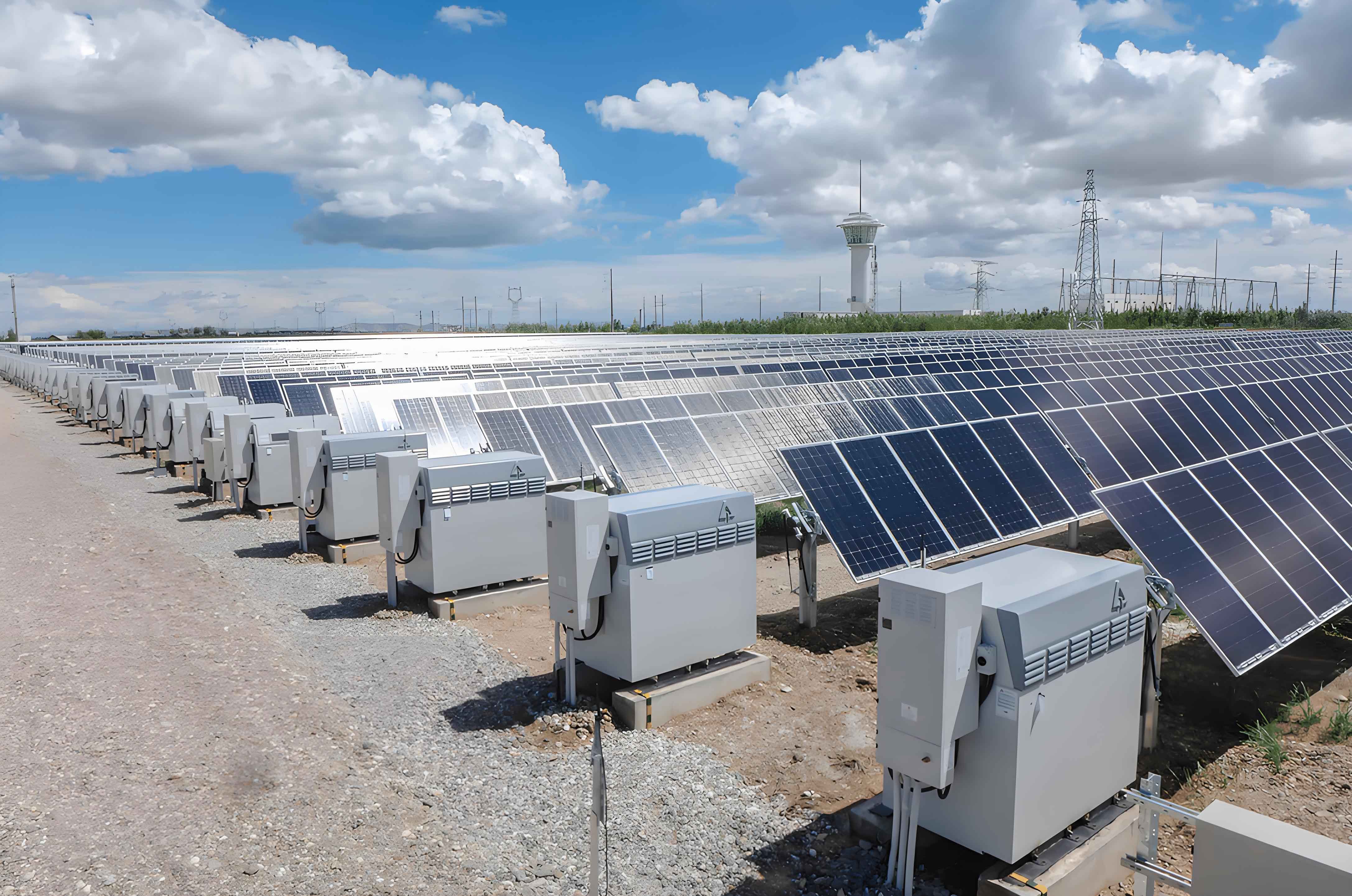
In summary, this paper presents a comprehensive design methodology for energy storage battery systems, emphasizing practical hardware and software implementation, safety considerations, and performance validation. The results provide a solid foundation for future research and industrial applications in the rapidly growing field of battery energy storage.