
Abstract: This article focuses on the mechanical performance of the down – stayed purlin structure with photovoltaic panels under fire. It begins with an introduction to the background of installing photovoltaic panels on light steel factory roofs and the need for research on the mechanical properties of the down – stayed purlin structure in case of fire. Then, through finite element modeling and analysis, including the establishment of the down – stayed purlin model, geometric model, fire source model, and determination of material properties and temperature rise calculations, the mechanical performance of the purlin structure under normal temperature and fire conditions is studied. The results show that under normal temperature, the down – stayed purlin structure can effectively improve the stiffness and bearing capacity of the purlin, while under fire conditions, it can still improve the stiffness, but the improvement of bearing capacity is limited. Therefore, passive fire protection measures such as applying fire – retardant coatings are recommended for the down – stayed purlin. This research provides a theoretical basis for the fire – resistant design of the down – stayed purlin structure with photovoltaic panels.

1. Introduction
1.1 Background
In recent years, with the increasing emphasis on clean energy, the installation of photovoltaic panels on the roofs of industrial and commercial buildings has become more and more common. For light steel factory buildings, the installation of photovoltaic panels can not only make full use of roof space to generate electricity, but also bring certain economic benefits. However, the addition of photovoltaic panels increases the dead load on the roof, which may lead to problems such as excessive deformation of the simply supported purlins and insufficient bearing capacity. In order to solve these problems, the down – stayed purlin structure has been proposed as a reinforcement method. However, in the event of a fire, the mechanical performance of the down – stayed purlin structure is still unclear, and it is necessary to conduct in – depth research.
1.2 Research Significance
The research on the mechanical performance of the down – stayed purlin structure with photovoltaic panels under fire is of great significance. Firstly, it can provide a theoretical basis for the design and reinforcement of light steel factory roofs with photovoltaic panels, ensuring the safety and reliability of the structure under normal and fire conditions. Secondly, it helps to optimize the design of the down – stayed purlin structure, improve its mechanical performance, and prolong the service life of the structure. Finally, it can also provide reference for the development of relevant fire protection standards and regulations, promoting the application and development of photovoltaic power generation technology in the field of light steel structures.
2. Finite Element Model
2.1 Down – Stayed Purlin
The roof purlins of light steel factory buildings are usually made of cold – formed thin – walled C – section steel. When the roof panel has sufficient stiffness and is firmly connected to the purlins, the overall stability of the purlins may not need to be checked, and the failure mode is usually considered as bending failure. To address this, a down – stayed purlin structure is proposed, which consists of two braces installed at the lower end of the purlin. The braces are supported by diagonal tension rods at both ends and a straight tension rod in the middle, and the tension rods are fixed at both ends of the purlin.
| Component | Section Size (mm) |
|---|---|
| Purlin | 160x70x20x3 |
| Brace | 25×1.5 |
| Tension Rod | 8 |
2.2 Geometric Model
In this study, the finite element software ANSYS WORKBENCH is used to establish the model. The down – stayed purlin structure is selected, with a purlin span of 6m, a space height of 20m, and a purlin spacing of 2m. Considering the actual engineering situation, the height of the brace is set to 0.5m, and the brace spacing is selected as 1/3 of the purlin span, which is 2m. The components are modeled using Beam elements, and the connections between the components are rigid joints. The support conditions are hinged at both ends of the purlin. During the finite element mesh generation, a general mesh division is adopted. The photovoltaic module used is the JAM60 285 – PR module, with a single – piece plane size of 1650mm x 991mm x 40mm and a weight of 0.13kN/m². According to the GB 50009 – 2012 “Load Code for the Design of Building Structures”, the dead load is taken as 0.5kN/m², the live load is taken as 0.5kN/m², and the wind load is not considered. In addition to the self – weight of the down – stayed purlin, the equivalent uniform linear load design value applied to the purlin is 2.26kN/m.
2.3 Fire Source Model
Since the main structures requiring the down – stayed purlin structure are mostly light steel factory buildings with a height of more than 10m and often adopt a portal frame or bent frame system, which belongs to a large space, the indoor temperature rise law does not conform to the standard temperature rise curve ISO834. In this study, the practical empirical formula for the air temperature rise in a large – space building fire obtained by Li Guoqiang is selected. The fire power is considered as 5MW, and the fire speed is medium. The formula is as follows:
T(m,h,t)-Ts(0)=
where T(m,h,t) is the air temperature (°C) at a horizontal distance from the fire source center and a vertical distance h(m) from the ground at time t; Ts(0) is the indoor initial temperature, which can be set as 20°C; Th is the maximum air temperature at a vertical distance h(m) from the ground to the fire source center (°C); δ is the temperature rise curve coefficient determined according to the fire power and growth rate; v is the distance between the outermost edge point of the fire source and the center point of the fire source (m); φ is the temperature attenuation coefficient (dimensionless), and when x<v , it is taken as 1.
In this study, the simulated fire source is located on the ground, and the center of the fire source coincides with the center of the purlin. Through the above calculation formula, the temperature field distribution of the down – stayed purlin structure during the heating process can be obtained. The temperature field distribution of the purlin after heating for 60 minutes.
2.4 Material Properties of Steel at High Temperature
The purlins and braces of the down – stayed purlin structure are made of Q235 ordinary steel, and the tension rods are made of HRB400 grade steel. According to the research of Li Guoqiang, the yield strength of Q235 ordinary steel at room temperature is 235MPa, the yield strength of HRB400 steel is 360MPa, and the elastic modulus is 206000MPa. The linear expansion coefficient of Q235 ordinary steel material at high temperature can be taken as 1.2 x 10⁻⁵; the density can be taken as 7850kg/m³, and the Poisson’s ratio can be taken as 0.3. The thermodynamic parameters of the steel at different temperatures are shown in Table 2. The constitutive relationship adopts an ideal elastoplastic model.
| Temperature () | Yield Strength (MPa) | Elastic Modulus (MPa) | Thermal Conductivity (W·m⁻¹·⁻¹) | Specific Heat Capacity (J·kg⁻¹·⁻¹) |
|---|---|---|---|---|
| 20 | 235 | 206340 | 53.3 | 439.8 |
| 50 | 235 | 206143 | 52.3 | 459.7 |
| 100 | 235 | 204245 | 50.7 | 487.6 |
| 150 | 235 | 201333 | 49.0 | 510.4 |
| 200 | 235 | 197900 | 47.3 | 529.8 |
| 250 | 235 | 193910 | 45.7 | 547.3 |
| 300 | 235 | 188795 | 44.0 | 564.7 |
2.5 Temperature Rise Calculation of Steel Members
The heat transfer between the ambient air and the steel members mainly occurs through heat radiation and heat convection, and there is also heat conduction inside the steel members due to the temperature difference. The temperature rise calculation formula of the steel members given by the European code EC.3, which has a more conservative calculation result, is adopted as follows:
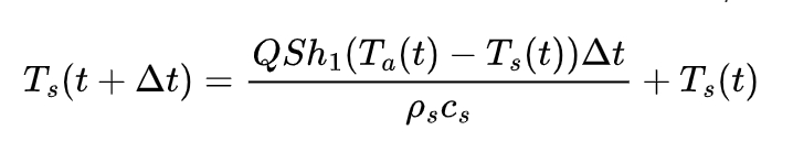
where Q is the correction coefficient considering the influence of the fire smoke shadow, taken as 1.0; S is the surface coefficient of the steel member, which is equal to the ratio of the surface area and volume of the steel member; h1 is the design value of the net heat flux per unit area; Ta(t) is the air temperature near the steel member at time t; Ts(t) is the temperature of the steel member at time t, and when t=0, it is taken as 20°C; to ensure the accuracy of the incremental calculation, does not exceed 5s.
The improved calculation formula for the design value of the net heat flux h1 per unit area given by Zheng Yongqian is adopted as follows:
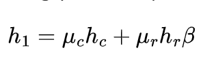
where μc and μr are safety coefficients, taken as 1.0 and 0.15 respectively; hc is the heat flow transferred in the form of heat convection, and its value is hc=bc(Tα-Ts); bc is the convective heat transfer coefficient, taken as 25W/m²·. The heat flow hr transferred in the form of heat radiation can be calculated as follows:
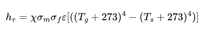
where x is the shape coefficient, taken as 1.0; σm is the radiation coefficient related to the surface shape of the steel member, and for the unprotected steel member surface, it is taken as 0.3; σf is the radiation coefficient related to the fire room, usually taken as 0.8; ε is the blackbody radiation constant, with a value of 5.67 x 10⁻⁸W·m⁻²·K⁻⁴.
3. Mechanical Performance Analysis of Purlin under Normal Temperature
3.1 Mechanical Performance Analysis of Simply Supported Purlin under Normal Temperature
According to the provisions in the “Design Standard for Steel Structures” in China, the maximum deflection value of the roof purlin under the standard value of the load should not exceed ( is the purlin span value). In this model, the purlin span is 6m, so the allowable maximum deflection value is 40mm. The displacement and stress distribution of the simply supported purlin under normal temperature.
From the displacement situation of the roof purlin, it can be seen that under the action of the vertical load at normal temperature, the displacement in the middle of the simply supported purlin span is the largest, with a maximum displacement of 48.59mm, which has exceeded the allowable maximum deflection value of the purlin. Therefore, the deformation of the simply supported purlin after the installation of the photovoltaic panel does not meet the requirements at normal temperature. From the stress situation of the simply supported purlin, it can be seen that under the action of the vertical load at normal temperature, the stress at the purlin support is greater than that in the middle span region, with a maximum stress of 119.03MPa, which does not exceed the yield strength of 235MPa at normal temperature, so the member will not yield. This indicates that the deformation of the simply supported purlin is the key factor affecting the safety of the purlin at normal temperature.
3.2 Mechanical Performance Analysis of Down – Stayed Purlin under Normal Temperature
When the simply supported purlin has a large deformation that is not suitable for further bearing, the down – stayed purlin can be used to improve the stiffness and bearing capacity. The displacement and stress distribution of the down – stayed purlin under normal temperature.
From the displacement situation of the down-stayed purlin, it can be seen that under the action of the vertical load at normal temperature, the displacement of the tension rod is the largest, with a maximum displacement of 37.12mm; the displacement of the purlin is reduced, and the maximum displacement in the middle span region of the purlin is 14.50mm, which does not exceed the allowable maximum deflection value of the purlin, indicating that the reinforcement with the down – stayed purlin can effectively improve the stiffness of the purlin. From the stress situation of the down – stayed purlin , it can be seen that under the action of the vertical load at normal temperature, the stress at the support of the down – stayed purlin is greater than that in the middle span region, with a maximum stress of 98.27MPa, which does not exceed the yield strength of 235MPa at normal temperature and is lower than the maximum stress generated by the simply supported purlin at normal temperature, indicating that the reinforcement with the down – stayed purlin can effectively improve the bearing capacity of the purlin.
4. Mechanical Performance Analysis of Purlin under Fire
4.1 Mechanical Performance Analysis of Simply Supported Purlin under Fire
The fire resistance of the steel structure is relatively poor, and generally, the roof purlin is not passively fire – protected. Therefore, it is necessary to analyze the mechanical performance of the roof purlin under fire. The displacement and stress of the simply supported purlin under fire continue to increase, and the stress reaches the maximum at 1800s. The displacement and stress distribution of the simply supported purlin at 1800s under fire.
From the displacement situation of the simply supported purlin, it can be seen that under the action of the vertical load under fire, the displacement response of the roof purlin continues to increase, and the displacement in the middle span region is the largest. At 1800s, the maximum displacement reaches 53.61mm, exceeding the allowable maximum deflection value of the purlin. From the stress situation of the simply supported purlin, it can be seen that under the action of the vertical load under fire, the stress at the support of the purlin is greater than that in the middle span region. The maximum stress reaches the yield strength of 235MPa at 1300s, and then the local stress of the purlin slightly increases, with a maximum of 248.02MPa, and the purlin fails.
4.2 Mechanical Performance Analysis of Down – Stayed Purlin under Fire
From the displacement situation of the down – stayed purlin, it can be seen that under the action of the vertical load under fire, the displacement of the tension rod of the down – stayed purlin increases rapidly, with a maximum displacement of 122.94mm at 1800s, while the displacement of the purlin increases slowly, with a maximum of only 37.70mm, which does not exceed the allowable maximum deflection value of the purlin, indicating that the reinforcement with the down – stayed purlin can still effectively improve the stiffness of the purlin under fire. From the stress situation of the down – stayed purlin , it can be seen that under the action of the vertical load under fire, the stress at the support of the purlin is greater than that in the middle span region. The maximum stress reaches the yield strength of 235MPa at 1500s, which is 200s later than that of the simply supported purlin. Then, the local stress of the purlin slightly increases, reaching the maximum at 1800s, with a maximum stress of 242.76MPa, and the purlin fails. This indicates that the reinforcement with the down – stayed purlin under fire cannot effectively improve the bearing capacity of the purlin. Through comprehensive analysis of the displacement and stress responses, it can be concluded that the reinforcement with the down – stayed purlin under fire can effectively improve the stiffness of the purlin, but the improvement of the bearing capacity is limited.
5. Conclusion
5.1 Summary of Research Results
Under normal temperature, the addition of the roof panel will cause the simply supported purlin to have large deformations that are not suitable for continued loading. However, by adopting the down – stayed purlin structure for reinforcement, the stiffness and bearing capacity of the purlin can be effectively enhanced. The maximum displacement of the simply supported purlin under normal temperature exceeds the allowable limit, while that of the down – stayed purlin is within the acceptable range, and the maximum stress of the down – stayed purlin is also lower than that of the simply supported purlin.
Under fire conditions, the displacement of the simply supported purlin increases rapidly and exceeds the allowable maximum deflection value. In contrast, the displacement development of the down – stayed purlin is relatively slow, indicating that the down – stayed purlin can still effectively improve the stiffness of the purlin under fire. Nevertheless, although the down – stayed purlin can delay the time when the maximum stress reaches the yield strength compared to the simply supported purlin, its ability to improve the bearing capacity is limited.
5.2 Recommendations for Engineering Applications
Based on the research results, for light steel factory roofs reinforced with down – stayed purlins and equipped with photovoltaic panels, passive fire protection measures should be implemented for the down – stayed purlins. For example, applying fire – retardant coatings can effectively enhance the fire resistance of the purlins and ensure that they can maintain better mechanical performance in the event of a fire, thereby improving the overall fire safety of the structure.
In future engineering designs, the influence of photovoltaic panel installation on the mechanical performance of the roof structure should be fully considered. Appropriate reinforcement and fire protection measures should be selected according to the actual situation to ensure the safety and durability of the structure. At the same time, further research can be carried out to explore more efficient and economical reinforcement and fire protection methods to meet the development needs of the construction industry.
In conclusion, this research provides a theoretical basis and practical guidance for the application and fire protection design of down – stayed purlin structures with photovoltaic panels in light steel factory buildings. It helps to promote the healthy development of the integration of solar energy utilization and light steel structure construction.