
In my extensive work on energy storage technologies, I have focused on developing a robust and efficient battery management system (BMS) specifically for LiFePO4 energy storage applications. The growing integration of renewable energy sources like wind and solar power into the grid has highlighted the critical need for reliable energy storage solutions. LiFePO4 batteries, with their high safety, long cycle life, and environmental friendliness, have emerged as a prime candidate for large-scale energy storage. However, managing these batteries effectively requires a sophisticated system that can monitor, control, and optimize their performance. This article details my comprehensive design of a BMS for LiFePO4 energy storage, covering overall architecture, hardware and software implementations, and advanced state-of-charge (SOC) estimation techniques. Throughout this discussion, I will emphasize the unique challenges and solutions associated with LiFePO4 battery technology.
The core objective of my design was to create a BMS that ensures the safety, longevity, and efficiency of LiFePO4 battery packs in stationary energy storage systems. Such systems often involve hundreds or thousands of individual cells, making centralized management impractical. Therefore, I adopted a modular, two-tiered architecture. The top tier, or master BMS, is responsible for system-wide coordination, communication with external systems like power conversion systems (PCS), and high-level data processing. It is built around a PC104 industrial computer module. The PC104 platform offers a compact, stackable form factor, low power consumption, and rich built-in peripherals like Ethernet, multiple serial ports, and analog-to-digital conversion capabilities. This eliminates the need for designing numerous external circuits, thereby enhancing reliability and reducing complexity. The master BMS collects aggregate data (total pack voltage, current) and receives detailed information from the lower tier.
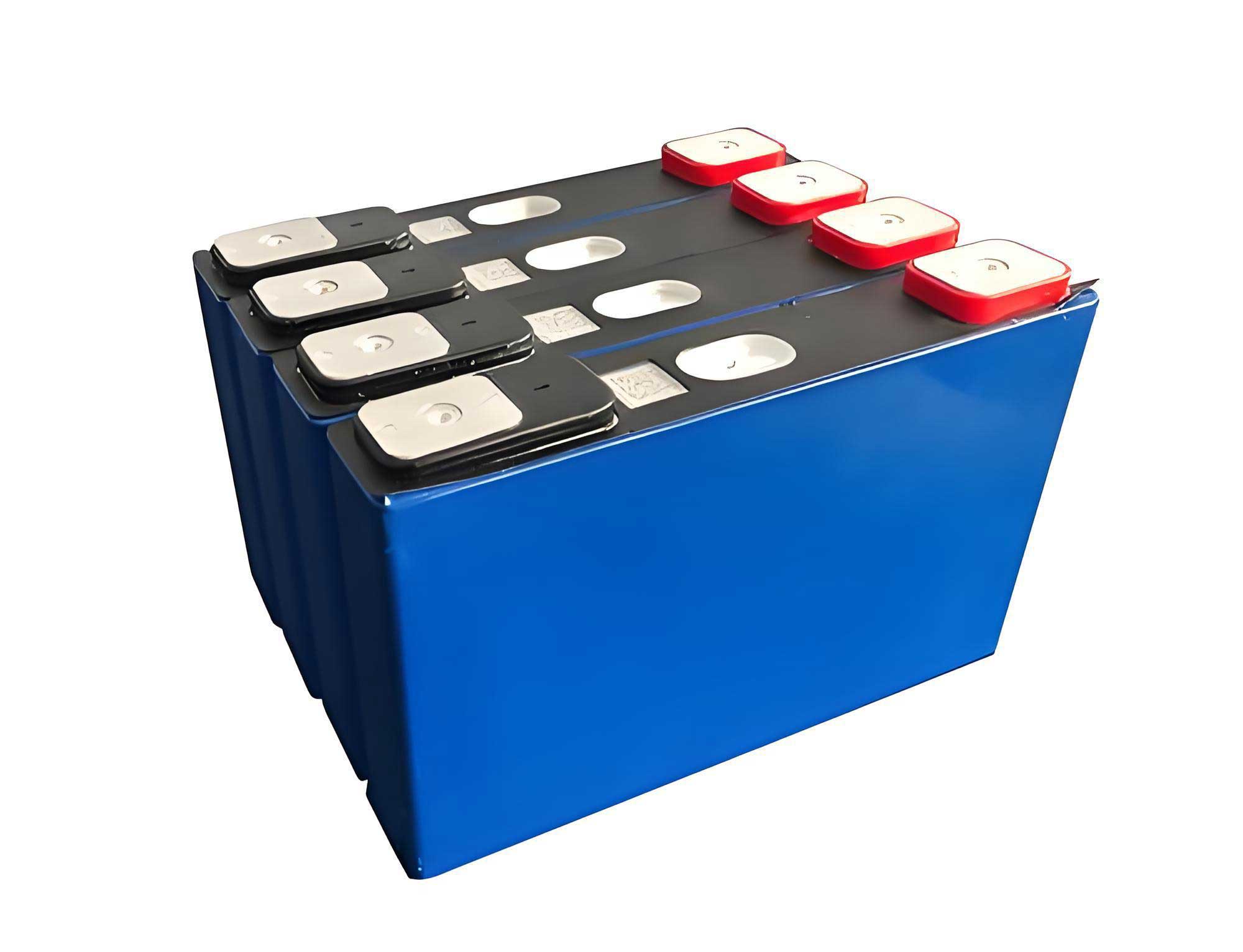
The lower tier consists of multiple slave BMS units, each dedicated to monitoring a module of series-connected LiFePO4 batteries. In my design, each module comprises 12 individual 180 Ah LiFePO4 cells. Each slave unit is centered around a Freescale MC9S12XS128 16-bit microcontroller (MCU). This MCU was chosen for its integrated features, including a Controller Area Network (CAN) controller, Serial Peripheral Interface (SPI), Analog-to-Digital Converter (ADC), and serial communication interfaces, which are essential for this application. The slave BMS performs real-time monitoring of individual cell voltages, module current, temperature at various points, and estimates the SOC for its assigned module. All data is transmitted to the master BMS via a high-integrity CAN bus network. The overall system structure ensures scalable, distributed management suitable for large LiFePO4 energy storage installations.
Accurate voltage measurement is paramount for the health and safety of any LiFePO4 battery system. The open-circuit voltage of a LiFePO4 cell correlates closely with its state of charge and can indicate potential faults like overcharge or over-discharge. For my design, I selected the Linear Technology LTC6802-2 integrated circuit as the cornerstone of the voltage acquisition subsystem. This chip is exceptionally well-suited for monitoring series-connected LiFePO4 battery stacks. A single LTC6802-2 can measure the voltage of up to 12 cells connected in series, with a maximum stack voltage of 60V. Its measurement accuracy is 0.25%, and it can complete a full scan of all 12 cells in just 13 milliseconds. The device includes a built-in 12-bit ADC, a precision voltage reference, and an SPI interface for communication with the MCU.
To manage larger packs, multiple LTC6802-2 devices can be daisy-chained. Each chip has a configurable 4-bit address, allowing up to 16 devices (monitoring 192 cells) to be connected on a single SPI bus. They operate in a synchronous fashion, enabling simultaneous voltage sampling across all cells in the system, which is crucial for precise SOC calculation and cell balancing decisions. The connection scheme for the first LTC6802-2 in a chain involves connecting its voltage input pins (V1 to V12) across the respective LiFePO4 cells. Isolation and level shifting are inherently managed by the chip’s design. The SPI interface connects directly to the MCU, streamlining the hardware design significantly compared to discrete multiplexer and ADC solutions. This approach minimizes board space, power consumption, and potential points of failure, which is vital for maintaining the reliability of a LiFePO4 energy storage BMS.
Current monitoring is equally critical, as it directly feeds into the coulomb counting method for SOC estimation and is essential for detecting overload conditions. In a series-connected LiFePO4 battery module, the current is uniform, so only one high-fidelity measurement point is required per module. I rejected the use of shunt resistors due to their inherent power loss (I²R heating) and the need for isolation circuitry. Instead, I incorporated a Hall-effect based current sensor. These sensors provide galvanic isolation and produce a linear voltage output proportional to the measured current. The specific sensor used in my design has a measurement range suitable for the module’s operational current, with an output voltage swing of -5V to +5V and an accuracy of ±0.5%.
The analog voltage output from the Hall sensor is fed into one of the MCU’s 12-bit ADC channels. A high sampling rate is maintained to capture dynamic current changes accurately, which is important for both precise SOC tracking and safety protection. The relationship between the ADC reading and the actual current is given by a linear calibration formula. If $V_{adc}$ is the ADC reading (in volts after scaling from the digital value), $V_{offset}$ is the zero-current output voltage (typically 2.5V for a bipolar sensor centered at 0A), and $S$ is the sensor sensitivity (in V/A), then the battery current $I_{bat}$ can be calculated as:
$$ I_{bat} = \frac{V_{adc} – V_{offset}}{S} $$
This current value, sampled frequently, forms the basis for the ampere-hour integration performed by the SOC estimation algorithm.
Temperature profoundly affects the performance, safety, and aging of LiFePO4 batteries. High temperatures can accelerate degradation and pose thermal runaway risks, while low temperatures drastically reduce available capacity and increase internal resistance. Therefore, my BMS incorporates a comprehensive temperature monitoring scheme. I measure temperatures at multiple critical points: the surface of selected LiFePO4 cells, within the battery module enclosure, and the ambient environment. For this purpose, I chose the DS18B20 digital temperature sensor. This device communicates over a single-wire bus, allowing many sensors to be connected to a single MCU GPIO pin with minimal wiring. It offers a resolution up to 12 bits (0.0625°C) over a range of -55°C to +125°C, with an accuracy of ±0.5°C.
The single-wire protocol, while software-intensive, enables scalable and cost-effective temperature monitoring across a large LiFePO4 battery bank. Each DS18B20 has a unique 64-bit ROM code, allowing the MCU to address them individually. The temperature readings are used for several purposes: compensating the SOC estimation algorithm, triggering active thermal management systems (like fans for cooling or heaters for warming), and initiating safety alarms or disconnection commands if temperature limits are exceeded. The following table summarizes the key parameters and purposes of the three primary sensing subsystems in my LiFePO4 BMS design:
| Sensed Parameter | Primary Device | Key Specification | Purpose in BMS |
|---|---|---|---|
| Cell Voltage | LTC6802-2 IC | 12-bit ADC, 0.25% accuracy, 13ms for 12 cells | SOC estimation, Over-voltage/Under-voltage protection, Cell balancing |
| Module Current | Hall-effect Sensor | ±0.5% accuracy, -5V to +5V output, Isolated | SOC estimation (Coulomb counting), Over-current protection, Power calculation |
| Temperature | DS18B20 Sensor | 12-bit resolution, ±0.5°C accuracy, Single-wire bus | SOC compensation, Thermal management control, Safety alarm for over/under temperature |
Reliable and robust communication is the backbone of the distributed BMS architecture. For communication between the slave units and the master, I implemented the Controller Area Network (CAN) bus. CAN is an ideal choice for industrial and automotive applications due to its noise immunity, priority-based arbitration, and error detection capabilities. The MC9S12XS128 MCU has an integrated CAN controller (MSCAN). I interfaced this with a Philips TJA1050 CAN transceiver chip to meet the physical layer requirements. The communication protocol follows a standardized frame format to ensure interoperability. For the LiFePO4 battery system, I structured the data frames to include essential information. A typical data frame from a slave BMS might include fields for module ID, individual cell voltages (12 values), module current, temperatures, estimated SOC, and status flags (e.g., alarm conditions).
The CAN bus initialization involves setting the appropriate baud rate (e.g., 500 kbps for a good balance of speed and reliability), configuring acceptance filters for message identifiers, and setting the operation mode. The software on the slave MCU periodically packs the acquired data into CAN message buffers and requests transmission. The master PC104, equipped with a CAN interface card, receives these messages, unpacks them, and integrates the data into its global database. This setup allows for real-time monitoring and control of the entire LiFePO4 energy storage array. The use of a standardized bus like CAN also facilitates future expansion or integration with other system components, such as the grid-tie inverter or energy management system.
For local debugging and configuration, each slave BMS also features an RS-232 serial port interface, connected via the MCU’s SCI module. This port allows direct connection to a laptop for firmware updates, calibration, or real-time data logging during development and maintenance. The master BMS, being a PC104 system, offers multiple communication pathways: Ethernet for connecting to a central monitoring server or SCADA system, and additional serial ports for interfacing with a local human-machine interface (HMI) touchscreen display. This multi-layered communication strategy ensures comprehensive connectivity for the LiFePO4 battery management system.
The software design is partitioned between the slave MCU and the master PC104. On the slave MCU, the firmware is developed using the CodeWarrior IDE. The program is structured in a modular fashion, with clear separation of tasks. The main loop typically involves:
- Initialization: Configuring the MCU’s clocks, SPI for LTC6802-2, ADC for current sensing, timers for periodic tasks, CAN controller, and SCI port.
- Data Acquisition Task: Triggering the LTC6802-2 to perform a voltage scan, reading the Hall sensor via ADC, querying all DS18B20 temperature sensors on the one-wire bus.
- Data Processing Task: Converting raw readings to engineering units, running the SOC estimation algorithm, checking values against pre-defined alarm thresholds (e.g., cell voltage > 3.65V or < 2.5V, temperature > 50°C).
- Communication Task: Packaging processed data into CAN frames and transmitting them. Listening for commands from the master on the CAN bus.
- Safety & Control Task: If any alarm threshold is breached, setting status flags and, if configured for autonomous action, controlling hardware switches (like contactors or MOSFETs) via digital outputs to disconnect the LiFePO4 battery module from the load or charger.
A simplified software flowchart for the slave MCU is represented by the following sequence, though actual code is event-driven with interrupts:
$$ \text{Start} \rightarrow \text{Init Hardware} \rightarrow \text{Enter Main Loop} \rightarrow \text{Acquire V, I, T} \rightarrow \text{Calculate SOC} \rightarrow \text{Check Limits} \rightarrow \text{Pack CAN Data} \rightarrow \text{Transmit} \rightarrow \text{Repeat} $$
The master BMS software runs on the PC104’s operating system (typically a real-time OS or lightweight Linux). I developed this software using a combination of C/C++ for data processing and a higher-level language for the GUI. Its primary functions include:
- Aggregating data from all slave units via CAN.
- Maintaining a real-time database of the entire LiFePO4 bank’s status.
- Calculating overall pack SOC and state of health (SOH).
- Providing a graphical user interface (GUI) for system operators, displaying trends, alarms, and key parameters.
- Logging historical data for analysis and warranty purposes.
- Communicating with external systems via Modbus TCP/IP over Ethernet or other protocols to integrate with the broader energy management system.
For on-site visualization, I also designed an HMI screen using a dedicated HMI development tool (like eView’s EV5000). This screen runs on an industrial touch panel connected to the master BMS. It provides a simplified, robust interface showing real-time voltages, currents, temperatures, SOC of each LiFePO4 module, and system status, which is crucial for field technicians.
Perhaps the most algorithmically challenging aspect of the BMS for LiFePO4 batteries is accurately estimating the State of Charge (SOC). SOC is defined as the ratio of remaining charge to the battery’s maximum charge capacity, often expressed as a percentage. An inaccurate SOC can lead to inefficient use, over-discharge, or overcharge, all of which harm the LiFePO4 battery’s lifespan. The relatively flat discharge voltage profile of LiFePO4 chemistry makes voltage-based SOC estimation difficult during the middle range of discharge. Therefore, I employed a hybrid method that combines the coulomb counting (ampere-hour integration) method with open-circuit voltage (OCV) calibration.
The coulomb counting method is fundamental. If the initial SOC at time $t_0$ is $SOC(t_0)$, the current $I(t)$ is measured (positive for discharge, negative for charge), and $C_n$ is the nominal capacity of the LiFePO4 battery (e.g., 180 Ah), then the SOC at time $t$ is given by:
$$ SOC(t) = SOC(t_0) – \frac{1}{C_n} \int_{t_0}^{t} \frac{I(\tau)}{\eta(\tau)} d\tau $$
Here, $\eta(\tau)$ is the coulombic efficiency factor, which is very close to 1 for LiFePO4 batteries but can be adjusted for temperature and rate effects. The integral represents the net charge removed from or added to the battery. However, this method suffers from error accumulation due to sensor inaccuracies, uncertainty in initial SOC, and unknown capacity fade over time.
To mitigate these errors, I use the open-circuit voltage method for periodic recalibration. When the LiFePO4 battery is at rest (no current for a sufficiently long period, typically several hours), its terminal voltage relaxes to an OCV that has a more defined relationship with SOC, particularly at the high and low ends of the SOC range. By using a pre-characterized OCV-SOC lookup table for the specific LiFePO4 cells, the BMS can correct the SOC estimated by coulomb counting. The correction is applied when the battery is idle, or during the charge/discharge phases where the OCV-SOC curve is sufficiently steep and reliable. This hybrid approach significantly improves the long-term accuracy of SOC estimation for the LiFePO4 energy storage system.
The OCV-SOC relationship can be modeled by a polynomial or a piecewise linear function. For example, for a certain LiFePO4 cell, the OCV ($V_{oc}$) between 20% and 90% SOC might be approximated by:
$$ V_{oc}(SOC) = a_0 + a_1 \cdot SOC + a_2 \cdot SOC^2 + a_3 \cdot SOC^3 $$
where $a_0, a_1, a_2, a_3$ are coefficients determined empirically. The BMS firmware inverts this relationship (numerically) to find SOC when a reliable OCV is available.
Furthermore, temperature compensation is integrated. The effective capacity $C_{eff}$ of a LiFePO4 battery varies with temperature $T$. A simple model might be:
$$ C_{eff}(T) = C_n \cdot [1 + \alpha (T – T_{ref})] $$
where $T_{ref}$ is a reference temperature (e.g., 25°C) and $\alpha$ is a temperature coefficient (typically negative for low temperatures). This adjusted capacity is used in the coulomb counting integral. The table below outlines the key equations and their roles in the hybrid SOC algorithm for the LiFePO4 BMS:
| Method | Mathematical Expression | Role in Hybrid Algorithm | Conditions for Use |
|---|---|---|---|
| Coulomb Counting | $ SOC_{cc}(t) = SOC(t_0) – \frac{1}{C_n} \int_{t_0}^{t} I(\tau) d\tau $ (simplified, η≈1) | Primary, continuous SOC tracking during operation. | Always active when current is flowing. |
| OCV Calibration | $ SOC_{ocv} = f^{-1}(V_{oc}) $ from lookup table. | Periodic correction of $SOC(t_0)$ in the coulomb counting equation. | Applied when battery is at rest (I=0 for extended period) or at charge/discharge endpoints. |
| Temperature Compensation | $ C_{n,adj} = C_n \cdot f(T) $ | Adjusts the nominal capacity used in coulomb counting based on temperature. | Continuously applied based on measured temperature. |
In addition to core monitoring and SOC estimation, a complete BMS for LiFePO4 energy storage must include safety protection and cell balancing. My design incorporates hardware and software mechanisms to disconnect the battery pack via contactors or solid-state relays in case of severe over-voltage, under-voltage, over-current, or over-temperature events. Cell balancing is crucial to maintain uniformity among the series-connected LiFePO4 cells, which maximizes pack capacity and life. I implemented passive balancing (also called resistor bleeding) using the LTC6802-2’s integrated balancing MOSFET drivers. During charging, if any cell’s voltage exceeds a preset threshold (indicating it is becoming full before others), the BMS activates the corresponding MOSFET to shunt current through a resistor, dissipating excess energy as heat and allowing other cells to catch up. The balancing current is typically set at a few hundred milliamps. The decision to balance is based on voltage differences measured by the LTC6802-2.
Testing and validation of the designed LiFePO4 BMS were conducted using a prototype setup with actual 180 Ah LiFePO4 cells. The system successfully monitored all parameters in real-time, communicated data reliably over CAN to the master station, and estimated SOC with an error margin within 5% under dynamic load profiles simulating renewable energy storage cycles (charge from solar during the day, discharge to grid during peak evening hours). The graphical interfaces on both the PC104 master and the HMI touchscreen provided clear visibility into the system’s status. The use of the PC104 platform proved advantageous for rapid development of the master system’s data logging and network communication functions.
In conclusion, the battery management system I designed for LiFePO4 energy storage applications addresses the critical needs of safety, accuracy, and scalability. By leveraging a two-tier distributed architecture with robust hardware components like the LTC6802-2 for voltage sensing and the MC9S12XS128 for local control, and by implementing a sophisticated hybrid SOC estimation algorithm, the system ensures optimal performance and longevity of the LiFePO4 battery bank. The integration of CAN bus communication and multiple user interfaces allows for seamless operation within larger smart grid or microgrid infrastructures. As the demand for efficient energy storage grows, such advanced BMS designs will be indispensable for unlocking the full potential of LiFePO4 battery technology in stabilizing renewable energy sources and enhancing grid reliability. Future work could focus on integrating more advanced SOC and SOH algorithms using machine learning techniques, as well as implementing active cell balancing for higher efficiency in large-scale LiFePO4 energy storage systems.