
In the face of a persistent global energy crisis, the depletion of non-renewable resources and the environmental pollution from traditional fuels are driving forces for change. For a nation with escalating energy demands, the imperative under the “Dual Carbon” goals is clear: embrace new energy solutions. The transportation sector, particularly the shift from internal combustion engines to electric vehicles (EVs), represents a critical frontier. However, the widespread adoption of EVs brings its own challenge—increasing the load on the conventional power grid, which itself may still rely heavily on fossil fuels. This is where the integration of solar energy into charging infrastructure presents a compelling, sustainable pathway. A well-designed solar photovoltaic charging pile not only reduces grid dependency and transmission losses but also minimizes the carbon footprint of electric mobility. Therefore, a deep, technical analysis of the design of such a solar-integrated system is of paramount practical significance. This article delves into the architecture, key components, and control strategies essential for building a robust and efficient solar-powered charging station.
The necessity for developing solar-powered charging infrastructure stems from the evolving landscape of EV adoption. Charging demand is no longer confined to urban centers; it extends to highways, towns, and remote areas. Supplying this distributed demand solely via the traditional grid exacerbates transmission losses and conflicts with low-carbon development objectives. A decentralized solar system offers a synergistic solution. The solar resource potential across many regions is substantial. Harnessing this energy locally for EV charging alleviates grid pressure, reduces reliance on fossil-fuel-based generation, and significantly cuts down on environmental pollution. The core vision is to create a charging point that leverages a clean, onsite solar system, contributing directly to a greener transportation ecosystem.
Overall System Architecture and Design Philosophy
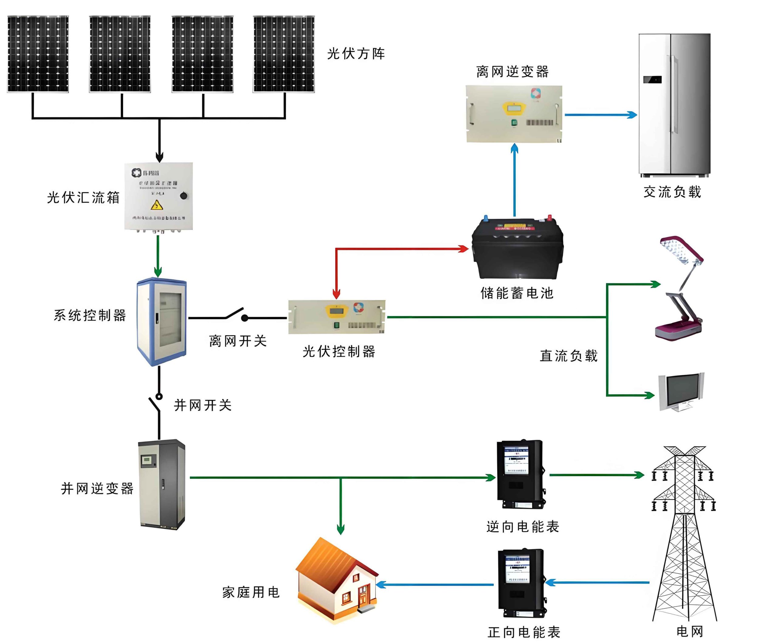
The fundamental design objective for a solar photovoltaic charging pile is to ensure reliable, stable, and efficient power delivery to EVs by intelligently integrating two power sources: the onsite solar generation system and the utility grid. The system must be user-friendly, safe, and capable of intelligent energy management. The operational principle revolves around prioritizing the use of solar energy. Photovoltaic (PV) panels convert sunlight into direct current (DC) electricity. This DC power is conditioned and can be used directly to charge an EV’s battery, stored in a local battery energy storage system (BESS), or fed back into the grid. When the solar system’s output is insufficient (e.g., at night or during cloudy weather), the system seamlessly draws power from the grid to maintain uninterrupted charging service. This dual-source approach guarantees reliability while maximizing the use of renewable energy.
The primary components of this integrated solar system include:
- Photovoltaic Generation Unit: Comprising PV panels, mounting structures, and DC cabling.
- Power Conversion Unit: This includes Maximum Power Point Tracking (MPPT) charge controllers and bidirectional inverters that manage the flow of power between DC (solar, batteries) and AC (grid, charger).
- Energy Storage Module (Battery): A bank of batteries for storing excess solar energy for later use, stabilizing the system, and providing backup power.
- Charging Unit (EVSE – Electric Vehicle Supply Equipment): The actual charging post with its power electronics, connectors, and control circuitry.
- Control & Management System: The brain of the operation, handling system protection, energy dispatch, user interaction, and data communication.
Key functional requirements for the charging pile include electrical protection (over-current, over-voltage, leakage), background management and monitoring, accurate energy metering, and an intuitive human-machine interface (HMI). Site selection is crucial: locations should have high solar irradiance, proximity to the grid connection point, and be situated along major EV traffic routes for accessibility.
Mitigating Grid Harmonics: The Role of the Active Power Filter (APF) System
Power electronic converters, which are ubiquitous in both EV chargers and PV inverters, are notorious for drawing non-linear currents from the grid. These currents introduce harmonic distortion—a form of electrical pollution that can cause overheating of transformers and cables, malfunction of sensitive equipment, and reduced power quality. To ensure that our solar charging pile is a good grid citizen and does not exacerbate these issues, integrating an Active Power Filter (APF) is essential. This section details the design and simulation of a shunt APF for this application.
Filtering Technology Selection
The two main harmonic mitigation techniques are Passive Power Filters (PPF) and Active Power Filters (APF). PPFs use combinations of inductors (L), capacitors (C), and resistors (R) tuned to specific harmonic frequencies. While low-cost, they are bulky, have fixed compensation characteristics, and can cause resonance problems with the grid impedance. In contrast, an APF is a power electronic system that injects compensating currents equal in magnitude but opposite in phase to the harmonic currents drawn by the load, thereby canceling them out. APFs are adaptive, can compensate for multiple harmonics and reactive power simultaneously, and do not interact adversely with the grid. Given the highly dynamic and non-linear nature of EV charging loads, the adaptive capability of an APF makes it the superior choice, despite its higher initial cost. APFs can be configured in series or shunt. Since the primary concern with charging piles is current harmonic distortion, a shunt-connected APF is the appropriate configuration.
Operational Principle and System Integration
The shunt APF is connected in parallel at the Point of Common Coupling (PCC)—the point where the charging pile connects to the grid. When an EV is plugged in and charging commences, the APF is activated. It continuously monitors the load current $$i_L(t)$$. Using advanced detection algorithms, it extracts the harmonic components $$i_h(t)$$ from this current. The APF’s power circuit then generates and injects a compensating current $$i_c(t) = -i_h(t)$$ back into the grid. The net result is that the current drawn from the grid $$i_s(t) = i_L(t) + i_c(t)$$ becomes a nearly perfect sinusoid, containing only the fundamental active power component.
A critical aspect of APF control is maintaining a stable DC-link voltage $$V_{dc}$$ across the internal capacitor of its voltage-source inverter. This voltage provides the energy buffer needed to synthesize the compensating currents. A dual-loop control strategy is employed:
- Outer Voltage Control Loop: Regulates $$V_{dc}$$ to a constant reference value $$V_{dc}^*$$. It calculates the active power component needed from the grid to compensate for system losses and maintains the DC-link energy balance. The output of this loop is the reference amplitude for the active current.
- Inner Current Control Loop: A fast-acting loop (often using Proportional-Integral or hysteresis control) that forces the APF’s actual output current $$i_c(t)$$ to accurately track the calculated reference compensation current $$i_c^*(t)$$.
The instantaneous power theory (p-q theory) or synchronous reference frame (d-q) theory are commonly used for accurate, real-time harmonic and reactive current detection in three-phase systems. For single-phase applications, adaptations like the second-order generalized integrator (SOGI) or enhanced phase-locked loop (PLL) techniques are used to create an orthogonal signal pair for calculation.
Control Strategy and Mathematical Formulation
Using the Synchronous Reference Frame (SRF) method as an example for a three-phase system, the control process can be summarized mathematically:
- Measurement & Transformation: The three-phase load currents $$(i_{La}, i_{Lb}, i_{Lc})$$ and grid voltages are measured. Using a Phase-Locked Loop (PLL) synchronized to the grid voltage, the load currents are transformed from the stationary (abc) frame to the synchronous rotating (dq) frame:
$$ \begin{bmatrix} i_{Ld} \\ i_{Lq} \end{bmatrix} = \mathbf{T}_{abc\to dq} \cdot \begin{bmatrix} i_{La} \\ i_{Lb} \\ i_{Lc} \end{bmatrix} $$
where $$\mathbf{T}_{abc\to dq}$$ is the Park transformation matrix. - Harmonic Extraction: In the dq frame, the fundamental positive-sequence component appears as DC values, while harmonics appear as AC quantities. Low-pass filters (LPFs) are used to extract the DC components $$\overline{i_{Ld}}$$ and $$\overline{i_{Lq}}$$. The harmonic components in the dq frame are then:
$$ \begin{aligned} i_{Ld}^h &= i_{Ld} – \overline{i_{Ld}} \\ i_{Lq}^h &= i_{Lq} – \overline{i_{Lq}} \end{aligned} $$ - DC-Link Voltage Control: The error between the measured $$V_{dc}$$ and its reference $$V_{dc}^*$$ is processed by a PI controller to produce the active current reference adjustment $$\Delta i_d$$:
$$ \Delta i_d = K_p^{dc} (V_{dc}^* – V_{dc}) + K_i^{dc} \int (V_{dc}^* – V_{dc}) dt $$ - Reference Current Generation: The total d-axis reference for the APF includes the harmonic component and the active power needed for DC-link regulation. The q-axis reference is primarily the reactive/harmonic component. The final reference currents in the dq frame are:
$$ \begin{aligned} i_{cd}^* &= i_{Ld}^h + \Delta i_d \\ i_{cq}^* &= i_{Lq}^h \end{aligned} $$
These are then transformed back to the stationary abc frame to obtain the three-phase reference compensation currents $$(i_{ca}^*, i_{cb}^*, i_{cc}^*)$$. - Current Tracking: The inner loop controller (e.g., a hysteresis band controller or a PI controller in a rotating frame with decoupling terms) drives the APF’s power switches to make the actual output current $$i_c$$ follow $$i_c^*$$ precisely.
Simulation in tools like MATLAB/Simulink is indispensable for validating this design. A model incorporating a non-linear EV charger load and the proposed APF control algorithm would demonstrate a significant reduction in Total Harmonic Distortion (THD) of the grid current, from a potentially high value (e.g., >25%) to well under 5%, complying with standards like IEEE 519.
Core Control System Design for the Charging Pile
Beyond grid interaction, the local intelligence of the charging pile is housed in its control system. This system orchestrates all operations: managing the solar system’s input, battery storage, charging protocols, user authentication, safety interlocks, and data communication. Its architecture is modular for reliability and serviceability.
Overall Control Architecture: The system centers on a Main Control Board (MCU), which interfaces with various peripherals. The key modules include:
- Human-Machine Interface (HMI): Touchscreen, status LEDs, card reader, and optional printer for receipts.
- Protection & Power Switching: Contactors/relays, emergency stop button, surge protection devices (SPD), and circuit breakers.
- Measurement: A smart energy meter for precise AC/DC energy metering (for billing and system monitoring).
- Power Supply Unit (PSU): Converts AC grid power to stable low-voltage DC (e.g., 12V, 5V, 3.3V) to power the control electronics.
- Communication Interface: For connection to a backend management system via 4G/5G, Ethernet, or PLC.
A simplified block diagram of the interconnection is as follows:
| Module | Key Components | Primary Function |
|---|---|---|
| Main Controller | STM32F103 MCU, Memory, I/O ports | Central processing, task scheduling, system coordination |
| HMI Module | Touchscreen, LED indicators, Card reader | User interaction, status display, authentication |
| Safety & Switching | Relays, E-Stop, SPD, Air Switch | Electrical isolation, emergency shutdown, surge protection |
| Measurement Unit | Smart Meter (AC/DC), current sensors | Energy & power measurement, data logging |
| Communication | 4G Module, Ethernet PHY | Remote monitoring, control, and firmware updates |
Main Controller Selection and Rationale
The STM32F103 series microcontroller, based on the ARM Cortex-M3 core, is an exemplary choice for the main control panel. It offers a robust feature set: high performance, ample flash memory and SRAM, multiple timers (including advanced-control timers for PWM generation), and a rich set of communication peripherals (USART, SPI, I2C, CAN). Its direct memory access (DMA) controllers allow efficient data handling without CPU intervention, crucial for managing communication streams and ADC data from sensors. The chip’s peripheral interconnectivity allows modular design; if one interface (e.g., a specific communication module) fails, the core charging and control functions can remain intact, easing maintenance.
Control Pilot Circuit & Charging Protocol
Safe and reliable charging requires continuous communication between the EV and the charging equipment (EVSE). This is achieved through the Control Pilot (CP) circuit, defined by standards like IEC 61851 and GB/T 18487. The CP line carries a Pulse Width Modulation (PWM) signal from the charger to the vehicle. The vehicle modulates the signal’s duty cycle to communicate its state and maximum allowable current. The charger continuously monitors the CP voltage and PWM parameters to:
- Verify the vehicle is properly connected before energizing the high-voltage lines.
- Detect if the charging cable is disconnected during a session.
- Determine the vehicle’s readiness to accept charge and its current rating.
- Initiate a safe shutdown sequence upon completion or fault detection.
The design incorporates comparators and protection diodes to reliably interpret the CP signal states (e.g., State B (vehicle detected), State C (charging), State D (with ventilation), etc.) and ensure safety under all conditions.
Power Supply Module Design
The control system requires multiple, well-regulated DC voltage rails. A switched-mode power supply (SMPS) converts the 220V AC input to an isolated 12V DC output. This 12V rail powers relays, contactor coils, and some interface circuits. Subsequently, low-dropout (LDO) linear regulators or DC-DC buck converters are used to derive the 5V and 3.3V rails for the MCU, sensors, and communication chips. Special attention is paid to generating a stable ±12V supply for operational amplifiers (op-amps) used in signal conditioning circuits and for generating the bipolar PWM signal required for the CP circuit. This is typically achieved using a dedicated inverting charge-pump or a small isolated DC-DC converter.
Photovoltaic Generation and Energy Storage Module Design
The heart of the renewable energy contribution is the photovoltaic solar system. Its design focuses on maximizing energy harvest, ensuring longevity, and integrating seamlessly with the storage and charging components.
Photovoltaic Cell Modeling and Maximum Power Point Tracking (MPPT)
A photovoltaic cell’s electrical characteristics are non-linear and critically dependent on irradiance (G) and cell temperature (T). The simplified single-diode model I-V relationship is given by:
$$ I = I_{ph} – I_0 \left[ \exp\left(\frac{V + I R_s}{a V_t}\right) – 1 \right] – \frac{V + I R_s}{R_{sh}} $$
where:
- $$I_{ph}$$: Photo-generated current (proportional to G)
- $$I_0$$: Diode reverse saturation current
- $$R_s$$: Series resistance
- $$R_{sh}$$: Shunt resistance
- $$a$$: Ideality factor
- $$V_t$$: Thermal voltage $$(= kT/q)$$
The power-voltage (P-V) curve exhibits a unique Maximum Power Point (MPP) that shifts with changing environmental conditions. To extract the maximum available power, an MPPT algorithm is implemented within a DC-DC converter (e.g., a boost converter) situated between the PV array and the system bus.
The three primary MPPT techniques are:
- Perturb & Observe (P&O): Periodically perturbs the operating voltage and observes the change in power. If power increases, the perturbation continues in the same direction; otherwise, it reverses.
$$ \text{Direction} = \text{sign}(P_k – P_{k-1}) \cdot \text{sign}(V_k – V_{k-1}) $$ - Incremental Conductance (InC): Based on the principle that at the MPP, the derivative of power with respect to voltage is zero: $$dP/dV = 0$$. Since $$P=VI$$, this leads to:
$$ \frac{dI}{dV} = -\frac{I}{V} $$
The algorithm compares the instantaneous conductance (I/V) to the incremental conductance (dI/dV) to determine the voltage adjustment. - Constant Voltage (CV): Assumes a fixed ratio between the MPP voltage $$V_{mpp}$$ and the open-circuit voltage $$V_{oc}$$. It periodically measures $$V_{oc}$$ and sets the operating voltage to $$k \cdot V_{oc}$$, where k is a constant (typically ~0.76-0.80).
A comparative analysis reveals that while P&O is simple, it can oscillate around the MPP and performs poorly under rapidly changing conditions. The CV method is inefficient as the ratio is not truly constant. The Incremental Conductance method offers higher accuracy and minimal steady-state oscillation, making it the preferred choice for a high-performance solar system, despite its slightly higher computational complexity. Simulation confirms that under a step change in irradiance, the InC method can recover the MPP significantly faster and with less energy loss than P&O.
PV Array Sizing and Installation
The sizing of the PV array involves balancing the expected daily solar energy yield with the average daily energy demand of the charging station. Key parameters include:
- Local solar irradiance data (kWh/m²/day).
- Charging station usage profile (number of charge events per day, average kWh per charge).
- System efficiencies (inverter, battery, wiring losses).
A simplified sizing formula can be:
$$ P_{pv} = \frac{E_{daily} / \eta_{sys}}{PSH} $$
where:
- $$P_{pv}$$: Required PV array power (kWp)
- $$E_{daily}$$: Average daily energy demand (kWh)
- $$\eta_{sys}$$: Overall system efficiency (e.g., 0.75-0.85)
- $$PSH$$: Peak Sun Hours (equivalent hours of standard 1 kW/m² irradiance)
The optimal tilt and orientation of the panels are determined using tools like PVsyst or NREL’s PVWatts, inputting the site’s latitude, longitude, and local climate data. For building-integrated installations (e.g., carport roofs or building facades), the mounting structure must also account for wind and snow loads while allowing for adequate ventilation behind the panels to minimize temperature-related efficiency losses.
Battery Energy Storage System (BESS) Design
The battery module serves multiple critical functions: energy time-shifting (store solar surplus for nighttime charging), power smoothing (mitigating rapid fluctuations in solar output), and providing backup power for the control system. Lead-acid batteries, particularly Valve-Regulated Lead-Acid (VRLA) types like Absorbent Glass Mat (AGM), are a proven, cost-effective technology for stationary storage. Their parameters are well-understood, and they offer good reliability and safety for a decentralized solar system.
The battery bank must be sized based on the required autonomy (hours of operation without solar input) and the depth of discharge (DoD) to ensure cycle life. Key sizing calculations involve:
- Daily Storage Requirement: $$ C_{daily} = \frac{E_{storage}}{V_{sys} \cdot \eta_{bat}} $$ where $$E_{storage}$$ is the energy to be stored (Wh), $$V_{sys}$$ is the system voltage (V), and $$\eta_{bat}$$ is battery round-trip efficiency.
- Total Capacity for Autonomy: $$ C_{total} = \frac{C_{daily} \cdot Autonomy\ (days)}{DoD_{max}} $$ where $$DoD_{max}$$ is the maximum allowable depth of discharge (e.g., 0.5 for lead-acid to prolong life).
Selection involves comparing different battery models based on voltage, capacity (Ah), energy density, cycle life at a given DoD, and physical dimensions. A comparison table is essential:
| Battery Type / Model | Nominal Voltage (V) | Rated Capacity (Ah @ C20) | Approx. Energy (kWh) | Max DoD for 1000 cycles | Dimensions (L x W x H mm) |
|---|---|---|---|---|---|
| VRLA AGM (e.g., 6-CN-100) | 12 | 100 | 1.2 | 50% | 330 x 175 x 220 |
| VRLA Gel (e.g., GEL-200) | 12 | 200 | 2.4 | 60% | 522 x 240 x 220 |
| Lithium Iron Phosphate (LiFePO4) | 12.8 or 25.6 | 100 | ~1.28 / ~2.56 | 80% | Variable, more compact |
| Flooded Lead-Acid (e.g., CN-300) | 2 | 300 | 0.6 (per cell) | 50% | 175 x 155 x 370 |
While lithium-ion (especially LiFePO4) batteries offer higher energy density, longer cycle life, and greater DoD, their higher initial cost and more complex Battery Management System (BMS) requirements must be weighed against the project budget and technical expertise. For many initial deployments, VRLA batteries provide a robust and manageable entry point for the solar system’s storage component.
Conclusion
The transition to sustainable transportation necessitates innovative infrastructure that aligns with broader environmental goals. The design of a solar photovoltaic charging pile system represents a tangible convergence of renewable energy generation, smart grid technology, and electric mobility. This analysis has detailed a comprehensive architecture that integrates a solar generation system with grid backup, an active harmonic filtering subsystem to ensure power quality, a robust microcontroller-based control system for operational management and safety, and a properly sized battery storage module for energy resilience. By prioritizing the use of solar energy and intelligently managing the interaction between the solar system, storage, grid, and vehicle, such a design significantly reduces the carbon footprint of EV charging. The technical considerations outlined—from MPPT algorithms and APF control loops to battery sizing and communication protocols—provide a foundational blueprint. Continued advancements in PV efficiency, battery technology, and power electronics will further enhance the performance and economic viability of these systems, accelerating their deployment and making a substantial contribution to a cleaner, more sustainable energy and transport future.