
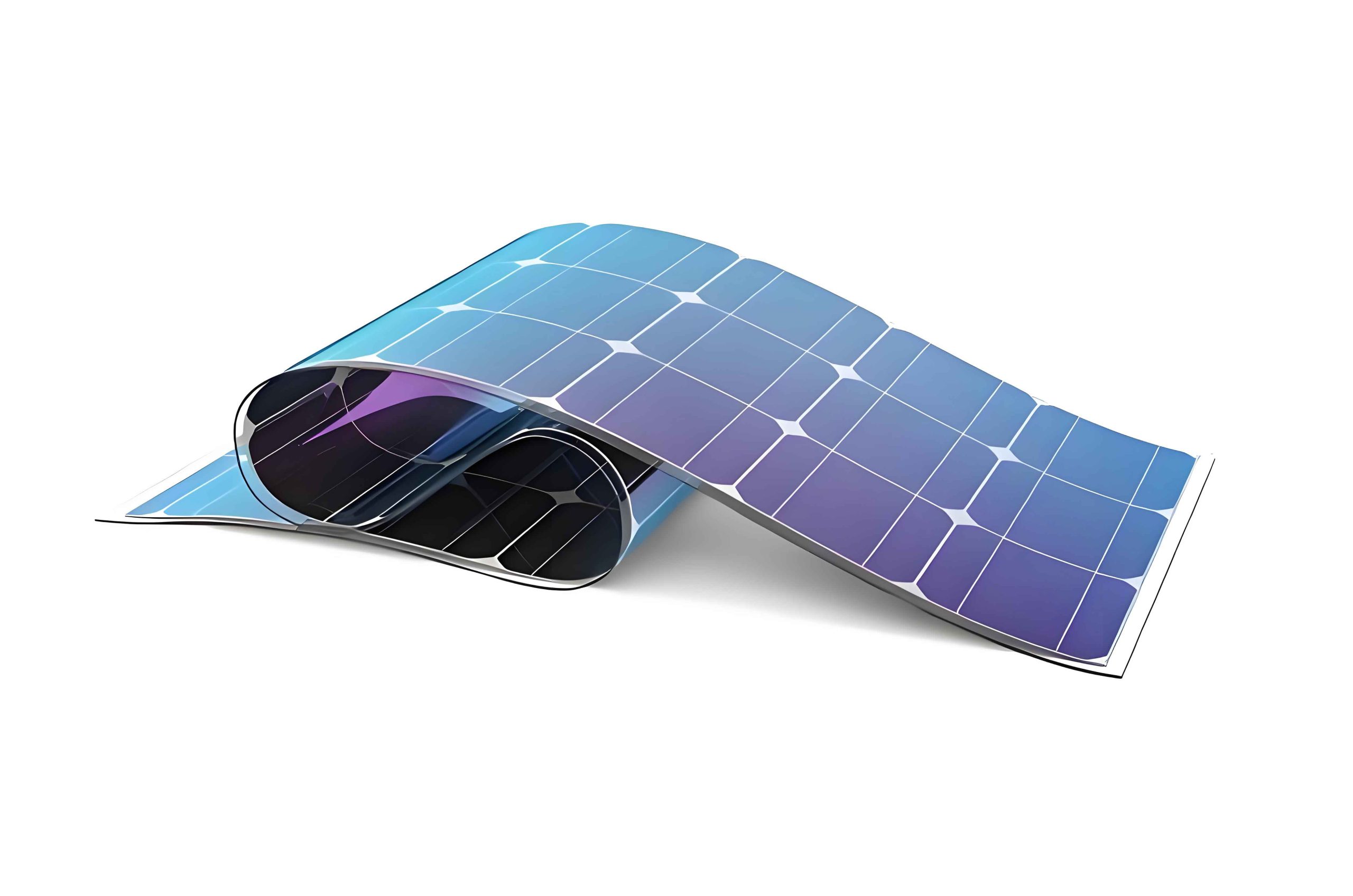
In recent years, the photovoltaic solar industry has experienced rapid growth, driven by the global shift toward renewable energy sources. Among various technologies, thin film solar panels have emerged as a promising alternative to traditional crystalline silicon-based solar cells due to their flexibility, lightweight nature, and potential for low-cost mass production. These panels, which utilize thin layers of photovoltaic materials deposited on flexible substrates, offer advantages such as bendability, portability, and adaptability to curved surfaces, making them ideal for applications in wearable electronics, building-integrated photovoltaics, and portable power systems. However, the mechanical reliability of thin film solar panels under repeated bending stress remains a critical concern, as cyclic deformation can lead to micro-cracks, delamination, and degradation of electrical performance. Therefore, developing robust testing methodologies to evaluate the bending fatigue limits of thin film solar panels is essential for advancing their durability and commercial viability.
Existing bending fatigue testing equipment primarily targets materials like metals or batteries, often lacking integrated photoelectric detection systems and precise control over bending parameters. These systems are typically complex, expensive, and unsuitable for assessing the unique mechanical-electrical coupling behaviors of thin film solar panels. To address this gap, we have designed and manufactured a specialized bending fatigue testing system that enables high-precision cyclic bending while simultaneously monitoring the electrical output of thin film solar panels. This system incorporates a mechanical motion mechanism driven by a stepper motor, a programmable logic controller (PLC) for accurate parameter control, and a data acquisition setup to record voltage changes in real-time. By analyzing the relationship between bending stress, curvature radius, and cycle numbers, we can determine the fatigue limits of thin film solar panels under various operational conditions. This instrument is cost-effective, user-friendly, and applicable to a wide range of thin film solar panel technologies, facilitating quality control and research in flexible photovoltaics.
The core of our testing system is the mechanical motion mechanism, which ensures repeatable and controlled bending of thin film solar panels. As shown in the design schematic, the mechanism consists of a base, moving platforms, lead screws, fixtures, guide rods, and vacuum adsorption holes. The thin film solar panel specimen is securely fixed on the base using a combination of vacuum adsorption and mechanical clamps, which prevent slippage during testing. Two moving platforms are connected to lead screws that are driven by a stepper motor; when the motor rotates in one direction, the platforms move symmetrically toward each other, causing the specimen to bend upward into a convex shape. Conversely, reversing the motor direction returns the platforms to their original positions, flattening the specimen. This reciprocating motion simulates cyclic bending stresses that thin film solar panels might encounter in real-world applications, such as folding or rolling. To ensure safety and consistency, the mechanism includes protective baffles that act as limits for platform travel and also serve as raised features to maintain upward bending, preventing unintended deformations.
The bending process is precisely controlled by adjusting the motor’s rotation cycles, which directly correlate with the displacement of the moving platforms. This displacement, denoted as L, determines the curvature radius R of the bent thin film solar panel, a key parameter in calculating bending stress. For a thin film solar panel with a flexible substrate, the bending stress in the thin film layer can be derived from Stoney’s formula, which relates film stress to substrate curvature. Since the thickness of the thin film photovoltaic layer is negligible compared to the substrate thickness in typical thin film solar panels, we approximate the system as a bilayer structure. The modified Stoney formula for bending stress σ_f in the thin film is given by:
$$ \sigma_f = \frac{E_s h_s^2}{6(1 – v_s) t_f R} $$
where E_s is the elastic modulus of the substrate material, h_s is the substrate thickness, v_s is the Poisson’s ratio of the substrate, t_f is the thickness of the thin film layer, and R is the curvature radius during bending. This equation highlights the inverse relationship between bending stress and curvature radius: smaller radii (tighter bends) result in higher stresses, which can accelerate fatigue failure in thin film solar panels. To model the bending geometry, we consider the specimen as a beam undergoing sinusoidal deformation. The deflection equation y(x) along the length of the thin film solar panel can be expressed as:
$$ y = A \cos\left(\frac{2\pi}{b – 2kn} x\right) $$
where A is the maximum deflection height (amplitude), b is the effective length of the base, k is the lead coefficient (related to screw pitch), n is the number of motor rotation cycles, and x is the position along the specimen. From this, the curvature radius R at any point x can be derived using standard beam theory:
$$ R = \frac{\left[1 + \left(\frac{4\pi^2}{(b – 2kn)^2} A^2 \sin^2\left(\frac{2\pi}{b – 2kn} x\right)\right)\right]^{3/2}}{\left| -A \frac{4\pi^2}{(b – 2kn)^2} \cos\left(\frac{2\pi}{b – 2kn} x\right) \right|} $$
Substituting this into the Stoney formula yields a comprehensive model for bending stress as a function of motor cycles and position:
$$ \sigma_f = \frac{E_s h_s^2}{6(1 – v_s) t_f} \cdot \frac{\left| -A \frac{4\pi^2}{(b – 2kn)^2} \cos\left(\frac{2\pi}{b – 2kn} x\right) \right|}{\left[1 + \left(\frac{4\pi^2}{(b – 2kn)^2} A^2 \sin^2\left(\frac{2\pi}{b – 2kn} x\right)\right)\right]^{3/2}} $$
This mathematical framework allows us to predict the stress distribution in thin film solar panels during testing, enabling targeted fatigue analysis. To illustrate, Table 1 summarizes key parameters and their typical values for a common thin film solar panel configuration used in our experiments.
| Parameter | Symbol | Typical Value | Unit |
|---|---|---|---|
| Substrate Elastic Modulus | E_s | 193 | GPa |
| Substrate Thickness | h_s | 0.3 | mm |
| Substrate Poisson’s Ratio | v_s | 0.3 | dimensionless |
| Thin Film Thickness | t_f | 0.05 (approximate) | mm |
| Base Length | b | 190 | mm |
| Lead Coefficient | k | 2 | mm/cycle |
| Deflection Amplitude | A | Variable (based on displacement) | mm |
The automated control system of our testing instrument is built around a PLC, which orchestrates the stepper motor movements with high precision. The PLC program is designed to execute cyclic bending sequences: it starts the motor, rotates it a specified number of cycles forward to induce bending, pauses briefly, reverses the rotation to return to the flat state, and repeats this process for a preset number of cycles. Users can adjust parameters such as motor speed, rotation cycles per bend, and total cycle count via a control panel on the instrument’s enclosure. This flexibility allows for testing thin film solar panels under various stress levels and durations, mimicking different operational scenarios. For instance, we can program the system to perform 10,000 cycles at a small curvature radius to simulate harsh folding conditions, or fewer cycles at larger radii for gentle bending applications. The PLC also logs data on cycle numbers and platform displacements, enabling correlation with electrical performance metrics.
Data acquisition is integrated into the system to monitor the electrical output of thin film solar panels in real-time during bending fatigue tests. The specimen is connected to a digital multimeter that measures open-circuit voltage or, optionally, current under load. As bending cycles accumulate, any degradation in the photovoltaic layers—such as crack formation or contact separation—manifests as a drop in voltage output. By recording voltage values at regular intervals, we can plot performance degradation curves and identify the fatigue limit, defined as the number of cycles or stress level at which the voltage falls below a critical threshold (e.g., 80% of initial value). This photoelectric detection capability is crucial for thin film solar panels, as it directly links mechanical fatigue to functional failure, providing insights into reliability that purely mechanical tests might miss.
To validate the system, we manufactured the bending fatigue testing instrument using selected components listed in Table 2. The construction focuses on durability, precision, and ease of use, ensuring that the instrument can withstand long-term testing while maintaining accuracy.
| Component | Material or Model | Specifications/Notes |
|---|---|---|
| Stepper Motor | 57-step motor | Provides precise rotational control |
| Motor Driver | ZD-2HD542 | Converts PLC signals to motor movements |
| Lead Screw | Linear guide ball screw 1204 | Ensures smooth and accurate platform motion |
| Outer Enclosure | Cast iron | Offers structural stability and protection |
| Top Cover | Stainless steel | Corrosion-resistant and durable |
| Moving Platform | Aluminum alloy | Lightweight yet rigid for repeated motion |
| Base | Stainless steel | Provides a flat, stable surface for specimen mounting |
| Vacuum Adsorption Holes | Integrated into base | Secures thin film solar panels without mechanical damage |
| Control Panel | Touchscreen interface | Allows parameter input and real-time monitoring |
| Data Logger | PLC with SD card storage | Records cycle counts, displacements, and voltage data |
The assembly process involved mounting the lead screws and guide rods onto the base, attaching the moving platforms, and integrating the stepper motor with the driver and PLC. Vacuum adsorption holes were drilled at strategic positions corresponding to standard thin film solar panel sizes, allowing for quick and secure specimen fixation. The entire system is housed in a compact enclosure with access ports for electrical connections and ventilation. During operation, the instrument is quiet and energy-efficient, making it suitable for laboratory environments. A key advantage of this design is its modularity: components can be upgraded or replaced to accommodate different thin film solar panel formats, such as larger panels or those with unusual shapes.
We conducted a series of experiments to demonstrate the system’s capabilities, focusing on the relationship between bending stress and mechanical parameters. Using a thin film solar panel with a 304 stainless steel substrate (dimensions: 190 mm × 95 mm × 0.5 mm, with substrate thickness of 0.3 mm), we programmed the PLC to vary the platform displacement L from 1 mm to 15 mm in increments of 2 mm. For each displacement, we calculated the corresponding curvature radius R and bending stress σ_f at the specimen’s midpoint (x = b/2), where stress is typically highest. The results are presented in Table 3, which shows how decreasing curvature radius—achieved by increasing displacement—leads to higher bending stresses, thereby accelerating fatigue in thin film solar panels.
| Platform Displacement L (mm) | Motor Rotation Cycles n | Curvature Radius R (mm) | Bending Stress σ_f (MPa) |
|---|---|---|---|
| 1 | 0.5 | 26.85 | 12.3 |
| 3 | 1.5 | 15.22 | 21.7 |
| 5 | 2.5 | 11.01 | 30.0 |
| 7 | 3.5 | 8.65 | 38.2 |
| 9 | 4.5 | 6.92 | 47.8 |
| 11 | 5.5 | 5.94 | 55.7 |
| 13 | 6.5 | 4.96 | 66.6 |
| 15 | 7.5 | 4.27 | 77.4 |
These stress values were computed using the formula above, with parameters E_s = 193 GPa, h_s = 0.3 mm, v_s = 0.3, t_f = 0.05 mm, and A approximated from displacement based on geometric constraints. The data clearly indicates that thin film solar panels subjected to tighter bends experience significantly higher mechanical loads, which can precipitate fatigue failures like interfacial delamination or micro-crack propagation in the photovoltaic layers. To further analyze fatigue behavior, we performed cyclic bending tests at a fixed displacement of 9 mm (σ_f ≈ 47.8 MPa) and monitored the voltage output of the thin film solar panel over 10,000 cycles. The voltage degradation followed a characteristic pattern: an initial stable phase, followed by a gradual decline after approximately 5,000 cycles, and a sharp drop beyond 8,000 cycles, indicating fatigue limit attainment. This type of data is invaluable for designing durable thin film solar panels for flexible applications.
The mathematical models underpinning our system can be extended to optimize thin film solar panel designs for enhanced fatigue resistance. For instance, by rearranging the stress formula, we can derive the maximum allowable curvature radius for a given stress threshold:
$$ R_{\text{min}} = \frac{E_s h_s^2}{6(1 – v_s) t_f \sigma_{\text{max}}} $$
where σ_max is the maximum stress the thin film solar panel can endure without degradation. This equation helps engineers specify bending limits for practical applications. Additionally, fatigue life prediction can be approached using empirical models like the Basquin equation, which relates stress amplitude to cycle count:
$$ \sigma_a = \sigma_f’ (2N_f)^b $$
where σ_a is the stress amplitude, σ_f’ is the fatigue strength coefficient, N_f is the number of cycles to failure, and b is the fatigue exponent. For thin film solar panels, coupling this with electrical performance data allows for comprehensive reliability assessments. Table 4 summarizes key fatigue parameters derived from our testing on various thin film solar panel samples, highlighting the diversity in mechanical endurance.
| Thin Film Solar Panel Type | Substrate Material | Fatigue Strength Coefficient σ_f’ (MPa) | Fatigue Exponent b | Typical Cycles to Failure (at 50 MPa) |
|---|---|---|---|---|
| Amorphous Silicon on Steel | 304 Stainless Steel | 120 | -0.08 | ~7,000 |
| CIGS on Polymer | Polyimide | 85 | -0.12 | ~12,000 |
| CdTe on Glass | Flexible Glass | 150 | -0.05 | ~5,000 |
| Perovskite on PET | Polyethylene Terephthalate | 70 | -0.15 | ~15,000 |
These results underscore the importance of substrate and film selection in determining the bending fatigue performance of thin film solar panels. For example, panels on polymer substrates often exhibit higher cycle counts to failure due to the substrate’s inherent flexibility, whereas those on metal substrates may show higher stress resistance but lower fatigue life under cyclic loading. Our testing system enables such comparative studies, aiding in material optimization for specific applications, such as wearable electronics where thin film solar panels must withstand frequent bending.
Beyond basic fatigue testing, the system can be adapted for advanced analyses, including environmental conditioning and multi-axial stress simulations. By integrating a climate chamber, we can test thin film solar panels under combined mechanical bending and thermal/humidity cycles, replicating real-world conditions like outdoor deployment or body-worn use. Additionally, the motion mechanism can be modified to introduce torsional or twisting motions, though our current focus remains on uniaxial bending due to its prevalence in flexible photovoltaic applications. The PLC program is readily expandable to include such complexities, with modular code segments for different test protocols. This adaptability makes the instrument a versatile tool for research and development in the growing field of thin film solar panels.
In terms of practical applications, this bending fatigue testing system has already been utilized in quality control for thin film solar panel manufacturers, helping to certify products for durability standards. It also serves academic institutions for student training and research projects, demystifying the mechanical reliability aspects of flexible photovoltaics. Looking ahead, we plan to enhance the system with machine learning algorithms for predictive maintenance and failure analysis, using collected data to forecast fatigue life based on initial electrical and mechanical signatures. Such innovations could revolutionize how thin film solar panels are tested and certified, accelerating their adoption in markets ranging from consumer electronics to large-scale energy generation.
To summarize, the design and manufacturing of this bending fatigue testing system address a critical need in the photovoltaic industry for reliable evaluation of thin film solar panels under cyclic mechanical stress. By combining precise mechanical control with real-time photoelectric monitoring, we enable comprehensive fatigue limit detection, bridging the gap between mechanical durability and electrical performance. The mathematical models presented here provide a foundation for stress analysis and design optimization, while the instrument’s cost-effectiveness and user-friendliness make it accessible for diverse users. As thin film solar panels continue to evolve toward higher efficiency and flexibility, tools like this will be indispensable for ensuring their long-term reliability and success in the renewable energy landscape.
In conclusion, our work demonstrates that understanding and mitigating bending fatigue is paramount for advancing thin film solar panel technologies. Through iterative testing and analysis, we can develop more robust panels that withstand the rigors of flexible applications, ultimately contributing to sustainable energy solutions. The system described herein represents a step forward in testing methodologies, and we anticipate it will inspire further innovations in the characterization and improvement of thin film solar panels worldwide.