
In the pursuit of renewable energy solutions, thin film solar panels have emerged as a promising technology due to their low cost, flexibility, and potential for large-scale deployment. Among various materials, amorphous silicon (a-Si:H) based thin film solar panels are particularly attractive because of their relatively simple fabrication process and decent optoelectronic properties. However, a-Si:H suffers from structural disorder, leading to defects that hinder carrier transport and increase recombination losses, especially at interfaces within the device structure. In this study, I explore the impact of inserting buffer layers at the p/i and i/n interfaces of a pin-type amorphous silicon thin film solar panel on its performance through numerical simulation. The goal is to enhance the conversion efficiency by mitigating interface defects and band discontinuities, which are critical challenges in optimizing thin film solar panels.
The inherent atomic structure of amorphous silicon is characterized by a covalent random network, exhibiting short-range order but long-range disorder. This disordered nature results in numerous structural defects and microvoids, creating localized defect states deep within the energy gap. These states act as recombination centers, reducing the carrier lifetime and overall device efficiency. In heterojunction solar cells, such as those in thin film solar panels, interface defects are unavoidable due to lattice mismatch between different layers. For instance, in a standard pin structure with p-type amorphous silicon carbide (p-a-SiC:H), intrinsic amorphous silicon (i-a-Si:H), and n-type amorphous silicon (n-a-Si:H), the transitions at the p/i and i/n interfaces can lead to band spikes or notches that impede carrier collection. To address this, I propose the use of buffer layers—thin, graded material regions—to smoothen the band alignment and reduce recombination at these interfaces. This approach is crucial for advancing the performance of thin film solar panels, making them more competitive in the photovoltaic market.
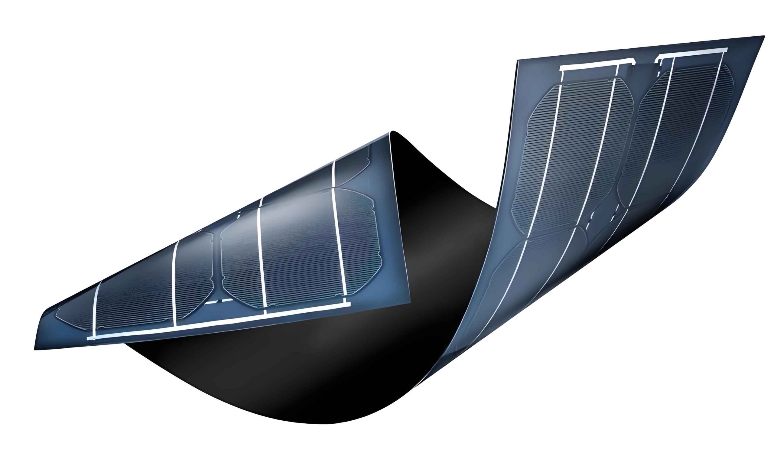
To systematically investigate this, I developed a numerical model based on a single-junction pin amorphous silicon thin film solar panel with the structure: TCO/p-a-SiC:H/i-a-Si:H/n-a-Si:H/back contact. The simulation incorporates buffer layers at both the p/i and i/n interfaces, each with a thickness of 4 nm, composed of nanocrystalline silicon (nc-Si:H) with tailored bandgaps to facilitate gradual transitions. The analysis focuses on how these buffer layers influence key performance parameters such as short-circuit current density ($J_{sc}$), open-circuit voltage ($V_{oc}$), fill factor (FF), and conversion efficiency ($\eta$). All simulations are conducted under standard AM1.5 solar spectrum illumination (100 mW/cm²), with ideal assumptions: zero reflection at the front transparent conductive oxide (TCO) electrode and perfect reflection at the back electrode. The carrier recombination mechanisms are modeled using the Shockley-Read-Hall (SRH) formalism, accounting for indirect recombination via defect states. The operating temperature is set to 300 K, and interface recombination velocities at both electrodes are assumed to be $1 \times 10^7$ cm/s, reflecting realistic boundary conditions for thin film solar panels.
The numerical simulations are performed using the AMPS-1D (Analysis of Microelectronic and Photonic Structures) software, which solves the coupled one-dimensional Poisson’s equation and electron/hole continuity equations through the Newton-Raphson method. This tool is widely employed for modeling carrier generation, recombination, and transport in photovoltaic devices, including thin film solar panels. The material properties of a-Si:H are described by the Mott-Davis model, which captures the density of states (DOS) in the bandgap due to disorder. The band tails, arising from dangling bonds and bond distortions, follow exponential distributions, while defect states in the mid-gap are attributed to structural imperfections. The DOS for conduction band tail ($g_c(E)$) and valence band tail ($g_v(E)$) are given by:
$$g_c(E) = g_{c0} \exp\left(-\frac{E_c – E}{E_A}\right)$$
$$g_v(E) = g_{v0} \exp\left(-\frac{E – E_v}{E_D}\right)$$
where $E_c$ and $E_v$ are the mobility edges of the conduction and valence bands, respectively; $E_A$ and $E_D$ are the characteristic energies for the band tails; and $g_{c0}$ and $g_{v0}$ are the prefactors. The mid-gap defect states are modeled as Gaussian distributions centered around specific energy levels, influencing recombination rates. These parameters are critical for accurately simulating the behavior of thin film solar panels, as they dictate carrier trapping and release processes.
For the simulation, I define the material parameters for each layer in the pin structure, as summarized in Table 1. The p-layer uses hydrogenated amorphous silicon carbide (a-SiC:H) with a wider bandgap to enhance light absorption in the blue region, while the i-layer is standard a-Si:H for efficient carrier generation. The n-layer is doped a-Si:H for electron collection. The buffer layers are introduced with intermediate bandgaps (1.72 eV at p/i and 1.68 eV at i/n) to reduce band offsets. Key parameters include thickness, bandgap, carrier mobilities, doping concentrations, and defect densities, all tailored based on experimental data for thin film solar panels.
| Parameter | P-layer (a-SiC:H) | I-layer (a-Si:H) | N-layer (a-Si:H) | Buffer Layers (nc-Si:H) |
|---|---|---|---|---|
| Thickness (nm) | 8 | 500 | 15 | 4 (each) |
| Mobility Bandgap ($E_\mu$, eV) | 1.96 | 1.80 | 1.80 | 1.72 (p/i), 1.68 (i/n) |
| Optical Bandgap ($E_g$, eV) | 1.90 | 1.72 | 1.72 | Same as $E_\mu$ |
| Relative Dielectric Constant ($\epsilon$) | 11.90 | 11.90 | 11.90 | 11.90 |
| Electron Mobility ($\mu_n$, cm²V⁻¹s⁻¹) | 5 | 20 | 10 | 15 |
| Hole Mobility ($\mu_p$, cm²V⁻¹s⁻¹) | 0.5 | 2 | 1 | 1.5 |
| Electron Affinity ($\chi$, eV) | 3.92 | 4.00 | 4.00 | 3.96 (p/i), 4.02 (i/n) |
| Doping Concentration ($N_A$ or $N_D$, cm⁻³) | $1 \times 10^{19}$ (p-type) | 0 | $3 \times 10^{19}$ (n-type) | 0 |
| Effective Density of States ($N_c$, $N_v$, cm⁻³) | $2.5 \times 10^{20}$ | $2.5 \times 10^{19}$ | $2.5 \times 10^{20}$ | $2.5 \times 10^{19}$ |
| Defect State Density ($N_{DG}$, $N_{AG}$, cm⁻³) | $5 \times 10^{17}$ | $5 \times 10^{17}$ | $5 \times 10^{17}$ | $1 \times 10^{17}$ |
| Band Tail Characteristic Energy ($E_A$, $E_D$, eV) | 0.03/0.05 | 0.03/0.05 | 0.03/0.05 | 0.02/0.04 |
| Mid-gap Defect Density ($N_t$, cm⁻³) | $3 \times 10^{18}$ | $5 \times 10^{16}$ | $9.5 \times 10^{18}$ | $1 \times 10^{16}$ |
With these parameters, I simulate the current density-voltage (J-V) characteristics of the thin film solar panel both with and without buffer layers. The results demonstrate a significant improvement in performance when buffer layers are incorporated. For the reference case without buffers, the conversion efficiency is 7.169%, with $J_{sc} = 14.749$ mA/cm², $V_{oc} = 0.880$ V, and FF = 0.552. In contrast, with optimized buffer layers, the efficiency increases to 7.474%, accompanied by $J_{sc} = 14.973$ mA/cm², $V_{oc} = 0.883$ V, and FF = 0.565. This represents an absolute efficiency gain of 0.305%, which is substantial for thin film solar panels where incremental improvements are highly valuable. The enhancement primarily stems from reduced interface recombination and better band alignment, as visualized in the band diagrams generated from the simulation.
The insertion of buffer layers at the p/i and i/n interfaces effectively lowers the potential barriers (band spikes) that typically form due to differences in electron affinity and bandgap between adjacent layers. In heterojunctions, these spikes act as traps for carriers, increasing the likelihood of recombination. By grading the bandgap through buffer layers, the transition becomes smoother, minimizing the spike height. This is quantified by the band offset reduction, which can be expressed as:
$$\Delta E_c = \chi_1 – \chi_2 – \Delta E_g$$
$$\Delta E_v = (E_{g1} – E_{g2}) – \Delta E_c$$
where $\Delta E_c$ and $\Delta E_v$ are the conduction and valence band offsets, $\chi$ is electron affinity, $E_g$ is bandgap, and subscripts denote different materials. For the p/i interface, the buffer layer with $E_g = 1.72$ eV reduces $\Delta E_c$ from approximately 0.08 eV to 0.02 eV, as calculated from the simulation data. Similarly, at the i/n interface, the buffer with $E_g = 1.68$ eV mitigates the offset. This reduction facilitates easier carrier transport across the interfaces, thereby boosting $J_{sc}$ and FF. Moreover, the buffer layers decrease the interface defect density by accommodating lattice mismatch, further suppressing recombination currents. The improvement in $V_{oc}$ is marginal but consistent with reduced recombination at interfaces, which lowers the saturation current density in the diode equation:
$$J = J_0 \left[\exp\left(\frac{qV}{nkT}\right) – 1\right] – J_{ph}$$
where $J_0$ is the reverse saturation current, $n$ is the ideality factor, $J_{ph}$ is the photocurrent, and other symbols have their usual meanings. A lower $J_0$ due to buffer layers contributes to a slightly higher $V_{oc}$, as observed. These mechanisms collectively enhance the performance of thin film solar panels, underscoring the importance of interface engineering.
To further analyze the impact, I examine the influence of buffer layer thickness on device performance. Varying the thickness from 1 nm to 7 nm while keeping other parameters constant reveals that the conversion efficiency peaks at around 4 nm and then gradually declines. As shown in the simulation results, $J_{sc}$ decreases monotonically with increasing thickness, while $V_{oc}$ and FF remain relatively unchanged. This behavior can be attributed to the trade-off between band-gap grading and parasitic absorption. Thinner buffer layers provide insufficient band smoothing, whereas thicker ones introduce additional absorption losses and series resistance, reducing the photocurrent. The efficiency ($\eta$) as a function of buffer layer thickness ($d$) can be approximated by:
$$\eta(d) = \eta_0 + \alpha d – \beta d^2$$
where $\eta_0$ is the efficiency without buffer, and $\alpha$ and $\beta$ are coefficients derived from fitting the simulation data. For the p/i buffer, $\alpha = 0.05$ %/nm and $\beta = 0.005$ %/nm², indicating an optimal thickness around 4-5 nm. This optimization is crucial for maximizing the benefits in thin film solar panels without introducing detrimental effects.
Additionally, I explore the role of buffer layer material properties, such as bandgap and defect density, on the overall device performance. By simulating variants with different bandgaps (ranging from 1.65 eV to 1.75 eV), I find that intermediate values close to 1.70 eV yield the best results, as they balance the band offsets at both interfaces. Lower defect densities in the buffer layers, as assumed in Table 1, further reduce recombination, highlighting the importance of high-quality material deposition in fabricating efficient thin film solar panels. The numerical model also allows me to calculate the internal electric field distribution, which is enhanced in the i-layer due to the buffer layers, promoting carrier drift and collection. The electric field ($E$) can be derived from Poisson’s equation:
$$\frac{dE}{dx} = \frac{q}{\epsilon} (p – n + N_D^+ – N_A^- + \rho_t)$$
where $q$ is the elementary charge, $\epsilon$ is permittivity, $p$ and $n$ are hole and electron densities, $N_D^+$ and $N_A^-$ are ionized dopants, and $\rho_t$ is the trap charge density. With buffer layers, the field in the intrinsic region becomes more uniform, reducing the regions of low field where recombination dominates. This is particularly beneficial for thin film solar panels with thick i-layers, where carrier collection is often limited by low fields.
In conclusion, this study demonstrates that inserting buffer layers at the p/i and i/n interfaces of amorphous silicon thin film solar panels can significantly improve conversion efficiency by reducing interface recombination and band discontinuities. Through numerical simulation using AMPS-1D, I achieve an efficiency of 7.474% with optimized buffer layers, compared to 7.169% without, representing a relative improvement of about 4.3%. The enhancement is attributed to increased $J_{sc}$ and FF, driven by smoother band alignment and lower potential barriers. The optimal buffer layer thickness is found to be around 4 nm, beyond which parasitic effects degrade performance. These insights underscore the critical role of interface engineering in advancing thin film solar panels, offering a pathway to higher efficiencies through simple structural modifications. Future work could involve experimental validation, extension to multi-junction designs, or exploration of other buffer materials like microcrystalline silicon, further pushing the boundaries of thin film solar panel technology. As the demand for cost-effective photovoltaics grows, such optimizations will be essential for making thin film solar panels a cornerstone of sustainable energy systems.
To generalize the findings, the principles discussed here apply not only to amorphous silicon but also to other thin film solar panel technologies, such as cadmium telluride (CdTe) or copper indium gallium selenide (CIGS), where interface management is equally important. By leveraging numerical simulations, researchers can rapidly prototype and optimize buffer layer designs without extensive experimental trials, accelerating the development of next-generation thin film solar panels. The integration of buffer layers represents a versatile strategy to enhance performance, stability, and scalability, ultimately contributing to the widespread adoption of thin film solar panels in diverse applications, from building-integrated photovoltaics to portable power sources.