
In the context of global environmental strategies and rapid technological advancement, the quest for sustainable and efficient power solutions for remote infrastructure has become paramount. As a professional engaged in maritime navigation systems, I have observed the persistent challenges in powering essential aids to navigation, such as beacons. This analysis explores the transition from conventional power methods to the innovative integration of thin film solar panels, offering a comprehensive technical and economic evaluation from a firsthand engineering perspective.
Beacons, critical for maritime safety, are often situated in isolated coastal areas, islets, or rocky outcrops. Their primary function requires reliable power for navigation lanterns, and increasingly, for ancillary systems like surveillance sensors or temporary maintenance lighting. The core challenge lies in delivering this power autonomously, reliably, and with minimal long-term maintenance and visual impact.
The total daily energy consumption (E_total) for a beacon is the sum of its subsystems. For a modern LED-based navigation lantern with a power draw P_nav (e.g., 7W) operating T_nav hours per day (typically 12-24h), and an auxiliary interior/security light with power P_aux (e.g., 15W) operating T_aux hours, the calculation is straightforward:
$$E_{total} (Wh/day) = (P_{nav} \times T_{nav}) + (P_{aux} \times T_{aux})$$
Considering system losses in the charge controller and battery (η_system ≈ 0.85), the required energy input from the photovoltaic source becomes:
$$E_{required} (Wh/day) = \frac{E_{total}}{\eta_{system}}$$
A comparative analysis of power requirements highlights the efficiency shift:
| Component | Old Technology (Incandescent) | Modern Technology (LED) | Power Saving |
|---|---|---|---|
| 4-NM Navigation Light | ~25 W | ~7 W | 72% |
| Internal Lighting (per 5m² area) | ~30 W (for 200 Lux) | ~15 W (for 100 Lux) | 50% |
Historically, two primary methods have been employed: grid connection and crystalline silicon (c-Si) photovoltaic systems. Grid connection, while reliable, is often economically and logistically prohibitive due to the high cost of trenching and installing protected cables over long distances to remote locations. The vulnerability of these lines to damage and theft also presents a significant security risk for unattended beacons.
The prevalent alternative has been crystalline silicon solar panels. The sizing methodology is standard. First, the Peak Sun Hours (PSH) for the location is determined. The required array power (P_array) is then calculated:
$$P_{array} (W_p) = \frac{E_{required}}{PSH \times \eta_{array}}$$
where η_array accounts for panel soiling, temperature losses, and mismatch. Traditionally, a rough empirical rule of thumb of 5Wp of solar panel per 1W of load has been used for reliable operation. Battery capacity (C_batt) is sized for autonomy (A_days, typically 5-7 days):
$$C_{batt} (Ah) = \frac{E_{total} \times A_{days}}{V_{system} \times DOD_{max}}$$
where V_system is the nominal voltage (e.g., 12V) and DOD_max is the maximum permissible Depth of Discharge (e.g., 0.5 for lead-acid).
While functional, c-Si systems present notable drawbacks for beacon integration. They require large, rigid, and heavy mounting structures on the beacon’s top platform, competing for space with the lantern itself and access hatches. This often leads to aesthetically unpleasing structures that detract from the minimalist design of modern beacons. Their performance plummets under diffuse or low-light conditions, necessitating significant oversizing to guarantee winter or rainy season operation. Furthermore, their glass-fronted construction is vulnerable to hail or vandalism, and the mounting structures require regular mechanical maintenance against corrosion.
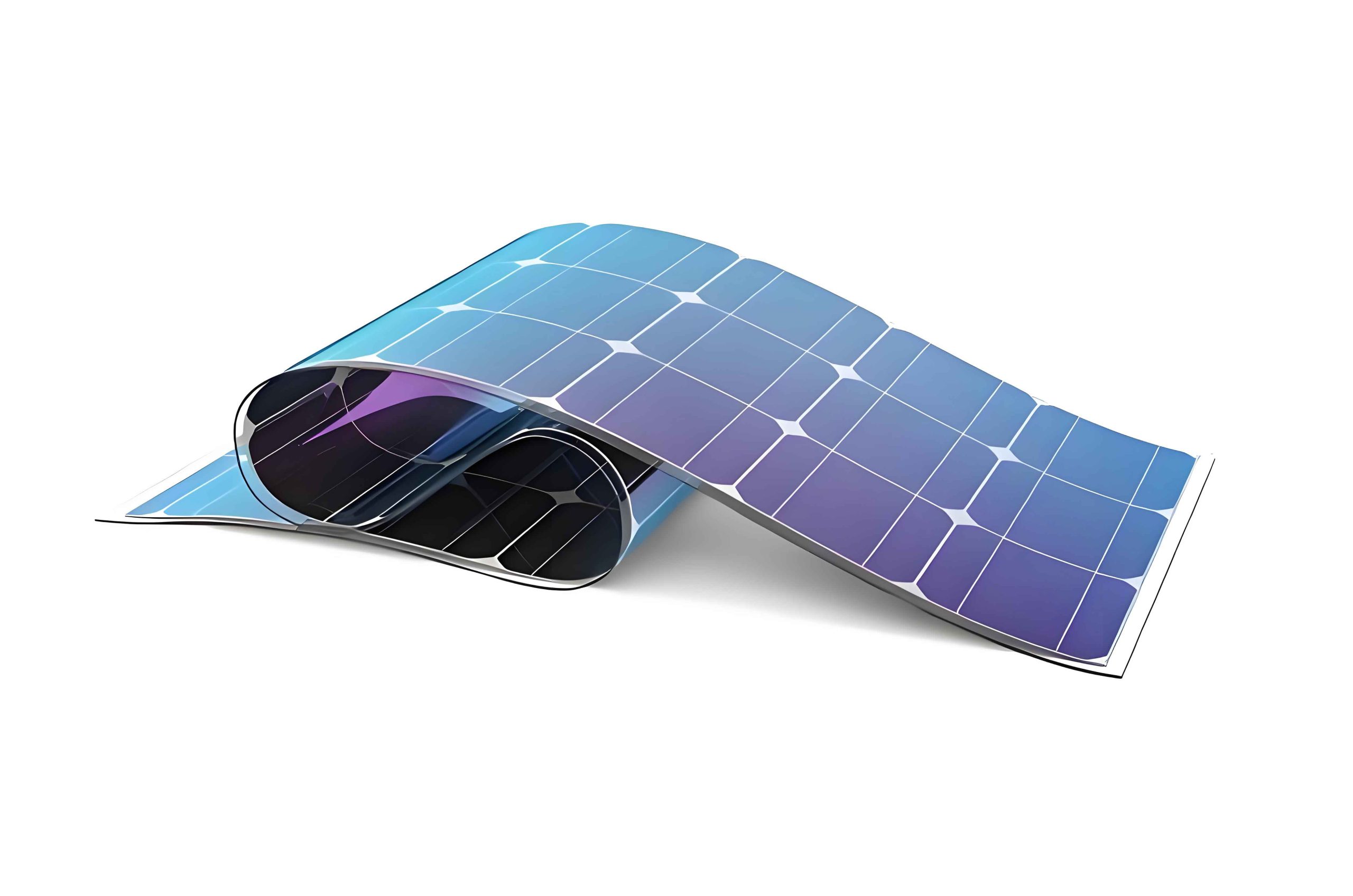
This is where the paradigm shift offered by thin film solar panels becomes compelling. Thin film photovoltaic technology, including amorphous silicon (a-Si), Cadmium Telluride (CdTe), and Copper Indium Gallium Selenide (CIGS), is fundamentally different from wafer-based c-Si. The active semiconductor material is deposited in layers micrometers thin onto a substrate.
The advantages of thin film solar panels for this application are multi-faceted:
1. Superior Low-Light and Diffuse Light Performance: The bandgap properties and inherent structure of thin film solar panels, particularly a-Si and CdTe, lead to a much better spectral response in cloudy, hazy, or dawn/dusk conditions. This can be modeled as a higher relative yield factor (f_lowlight > 1 compared to c-Si baseline) under low irradiance (G < 400 W/m²). The daily energy yield (E_yield) becomes more robust:
$$E_{yield} = \int_{day} P_{STC} \times \frac{G(t)}{G_{STC}} \times f_{lowlight}(G(t)) \times \eta_{temp}(T(t)) \, dt$$
where P_STC is panel power under standard test conditions, G_STC is 1000 W/m², and η_temp is a temperature-dependent efficiency factor.
2. Architectural and Structural Integration: This is the most transformative advantage. Thin film solar panels can be manufactured on flexible or rigid substrates like stainless steel, polymer, or glass. They can be directly integrated into the beacon’s cladding or superstructure. A curved beacon mast can be clad with flexible thin film solar panels, turning the entire visible surface into a power generator without protruding equipment. This BIPV (Building-Integrated Photovoltaics) approach eliminates separate mounting structures, reduces wind loading, and results in a sleek, uniform appearance. The mechanical durability of many thin film panels, especially those on metal substrates, is also superior against impact.
3. Economic and Manufacturing Advantages: The production of thin film solar panels involves significantly less high-purity semiconductor material due to their micron-scale absorption layers. They are manufactured via scalable, continuous deposition processes (like sputtering or vapor deposition) on large-area substrates, leading to lower embodied energy and cost per watt in high-volume production. While module efficiency in mass production for technologies like CdTe is around 18-19%, their superior real-world energy yield in non-ideal conditions and lower balance-of-system costs often result in a lower Levelized Cost of Energy (LCOE) for the installed system.
4. Temperature Coefficient: Thin film solar panels, particularly CdTe, typically have a significantly better (less negative) temperature coefficient than c-Si panels. This means their performance degrades less in hot climates, which is crucial for beacons exposed to full sun in coastal areas.
| Parameter | Crystalline Silicon (c-Si) | Thin Film Solar Panels (CdTe example) |
|---|---|---|
| Typical Module Efficiency | 19-22% | 17-19% |
| Low-Light Performance | Moderate | Excellent |
| Temperature Coefficient | -0.3 to -0.4 %/°C | -0.2 to -0.25 %/°C |
| Weight per kWp | High (~18-22 kg/kWp) | Low (~12-16 kg/kWp for glass-glass) |
| Integration Flexibility | Low (rigid, flat only) | High (flexible/curved options) |
| Annual Energy Yield (in temperate climate) | Baseline (1.0) | 1.05 – 1.10 x Baseline |
Implementing thin film solar panels on a beacon requires a revised design workflow. First is the selection of the thin film technology and substrate. For curved surfaces, flexible CIGS or a-Si on polymer/metal foil is ideal. For flat facade sections, rigid glass-based CdTe or a-Si panels offer high durability. Color is also a consideration; while dark blue/black is most efficient, some thin film solar panels can be made in dark bronze or grey for better architectural blending.
The key design step is re-calculating the required array size. Due to the superior low-light performance, the derating factor for “equivalent sun hours” can be adjusted. However, if panels are mounted vertically on the mast (common for aesthetic integration), their plane-of-array irradiance is reduced compared to a tilted top-mounted array. This must be modeled precisely using the solar azimuth and elevation angles for the site. The installed power (P_installed) needed on the vertical surface is:
$$P_{installed} = \frac{E_{required}}{PSH_{effective} \times \eta_{system}}$$
where PSH_effective is calculated from the transposition of horizontal irradiance to the vertical surface irradiance, factoring in the thin film solar panels’ enhanced diffuse light capture.
Electrical design involves running wiring from the integrated thin film solar panels through waterproof conduits embedded in the mast structure to a centralized electrical cabinet housing the charge controller, batteries, and load distribution. Modern Maximum Power Point Tracking (MPPT) charge controllers are essential to maximize harvest from the thin film solar panels, especially under varying light conditions. Lithium iron phosphate (LiFePO4) batteries are increasingly favored over lead-acid due to their longer lifespan, higher usable depth of discharge, and reduced maintenance, further optimizing the system.
A detailed cost-benefit analysis must consider the total lifecycle. While the initial cost per watt for the thin film solar panels themselves may be comparable, the significant savings come from the balance of system: elimination of heavy mounting structures, reduced installation labor, zero aesthetic penalty (potentially avoiding planning objections), and lower long-term maintenance. The enhanced reliability in poor weather may also allow for a modest reduction in battery autonomy requirements.
| Cost Component | Traditional c-Si Top-Mount System | Integrated Thin Film Solar Panel System |
|---|---|---|
| PV Modules | Cost per Wp * System Watts | Cost per Wp * System Watts |
| Mounting Structure & Hardware | High (custom steel platform, rails, clamps) | Very Low to Zero (integrated into cladding) |
| Installation Labor | High (crane/heavy lifting for top platform) | Lower (cladding installed during construction) |
| Aesthetic/Planning Risk | Potential cost for design mitigation | Negligible (inherently integrated design) |
| Lifetime Maintenance | Periodic cleaning, structural inspection | Minimal; cleaning as part of general structure washdown |
Looking forward, the evolution of thin film solar panels continues. Perovskite solar cells, which can be fabricated using thin-film techniques, promise even higher efficiencies and lower costs. Research into photovoltaic coatings or “solar paint” is ongoing. While not yet commercially durable for decades-long beacon service, it illustrates the ultimate goal: turning any exterior surface into a seamless, efficient power generator. For beacons, this could mean a future where the entire painted steel or concrete surface is the active power source, with wiring fully concealed within the wall.
In conclusion, the transition from bulky, add-on crystalline silicon systems to architecturally integrated thin film solar panels represents a significant technological leap for powering remote maritime beacons. The advantages are clear: superior energy harvest in real-world cloudy conditions, seamless and robust integration that enhances rather than detracts from the structure, and a compelling lifecycle cost proposition. As the technology for thin film solar panels matures and costs continue to decline, their adoption promises to set a new standard for reliable, maintenance-light, and visually sustainable power for critical coastal and maritime infrastructure. The future of beacon design is not about attaching power sources, but about constructing power-generating structures from the ground up, with thin film solar panels as an intrinsic component of the building envelope.