
In the pursuit of sustainable energy solutions, solar photovoltaic technology has emerged as a cornerstone. Among various solar cell types, thin film solar panels have garnered significant attention due to their potential for low-cost, high-efficiency, and flexible applications. As a researcher deeply immersed in this field, I find amorphous silicon (a-Si) based thin film solar panels particularly fascinating. Their unique properties and manufacturing processes offer a compelling alternative to traditional crystalline silicon solar cells. In this comprehensive analysis, I will delve into the fundamental characteristics, optical properties, material preparation methods, and component fabrication processes of amorphous silicon thin film solar panels. Throughout this discussion, I will emphasize the advantages and challenges associated with these thin film solar panels, aiming to provide a thorough understanding of their current state and future prospects.
The transition towards thin film solar panels is driven by the need to reduce material usage, lower energy consumption during production, and enable novel applications such as building-integrated photovoltaics (BIPV). Thin film solar panels, by their very nature, allow for shorter diffusion lengths for photogenerated carriers, which minimizes recombination losses and can lead to higher conversion efficiencies when light absorption is optimized. Amorphous silicon thin film solar panels represent a major category within this domain, alongside other thin film technologies like cadmium telluride (CdTe) and copper indium gallium selenide (CIGS). My focus here is on amorphous silicon, which has been extensively studied and deployed due to its relatively mature technology and adaptability.
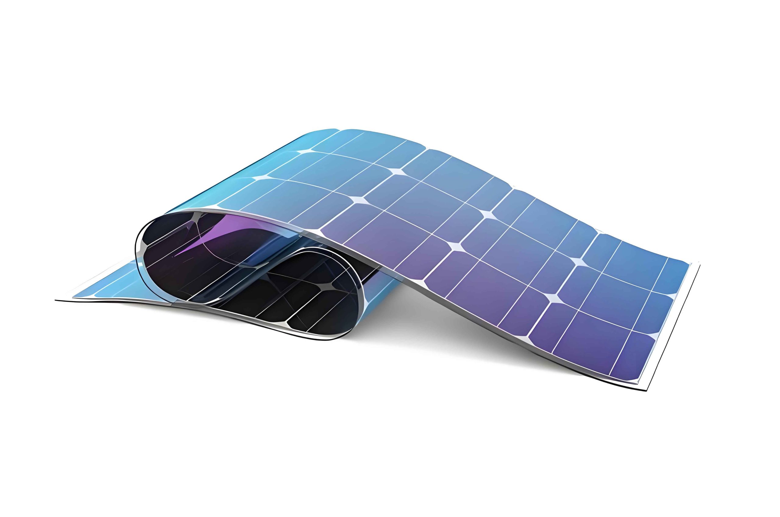
To begin, let’s explore the basic characteristics of amorphous silicon thin film solar panels. Compared to their crystalline silicon counterparts, these thin film solar panels exhibit several distinct advantages. First, the production energy requirement is significantly lower. Amorphous silicon films can be deposited at temperatures around 200°C, whereas crystalline silicon cells typically require processing above 1000°C. This reduction in thermal budget directly translates to lower manufacturing costs and a smaller carbon footprint. Second, amorphous silicon has a high optical absorption coefficient, especially in the visible light spectrum (0.3 to 0.75 μm), where it is about an order of magnitude higher than that of crystalline silicon. This means that thinner layers (typically 0.5 to 1 μm) can absorb a substantial portion of sunlight, reducing material consumption. Third, the flexibility in design is a key asset for thin film solar panels. Amorphous silicon cells can be fabricated in various configurations, including monolithic series-connected structures, which allow for higher output voltages and improved conversion efficiencies. Fourth, the manufacturing process is conducive to large-scale, continuous, and automated production, making it suitable for industrial rollout. Finally, the inherent flexibility of thin film technology enables seamless integration into building materials, facilitating the vision of BIPV where thin film solar panels become part of roofs, walls, and windows.
To quantify these advantages, consider the following table summarizing the key features of amorphous silicon thin film solar panels compared to traditional crystalline silicon panels:
| Characteristic | Amorphous Silicon Thin Film Solar Panels | Crystalline Silicon Solar Panels |
|---|---|---|
| Production Temperature | ~200°C | >1000°C |
| Absorption Coefficient (Visible Light) | 104 – 105 cm-1 | ~103 cm-1 |
| Typical Layer Thickness | 0.5 – 1 μm | 100 – 200 μm |
| Design Flexibility | High (flexible substrates, integrated structures) | Low (rigid wafers) |
| Manufacturing Scalability | Excellent (continuous roll-to-roll possible) | Good (batch processing) |
| BIPV Compatibility | Excellent | Moderate |
Moving on to the optical properties of amorphous silicon, it is essential to understand how light interacts with this material. The optical behavior of a semiconductor is fundamentally linked to electronic transitions between energy states. In crystalline semiconductors, these transitions obey momentum conservation rules, leading to distinct direct and indirect bandgap behaviors. However, in amorphous semiconductors like hydrogenated amorphous silicon (a-Si:H), the long-range disorder of the atomic network means that electronic states do not have well-defined wavevectors. Consequently, momentum conservation is relaxed, allowing for a broader range of optical transitions. This results in a unique absorption spectrum for a-Si:H, which can be divided into three regions: the fundamental absorption region, the band-tail absorption region, and the sub-bandgap absorption region. Analyzing these regions is crucial for optimizing the performance of thin film solar panels.
The absorption spectrum of a-Si:H is typically plotted as absorption coefficient (α) versus photon energy (hν). A schematic representation (though not referenced directly) shows that α varies over several orders of magnitude. In the fundamental absorption region (Region A), corresponding to photon energies above the optical bandgap, electrons are excited from the valence band to the conduction band. Here, α is relatively high, often exceeding 104 cm-1. This high absorption is precisely why amorphous silicon thin film solar panels can be so thin yet effective. The dependence of α on hν near the absorption edge follows the Tauc relation, which is expressed as:
$$(αhν)^{1/2} = B(E_g – hν)$$
where B is a constant related to the material’s properties (typically in the range of 105 to 106 cm-1eV-1), and E_g is the Tauc optical bandgap. The optical bandgap of a-Si:H typically ranges from 1.7 to 1.9 eV, depending on deposition conditions and hydrogen content. This bandgap can be tuned by alloying with elements like carbon or germanium, which is particularly useful for creating multi-junction thin film solar panels that capture a broader spectrum of sunlight.
In the band-tail absorption region (Region B), which corresponds to photon energies just below the optical bandgap, α drops to between 1 and 103 cm-1. This region arises from transitions involving band-tail states, which are localized states near the band edges due to disorder. The absorption here often exhibits an exponential dependence on hν, known as the Urbach tail, described by:
$$α(hν) = α_0 \exp\left(\frac{hν – E_0}{E_u}\right)$$
where α_0 is a constant, E_0 is a reference energy, and E_u is the Urbach energy, which characterizes the width of the band tails. A lower E_u indicates better material quality with fewer defects. For high-efficiency thin film solar panels, minimizing band-tail absorption is important to reduce parasitic losses.
The sub-bandgap absorption region (Region C) occurs at even lower photon energies (infrared range), where α is typically below 1 cm-1. This region is associated with transitions involving deep defect states within the bandgap, such as dangling bonds in a-Si:H. Absorption here is non-intrinsic and can be a measure of defect density. High-quality a-Si:H for thin film solar panels should exhibit very low sub-bandgap absorption to ensure good carrier collection and stability.
To encapsulate the optical characteristics, I present the following table detailing the three absorption regions:
| Absorption Region | Photon Energy Range | Absorption Coefficient (α) | Physical Origin | Impact on Thin Film Solar Panels |
|---|---|---|---|---|
| Fundamental (A) | hν > E_g | > 104 cm-1 | Band-to-band transitions | Primary light absorption for photocurrent |
| Band-tail (B) | Near E_g | 1 – 103 cm-1 | Transitions involving band-tail states | Can cause losses; minimized with good material quality |
| Sub-bandgap (C) | hν < E_g | < 1 cm-1 | Transitions via defect states | Indicates defect density; should be low for high performance |
The performance of amorphous silicon thin film solar panels is heavily influenced by the quality of the a-Si:H material, which in turn depends on the deposition technique. Over the years, numerous methods have been developed to prepare a-Si:H films, broadly categorized into chemical vapor deposition (CVD) and physical vapor deposition (PVD) techniques. For thin film solar panels, CVD methods are predominantly used due to their ability to produce high-quality films with controlled properties at relatively low temperatures. In my analysis, I will focus on three key CVD techniques: plasma-enhanced chemical vapor deposition (PECVD), hot-wire chemical vapor deposition (HWCVD), and photo-induced chemical vapor deposition (PICVD). Each method has its own principles, advantages, and drawbacks, which I will elaborate on in detail.
Plasma-enhanced chemical vapor deposition (PECVD) is the most widely used technique for fabricating amorphous silicon thin film solar panels, both in research and industry. In PECVD, a low-pressure plasma is generated using an external energy source, such as radio frequency (RF), very high frequency (VHF), or direct current (DC) power. This plasma dissociates precursor gases like silane (SiH4) diluted with hydrogen (H2), producing reactive species such as radicals, ions, and electrons. These species then adsorb onto a heated substrate (typically around 200°C) and form a solid a-Si:H film. The process involves several steps: primary reactions in the plasma, transport of species to the substrate, and surface reactions leading to film growth. The key parameters influencing film properties include plasma power, pressure, gas flow rates, substrate temperature, and excitation frequency.
PECVD offers excellent control over film composition and uniformity, making it ideal for depositing the multi-layer structures required for thin film solar panels (e.g., p-i-n junctions). For instance, by varying the gas mixture, one can deposit doped layers (p-type or n-type) using gases like diborane (B2H6) or phosphine (PH3). However, PECVD also has limitations. The plasma can cause ion bombardment, which may introduce defects or damage the film, especially at high powers. Additionally, the deposition rate is often limited to a few angstroms per second, which can be a bottleneck for mass production. To address this, very high frequency PECVD (VHF-PECVD) has been developed, which operates at frequencies between 30 and 300 MHz. VHF-PECVD can achieve higher deposition rates while maintaining good film quality, as it enhances plasma density without increasing ion energy excessively. This is particularly beneficial for scaling up thin film solar panels manufacturing.
Hot-wire chemical vapor deposition (HWCVD), also known as catalytic CVD, is another promising technique for depositing a-Si:H films for thin film solar panels. In HWCVD, a metal filament (usually tungsten or tantalum) is heated to high temperatures (1400°C to 1800°C) in a vacuum chamber. Precursor gases like SiH4 are introduced and decompose on the hot filament surface, generating atomic silicon and hydrogen. These atoms then diffuse to the substrate, where they recombine to form a film. The absence of plasma means there is no ion bombardment, potentially leading to films with lower defect densities. Moreover, HWCVD can achieve very high deposition rates (up to 10 nm/s or more), which is attractive for reducing production costs. The abundant atomic hydrogen produced during decomposition helps passivate dangling bonds, resulting in stable films with reduced light-induced degradation (Staebler-Wronski effect).
Despite its advantages, HWCVD faces challenges. The hot filaments can degrade over time, requiring replacement and increasing maintenance costs. There is also risk of filament material contaminating the film, though this can be mitigated by using refractory metals. Furthermore, achieving uniform deposition over large areas is difficult, as the filament temperature and gas flow dynamics must be carefully controlled. Ongoing research aims to optimize filament arrays and gas distribution systems to enable HWCVD for industrial-scale production of thin film solar panels.
Photo-induced chemical vapor deposition (PICVD) is a less common but interesting method that uses ultraviolet (UV) photons to dissociate precursor gases. In PICVD, a UV source (such as a mercury lamp or excimer laser) illuminates the gas mixture, creating reactive species without generating a plasma. This eliminates electric fields and ion bombardment, potentially yielding films with very low defect densities. However, PICVD suffers from slow deposition rates and issues with mercury contamination if mercury lamps are used. It is primarily used for specialized applications rather than mass production of thin film solar panels.
To compare these deposition techniques, I have compiled the following table:
| Deposition Method | Energy Source | Typical Deposition Rate | Advantages | Disadvantages | Suitability for Thin Film Solar Panels |
|---|---|---|---|---|---|
| PECVD (RF/VHF) | Plasma (RF/VHF power) | 1-5 Å/s | Excellent uniformity, good control, widely established | Ion bombardment damage, moderate rates | High (industry standard) |
| HWCVD | Hot filament | 1-10 nm/s | High rates, no ion damage, low H content | Filament degradation, contamination risk, uniformity challenges | Moderate (promising for R&D) |
| PICVD | UV photons | < 1 Å/s | No ion damage, low defect density | Very slow, potential mercury pollution | Low (specialized uses) |
Beyond material deposition, the fabrication of complete amorphous silicon thin film solar panels involves several intricate processes. These can be broadly divided into two categories based on the substrate: glass substrates and flexible substrates. Each approach has its own sequence of steps, which I will describe in detail.
For glass substrate thin film solar panels, the typical fabrication process starts with the preparation of transparent conductive oxide (TCO) glass. TCO layers, such as tin oxide (SnO2) or zinc oxide (ZnO), serve as the front contact, allowing light to enter while conducting electricity. The TCO must have high transparency (>80% in the visible range), low resistivity (< 10-3 Ω·cm), and a textured surface to enhance light trapping via scattering. This texture is crucial for thin film solar panels because it increases the effective path length of light within the absorber layer, boosting absorption. The TCO is usually deposited by spray pyrolysis or sputtering.
Next, the amorphous silicon layers are deposited using PECVD in a p-i-n configuration. For single-junction cells, this involves a thin p-type layer, a thick intrinsic (i) layer where most light absorption occurs, and a thin n-type layer. For multi-junction thin film solar panels (e.g., triple-junction a-Si/a-SiGe/a-SiGe), multiple p-i-n stacks are deposited sequentially, each designed to absorb different parts of the solar spectrum. After the silicon layers, a back reflector is deposited, typically consisting of a metal layer (like aluminum or silver) and a TCO layer (like ZnO) to reflect unabsorbed light back into the absorber. The cell is then patterned using laser scribing to create series-connected modules, which involves four laser cuts to isolate cells and interconnect them. Finally, the module undergoes testing, thermal aging to assess stability, and encapsulation to protect against environmental factors.
For flexible substrate thin film solar panels, the process often employs roll-to-roll (R2R) manufacturing, which enables continuous, high-throughput production. Flexible substrates can be stainless steel foil, polyimide, or polyethylene terephthalate (PET). The fabrication begins with cleaning the substrate via R2R washing. Then, a back reflector stack (metal/ZnO) is deposited by sputtering. The amorphous silicon p-i-n layers are deposited using PECVD in a multi-chamber system with isolation zones to prevent cross-contamination. After the silicon deposition, a front TCO (ITO) is sputtered. The continuous film is then laser-cut into individual cells, and a shunt-passivation step is performed to eliminate micro-shorts caused by particles. To collect current efficiently, a grid of busbars is printed on the front TCO, as the thin TCO alone has high sheet resistance. The edges are trimmed for insulation, and the cells are encapsulated between protective layers. The R2R approach is promising for low-cost, lightweight thin film solar panels, but challenges remain in achieving uniform deposition at high speeds and managing gas isolation between chambers.
To summarize the fabrication steps, here is a table comparing the two substrate approaches:
| Process Step | Glass Substrate Thin Film Solar Panels | Flexible Substrate Thin Film Solar Panels (R2R) |
|---|---|---|
| Substrate Preparation | Glass cleaning, TCO deposition (SnO2/ZnO) | R2R cleaning of metal/polymer foil |
| Back Contact/Reflector | Deposited after Si layers (Al/ZnO) | Deposited first (metal/ZnO by sputtering) |
| a-Si Deposition | PECVD p-i-n layers (single/multi-junction) | PECVD p-i-n layers in multi-chamber system |
| Front Contact | Integral with TCO glass | Sputtered ITO after Si deposition |
| Patterning | Four-step laser scribing for monolithic series connection | Laser cutting into cells, edge deletion |
| Additional Steps | Thermal aging, encapsulation | Shunt passivation, grid printing, encapsulation |
| Key Challenges | TCO quality, laser scribing accuracy | Uniformity at high speed, gas isolation, defect control |
In discussing the performance of amorphous silicon thin film solar panels, it is essential to consider efficiency metrics and stability issues. The initial efficiency of laboratory-scale single-junction a-Si cells has reached around 10-12%, while commercial modules typically achieve 6-8%. Multi-junction thin film solar panels (e.g., a-Si/μc-Si tandem) can attain stable efficiencies of 10-12% on modules. However, a-Si suffers from the Staebler-Wronski effect (SWE), where prolonged light exposure leads to a decrease in efficiency (up to 20-30% degradation) due to the creation of metastable defects. This has been a major hurdle for widespread adoption. Strategies to mitigate SWE include using thinner i-layers, incorporating hydrogen dilution during deposition to create more stable microcrystalline or nanocrystalline silicon, and developing multi-junction designs that reduce the thickness of each a-Si layer. Recent advances in light-induced defect annealing and improved passivation techniques are helping to enhance the stability of thin film solar panels.
From an economic perspective, the cost of amorphous silicon thin film solar panels has decreased significantly over the years, thanks to economies of scale and process improvements. The levelized cost of electricity (LCOE) for thin film solar panels is competitive in many regions, especially where space is not a constraint and low-light performance is valued. The flexibility and lightweight nature also reduce balance-of-system costs for certain installations. However, the rapid cost reduction of crystalline silicon panels has intensified competition. To remain viable, thin film solar panels must leverage their unique advantages, such as better temperature coefficients (lower efficiency loss at high temperatures), superior performance in diffuse light, and integration capabilities.
Looking ahead, the future of amorphous silicon thin film solar panels hinges on several research and development fronts. First, further improvements in deposition techniques are needed to increase rates, uniformity, and material quality. Hybrid approaches combining PECVD and HWCVD are being explored. Second, the development of novel tandem and multi-junction architectures using silicon-based alloys (e.g., a-SiGe, μc-Si) can push efficiencies beyond 15% stable. Third, advanced light management schemes, including photonic crystals and plasmonic structures, could enhance absorption without increasing thickness. Fourth, addressing the Staebler-Wronski effect through fundamental understanding of defect kinetics and passivation methods remains critical. Finally, scaling up flexible thin film solar panels production via R2R technology will open new markets in portable electronics, vehicles, and building-integrated systems.
In conclusion, amorphous silicon thin film solar panels represent a vital segment of the photovoltaic landscape. Their low-temperature processing, high absorption, design flexibility, and potential for low-cost mass production make them an attractive option for diverse applications. While challenges like light-induced degradation and competition from other technologies persist, ongoing research continues to advance the state of the art. As we strive for a sustainable energy future, thin film solar panels, including those based on amorphous silicon, will undoubtedly play a significant role. By optimizing materials, processes, and device architectures, we can unlock their full potential and contribute to the global transition to renewable energy.
Throughout this analysis, I have emphasized the multifaceted nature of amorphous silicon thin film solar panels, from fundamental optical properties to practical manufacturing. The integration of tables and formulas, such as the Tauc relation and Urbach tail expression, helps quantify key aspects. As a researcher, I believe that continued innovation in this field will yield more efficient, stable, and affordable thin film solar panels, paving the way for broader adoption. The journey of thin film solar panels is far from over, and I am excited to see how they evolve in the coming years.