
The rapid integration of renewable energy sources necessitates robust energy storage solutions, with lithium-ion battery technology, particularly the lifepo4 battery, playing a predominant role. However, the safety of these lifepo4 battery systems remains a critical challenge. Under thermal, electrical, or mechanical abuse, a lifepo4 battery can enter a self-accelerating exothermic chain reaction known as thermal runaway (TR). This process generates immense heat, flammable and explosive gases, and smoke, posing severe risks of fire and explosion within enclosed energy storage containers. Effective early detection is paramount to preventing catastrophic failure and cascading events in multi-cell lifepo4 battery packs. This article presents a comprehensive evaluation of sensor effectiveness and proposes a refined detection strategy based on experimental investigations conducted in a full-scale 40-foot energy storage container.
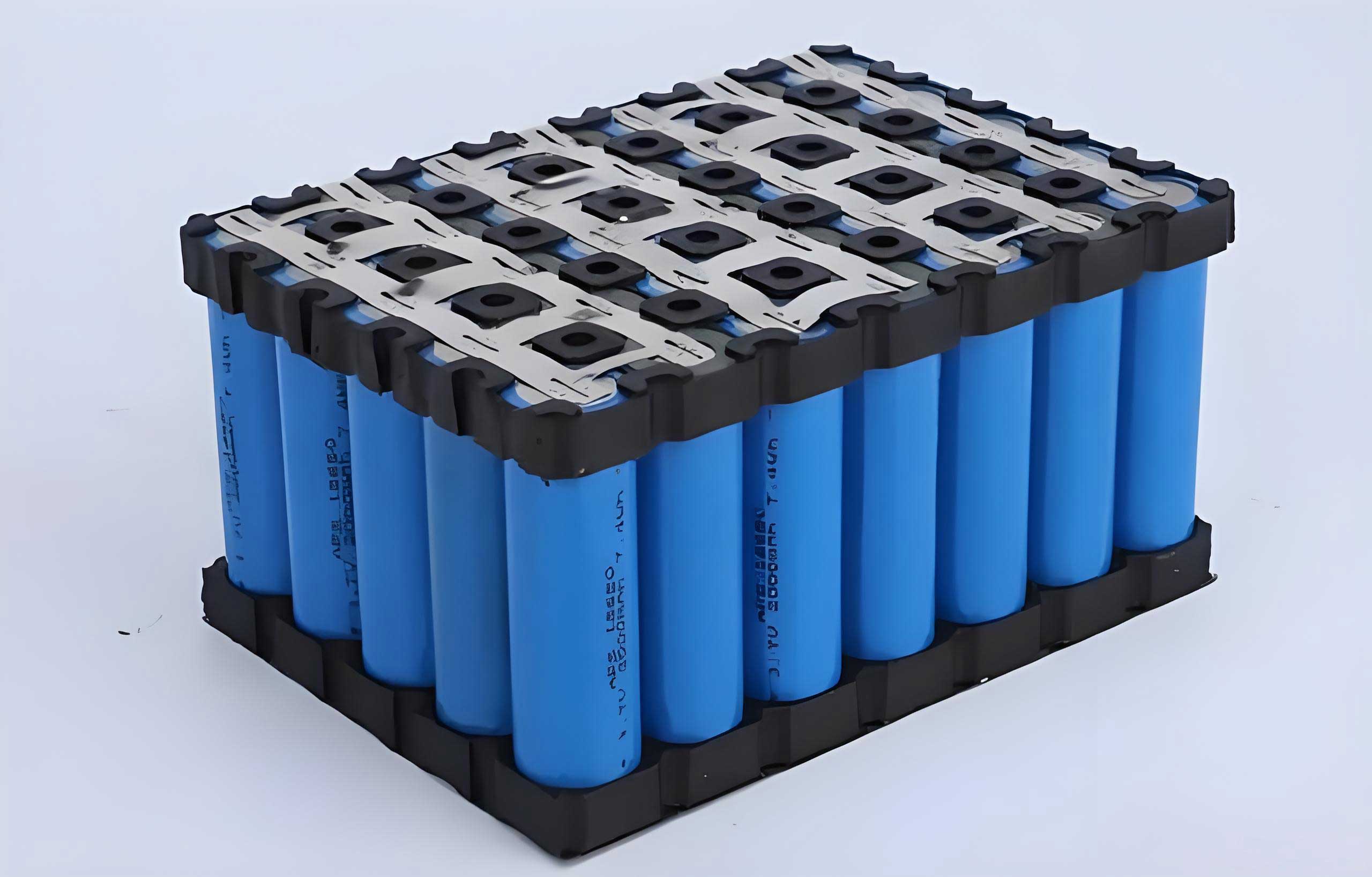
The core of an effective early warning system lies in the timely detection of TR characteristic parameters. During the failure of a lifepo4 battery, the cell undergoes complex internal reactions. The decomposition of the solid electrolyte interphase (SEI) layer is an early exothermic step, primarily releasing carbon dioxide (CO₂). Subsequent reactions between the lithiated anode and the electrolyte produce hydrogen (H₂), carbon monoxide (CO), and various volatile organic compounds (VOCs) from solvent decomposition. The heating of battery external components, such as the PET-based blue film, can also contribute to early VOC release. Simultaneously, the rapid temperature rise leads to separator melting, internal short circuits, and the violent venting of these accumulated gases and electrolyte vapors, culminating in smoke generation and potential ignition. Therefore, monitoring the volume fractions of H₂, CO, CO₂, VOCs, smoke density, temperature, and pressure provides a multi-faceted approach to identifying the onset and progression of a lifepo4 battery thermal runaway event.
Comparative Evaluation of Sensor Technologies for Lifepo4 Battery Monitoring
A critical step in designing a reliable detection system is selecting sensors with optimal response characteristics for a lifepo4 battery environment. Different sensing principles offer varying trade-offs in sensitivity, response time, selectivity, longevity, and cost. To evaluate this empirically, five distinct multi-parameter composite sensor packages (labeled A through E) were configured, each integrating a different combination of sensing principles for key gases, as summarized below.
| Sensor Package | H₂ Sensor Principle | VOC Sensor Principle | Other Key Parameters |
|---|---|---|---|
| A | Electrochemical | Solid Polymer Electrochemical | CO (Electrochemical), Smoke, Temperature |
| B | Semiconductor | Solid Polymer Electrochemical | CO, Smoke, Temperature |
| C | Electrochemical | Solid Polymer Electrochemical | CO, Smoke, Temperature, Pressure |
| D | Catalytic Combustion | Photoionization (PID) | CO (Electrochemical), CO₂, Smoke, Temperature |
| E | Semiconductor | Solid Polymer Electrochemical | CO, CO₂, Smoke, Temperature |
The experimental setup involved triggering thermal runaway in a commercial 280 Ah lifepo4 battery via a heating plate inside the full-scale container. Multiple sensor packages were distributed at different locations to study parameter propagation. The key findings from the sensor comparison are crucial for optimizing lifepo4 battery safety systems.
1. Hydrogen (H₂) Detection: The catalytic combustion-type H₂ sensor (in Package D) demonstrated a significantly faster response compared to both electrochemical and semiconductor types. It detected rising H₂ levels approximately 100 seconds earlier than the others. This faster response can be attributed to the direct catalytic oxidation mechanism, which is highly sensitive to the presence of combustible gases like H₂. For early warning in a lifepo4 battery pack, where every second counts to initiate countermeasures, the catalytic combustion principle offers a distinct advantage.
2. Volatile Organic Compounds (VOC) Detection: The photoionization detector (PID) for VOCs (in Package D) outperformed the solid polymer electrochemical sensor. The PID registered the first signs of VOC release nearly 600 seconds before the electrochemical sensor and well before other parameters like H₂ and CO saw a significant rise. This ultra-early detection is attributed to two factors: the early volatilization of electrolyte solvent upon initial heating and casing breach, and the thermal decomposition of the PET blue film wrapping the lifepo4 battery. The PID’s ability to detect a wide range of organic vapors with high sensitivity makes it an exceptional tool for the earliest possible indication of a compromised lifepo4 battery cell.
3. Other Parameters: Electrochemical CO sensors provided reliable detection concurrently with the main TR event. Infrared CO₂ sensors also effectively detected the gas but with a more delayed response, making them less ideal for early warning but potentially useful for confirmation and fire assessment. Semiconductor smoke detectors performed as expected during the venting and smoke generation phase. Temperature sensors at the container ceiling were ineffective for early TR detection without an open flame, but sensors placed near the module or measuring the gas temperature close to the cell could be valuable. Pressure sensors in the large container volume showed no measurable change from a single cell TR, indicating their limited utility for early detection at the container level, though they may be effective within a sealed battery module enclosure.
The superiority of catalytic combustion H₂ sensors and PID VOC sensors for early warning in a lifepo4 battery system is clearly established by this data. Their selection forms the cornerstone of a proactive detection strategy.
Sequence of Gas Generation and Propagation Dynamics
Understanding the temporal sequence of gas release during a lifepo4 battery thermal runaway event is key to designing a staged alarm strategy. The experimental data reveals a consistent pattern:
Stage 1: Early Warning (VOCs): The first detectable signature, often hundreds of seconds before violent venting, is a low-concentration rise in VOCs. This is primarily due to the heating and decomposition of external materials (blue film) and the initial leakage and volatilization of liquid electrolyte. The PID sensor is critical for capturing this stage. The concentration in this phase typically remains below $$10^{-4}$$ (100 ppm).
Stage 2: Venting and Gas Release (H₂, CO, Smoke): As internal pressure builds, the safety valve opens. This marks the transition to a more hazardous state. A rapid increase in H₂ concentration is detected first among the major flammable gases, followed closely by CO and visible smoke. The earlier detection of H₂ over CO aligns with the reaction pathways in a lifepo4 battery; H₂ generation from reactions with binders precedes the significant reduction of CO₂ to CO. The gas and smoke mixture forms a buoyant plume that rises to the container ceiling and then forms a ceiling jet, propagating horizontally.
Stage 3: Thermal Runaway and Combustion Products (CO₂): Following venting, intense internal heating leads to full thermal runaway. If ignition occurs, concentrations of CO, smoke, and CO₂ surge dramatically due to combustion, while H₂ and VOC concentrations decrease as they are consumed in the flame. CO₂ generation, both from internal reactions and combustion, shows a significant but later peak.
The propagation speed of these parameters across the container is vital for determining optimal sensor spacing. The speed depends on diffusion processes and the energy of the release. Under non-ignition conditions, the propagation is driven mainly by concentration diffusion and thermal buoyancy. The propagation velocity $$v$$ for a parameter between two sensors spaced 2400 mm apart can be calculated as:
$$v = \frac{2400}{t_{n+1} – t_n} \text{ mm/s}$$
where $$t_n$$ and $$t_{n+1}$$ are the detection times at the first and subsequent sensor, respectively. Experimental measurements yielded the following average propagation velocities for a cell failing in the middle of the container (non-ignition case):
| Parameter | Propagation Velocity (mm/s) | Notes |
|---|---|---|
| VOC | 15.41 | Slowest, early stage diffusion |
| Smoke | 21.75 | – |
| H₂ | 23.48 | – |
| CO | 27.21 | – |
| CO₂ | 35.71 | Fastest, released with higher energy |
When the failing lifepo4 battery is located near a wall, the propagation velocities increase because the wall confines and redirects the ceiling jet, effectively increasing its momentum. Furthermore, if the gases ignite, the resulting fire-driven thermal plume dramatically accelerates the spread of all parameters. For example, under ignition conditions, the propagation velocity for VOCs increased by a factor of 8.6, and for CO₂ by a factor of 5.45. This has direct implications for sensor placement and alarm timing requirements, which are often specified within a 30-60 second window after gas release.
Impact of Failure Location and Ignition on Detection
The location of the initiating lifepo4 battery cell and whether the vented gases ignite significantly influence the detection environment and parameter thresholds.
1. Cell Location (Edge vs. Center): A cell failing at the edge of the container exhibits faster parameter propagation along the ceiling compared to a centrally located cell, due to the wall confinement effect described earlier. This means edge-mounted detectors may see a slightly faster response. However, the characteristic gas generation sequence remains consistent. This factor must be accounted for when modeling detection coverage and verifying that all areas of the container are protected within the required time frame.
2. Ignition vs. Non-Ignition: The presence of an open flame drastically alters the gas composition and thermal environment, which affects sensor readings and alarm strategy. The comparative data is revealing:
| Parameter | Non-Ignition Peak | Ignition Peak | Effect of Ignition |
|---|---|---|---|
| H₂ Volume Fraction | > 2000 ppm | > 2000 ppm | Similar peak, but may be consumed by flame |
| CO Volume Fraction | ~684 ppm | > 1000 ppm | Significant Increase (Combustion intermediate) |
| VOC Volume Fraction | > 10,000 ppm | ~5778 ppm | Significant Decrease (Combustion consumption) |
| Smoke Density | ~4801 mg/m³ | > 10,000 mg/m³ | Major Increase (Soot from combustion) |
| CO₂ Volume Fraction | ~1296 ppm | > 5000 ppm | Major Increase (Complete combustion product) |
| Ceiling Temperature Rise Rate | ~0.10 °C/min | ~0.78 °C/min | 8-fold Increase |
This table highlights a critical point: relying on a single gas parameter, especially VOCs, for fire confirmation could be misleading, as its concentration may drop during a fire. Conversely, CO, CO₂, smoke, and temperature become dominant indicators of an active fire following a lifepo4 battery thermal runaway. Therefore, a robust detection logic must differentiate between the gas release phase (pre-fire) and the fire phase.
Proposed Integrated Detection Strategy and Sensor Placement for Lifepo4 Battery Compartments
Based on the experimental findings, a multi-level, parameter-fused detection strategy is recommended for enhancing the safety of lifepo4 battery energy storage systems. This strategy moves beyond single-threshold alarms to a state-aware system.
Level 1: Early Pre-Venting Warning (Pre-Alert).
- Primary Parameter: VOC concentration, measured by a PID sensor.
- Logic: A sustained rise in VOC concentration above a low background level (e.g., $$5 \times 10^{-5}$$ to $$1 \times 10^{-4}$$), especially with a positive rate-of-change, indicates cell heating, electrolyte leakage, or material decomposition. This alarm can trigger enhanced monitoring, cooling system activation, or an operator alert to investigate a specific module, potentially before any venting occurs.
Level 2: Thermal Runaway Gas Release Alarm (Main Alert).
- Primary Parameters: H₂ concentration (Catalytic Combustion sensor) and VOC concentration (PID).
- Supporting Parameters: CO concentration, smoke density.
- Logic: A rapid increase in H₂ concentration exceeding a threshold (e.g., $$5 \times 10^{-4}$$) is a definitive sign of venting flammable gas. This alarm should be confirmed by a concurrent high or rising VOC/CO/smoke signal. This level should trigger immediate and automated emergency procedures, such as initiating the fire suppression system for the affected cabinet and activating full ventilation.
Level 3: Fire Confirmation Alarm.
- Primary Parameters: Smoke density, CO concentration, temperature rise rate.
- Supporting Parameter: CO₂ concentration.
- Logic: Following a Level 2 alarm, a rapid and significant rise in smoke and CO, coupled with a sharp increase in local or ceiling temperature, confirms that an open fire has developed. This can be used to confirm the full deployment of suppression agents or trigger secondary safety protocols.
Sensor Selection and Placement Guidelines:
- Detector Type: Ceiling-mounted multi-criteria detectors are recommended. Each detector should ideally integrate a catalytic combustion H₂ sensor, a PID VOC sensor, an electrochemical CO sensor, and a photoelectric smoke sensor. An IR CO₂ sensor and a thermistor add valuable fire confirmation data.
- Spacing Calculation: Detector spacing should ensure that the propagating gas from a lifepo4 battery thermal runaway reaches a detector within the required response time (e.g., 60 seconds). Using the slowest relevant propagation velocity (VOC at ~15.41 mm/s under non-ignition, central fire) provides a conservative basis.
- Maximum travel distance in 60 s: $$d = v \times t = 15.41 \text{ mm/s} \times 60 \text{ s} \approx 925 \text{ mm}$$.
- Considering detection from both sides, the maximum recommended spacing between detectors in open areas is approximately $$2 \times 925 \text{ mm} = 1850 \text{ mm}$$ (1.85 m).
- For detectors near a wall, where propagation is faster (~21.3 mm/s for VOC), the spacing from the wall can be reduced: $$d_{wall} = 21.3 \text{ mm/s} \times 60 \text{ s} \approx 1278 \text{ mm}$$ (1.28 m).
Therefore, a practical layout would use a spacing of 1.5-1.8 m between detectors in the main area, with detectors placed within 0.6-1.3 m of any wall.
- Module-Level Monitoring: For the highest level of protection, especially in large lifepo4 battery racks, integrating point sensors for VOC or pressure within individual modules or clusters can provide the earliest possible localized warning, feeding into the overall container-level strategy.
In conclusion, safeguarding lifepo4 battery energy storage systems requires a sophisticated understanding of thermal runaway behavior and sensor performance. The integration of fast-responding catalytic combustion H₂ and PID VOC sensors forms the core of an effective early warning system. A detection strategy that logically combines these parameters in a staged sequence—from early VOC pre-alert to gas release alarm and finally fire confirmation—provides a robust framework for timely intervention. Adhering to calculated sensor spacing guidelines ensures comprehensive coverage, allowing for the rapid detection of a failing lifepo4 battery anywhere within the container, thereby significantly mitigating the risk of large-scale fire and explosion.