
Operating a grid-tied inverter, a critical interface for renewable energy systems, under unbalanced grid voltage conditions presents a significant challenge to power quality and system reliability. Conventional control strategies, designed assuming perfectly symmetrical three-phase grid voltages, often degrade severely when faced with voltage imbalances caused by faults or unequal loads. The primary manifestations include the generation of a second-order harmonic ripple in the DC-link voltage and distorted grid currents. The DC voltage ripple can stress capacitors, induce torque pulsations in generator systems, and ultimately, the distorted current pollutes the grid. This necessitates the development of specialized control algorithms that enable the grid-tied inverter to maintain high-performance operation even during unbalanced grid conditions, ensuring stable power delivery and longevity of system components.
Traditional approaches to this problem often involve complex sequence decomposition and multiple proportional-integral (PI) regulators in dual synchronous reference frames, or the use of proportional-resonant (PR) controllers. These methods, while effective, can impose substantial computational burdens and complexity in tuning. This article presents a novel, simplified control strategy based on a spatial phase analysis of the grid voltage vector. The core innovation lies in directly deriving the current reference commands for the grid-tied inverter from the instantaneous phase relationship between the positive and negative sequence voltage components, eliminating the need for explicit extraction of positive and negative sequence current components. Furthermore, a specially designed proportional discrete integrator replaces the standard PI controller to achieve zero steady-state error for the double-grid-frequency oscillating current components, fundamentally suppressing the DC-link voltage ripple and current distortion.
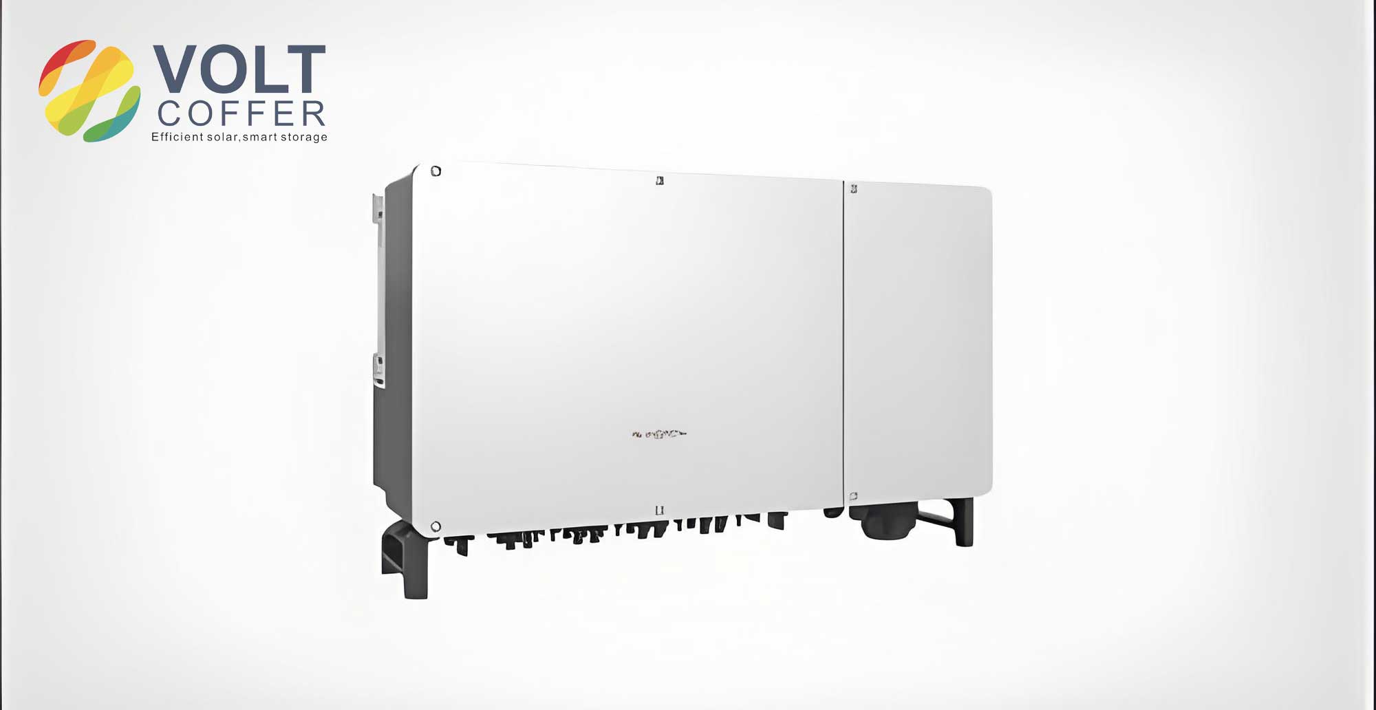
Mathematical Modeling and Spatial Phase Analysis
Under unbalanced conditions, the three-phase grid voltages can be decomposed into positive and negative sequence components using the theory of symmetrical components. The spatial voltage vector E in the stationary αβ-frame can be expressed as:
$$
\mathbf{E} = E_{+} e^{j(\omega_0 t + \phi_{+})} + E_{-} e^{j(-\omega_0 t + \phi_{-})}
$$
where $E_{+}$ and $E_{-}$ are the magnitudes, $\omega_0$ is the fundamental grid angular frequency, and $\phi_{+}$ and $\phi_{-}$ are the initial phase angles of the positive and negative sequence components, respectively. Similarly, the current vector I injected by the grid-tied inverter is:
$$
\mathbf{I} = I_{+} e^{j(\omega_0 t + \theta_{+})} + I_{-} e^{j(-\omega_0 t + \theta_{-})}
$$
where $I_{+}$, $I_{-}$, $\theta_{+}$, and $\theta_{-}$ are the corresponding magnitudes and phase angles for the current.
The primary control objective for the grid-tied inverter under voltage imbalance is often to maintain a constant instantaneous active power output. This condition is crucial for eliminating the second-order harmonic pulsation in the DC-link voltage. It can be shown that for constant instantaneous active power, the positive and negative sequence voltage and current components must satisfy the following phase relationship:
$$
\angle I_{+} – \angle E_{+} + \angle I_{-} – \angle E_{-} = \pm 180^\circ
$$
To exploit this relationship, we analyze the spatial movement of the voltage vector. Let $t_0$ be the instant when the positive and negative sequence voltage vectors are aligned (i.e., at their “coincidence angle” $\phi_0$). At this moment, the composite voltage vector is $\mathbf{E_0} = (E_{+} + E_{-})e^{j\phi_0}$. From $t_0$ to any time $t$, the positive sequence vector rotates by an angle $\psi = \omega_0 (t – t_0)$, and the negative sequence vector rotates by $-\psi$. The spatial phase relationship is illustrated in the figure below, which is key for the controller of the grid-tied inverter.
From the geometry, the phase angles of the positive and negative sequence voltages at time $t$ relative to $\phi_0$ are $\phi_{+}(t) = \phi_0 + \psi$ and $\phi_{-}(t) = \phi_0 – \psi$. The angles $\delta_1$ and $\delta_2$ relate the current vector phases to the voltage vector phases. The critical task for the grid-tied inverter controller is to determine the correct current vector magnitude and phase $\angle I(t)$ that satisfies the constant power condition. Through geometric and trigonometric analysis of the vector diagram, the phase angle $\theta_1 = \angle I_{+} – \angle E_{+}$ can be determined from the average active power $P$ and reactive power $Q$ commands:
$$
\theta_1 = \arctan\left(\frac{Q}{P}\right)
$$
Subsequently, the required phase lead $\Delta(t)$ of the total current vector $\mathbf{I}(t)$ ahead of the total voltage vector $\mathbf{E}(t)$ can be derived as a function of $\theta_1$, $\psi$, and the voltage imbalance ratio $E_{-}/E_{+}$. The final expressions for the direct-axis ($i_d$) and quadrature-axis ($i_q$) current references in the synchronous reference frame locked to the grid voltage vector $\mathbf{E}(t)$ are:
$$
i_d^*(t) = \frac{P}{|\mathbf{E}(t)|}, \quad i_q^*(t) = i_d^*(t) \cdot \tan(\Delta(t))
$$
where $|\mathbf{E}(t)| = \sqrt{E_{+}^2 + E_{-}^2 + 2E_{+}E_{-}\cos(2\psi + \phi_{+} – \phi_{-})}$ is the instantaneous magnitude of the grid voltage vector, which pulsates at twice the grid frequency. Consequently, both $i_d^*(t)$ and $i_q^*(t)$ are also periodic signals oscillating at $2\omega_0$. This is the fundamental challenge for the current regulator in a grid-tied inverter under unbalanced supply.
| Variable | Description | Characteristic under Unbalance |
|---|---|---|
| $E_{+}, E_{-}$ | Positive/Negative-seq. voltage magnitude | Constant |
| $\mathbf{E}(t)$ | Total grid voltage vector | Magnitude oscillates at $2\omega_0$ |
| $i_d^*(t)$ | Active current reference | Oscillates at $2\omega_0$ |
| $i_q^*(t)$ | Reactive current reference | Oscillates at $2\omega_0$ |
| $\Delta(t)$ | Current vector phase lead | Time-varying function of $\psi$ |
Design of the Proportional Discrete Integrator
The inner current control loop of the grid-tied inverter must track the references $i_d^*(t)$ and $i_q^*(t)$ which contain a strong double-frequency component. A standard PI controller in the synchronous frame has infinite gain only at DC ($\omega=0$). It cannot provide sufficient gain at the frequency $2\omega_0$ to achieve zero steady-state error for these oscillatory references, leading to residual tracking error and incomplete suppression of DC-link ripple.
The proposed solution is to replace the integral part of the conventional PI controller with a Proportional Discrete Integrator (PDI). The design principle is based on the impulse invariance method. We start with a modified continuous-time integrator transfer function for stability during discretization:
$$
G_c(s) = \frac{1}{s + \epsilon}, \quad \epsilon > 0
$$
This integrator is then discretized using the impulse invariance method with a sampling period $T_s = T/2 = \pi / \omega_0$, which is exactly half of the fundamental grid period. This specific sampling rate is chosen because the reference signals to be tracked have a period of $T/2$. The corresponding z-domain transfer function is:
$$
G_I(z) = \frac{T_s}{1 – z^{-1}e^{-\epsilon T_s}}
$$
Performing the inverse Z-transform yields the discrete-time difference equation for the integral action:
$$
y(n) = e^{-\epsilon T_s} y(n-1) + T_s x(n)
$$
where $x(n)$ is the input error signal and $y(n)$ is the integrator output. When combined with a proportional gain $K_p$, the complete PDI controller output $u(n)$ for the grid-tied inverter current loop becomes:
$$
u(n) = K_p x(n) + y(n)
$$
The key property of this PDI is its frequency response. A discrete-time integrator sampled at frequency $2/T$ ($=2\omega_0/\pi$) has poles in the z-domain that correspond to infinite gain at DC and at all integer multiples of the sampling frequency in the continuous-time domain. Therefore, this specific PDI provides near-infinite gain not only at DC but also at the frequencies $0, 2\omega_0, 4\omega_0, \ldots$. Since the current references $i_d^*(t)$ and $i_q^*(t)$ for the grid-tied inverter are periodic with frequency $2\omega_0$ and can be expressed by a Fourier series containing only harmonics of $2\omega_0$, the PDI controller achieves zero steady-state tracking error for these signals. The structure is simple and computationally light, involving only one previous sample storage and a few multiplications and additions.
| Controller Type | Gain at $\omega=0$ | Gain at $\omega=2\omega_0$ | Tracking Performance for $2\omega_0$ ref. | Complexity |
|---|---|---|---|---|
| Standard PI | Infinite | Finite | Steady-state error | Low |
| PR Controller | Finite | Infinite (at tuned freq.) | Zero error | Moderate (tuning) |
| Proposed PDI | Infinite | Infinite | Zero error | Very Low |
Overall Control System Implementation
The complete unbalanced control system for the grid-tied inverter based on spatial phase analysis integrates the reference calculation and the PDI-based current regulation. The system block diagram is implemented as follows:
- Grid Synchronization & Sequence Decomposition: The three-phase grid voltages ($e_a, e_b, e_c$) are measured and transformed to the αβ stationary frame ($e_\alpha, e_\beta$). A simple network (e.g., a Second-Order Generalized Integrator – SOGI) or a discrete filter is used to extract the positive and negative sequence components in the αβ frame: $e_{\alpha+}, e_{\beta+}, e_{\alpha-}, e_{\beta-}$. From these, the magnitudes $E_{+}$, $E_{-}$ and the coincidence angle $\phi_0$ are calculated.
- Reference Current Calculation:
- The DC-link voltage regulator (a standard PI controller) generates the average active power command $P^*$.
- The reactive power command $Q^*$ is set based on grid support requirements (e.g., zero for unity power factor).
- The angle $\theta_1$ is computed: $\theta_1 = \arctan(Q^*/P^*)$.
- The instantaneous angle $\psi = \omega_0 (t – t_0)$ is tracked using a phase-locked loop (PLL) synchronized to the grid voltage vector.
- Using $\theta_1$, $\psi$, and $E_{-}/E_{+}$, the phase lead $\Delta(t)$ is computed in real-time via the derived trigonometric equations.
- The voltage vector magnitude $|\mathbf{E}(t)|$ is calculated.
- The final dq-axis current references $i_d^*(t)$ and $i_q^*(t)$ are generated using the equations $i_d^*(t)=P^*/|\mathbf{E}(t)|$ and $i_q^*(t)=i_d^*(t)\tan(\Delta(t))$.
- Current Regulation with PDI: The measured grid currents are transformed to the dq-frame synchronized with the grid voltage vector $\mathbf{E}(t)$. The errors $e_d = i_d^* – i_d$ and $e_q = i_q^* – i_q$ are fed into two independent PDI controllers (one for each axis). The output of these controllers, after adding grid voltage feedforward and cross-coupling compensation terms, generates the dq-axis voltage commands $v_d^*$ and $v_q^*$ for the grid-tied inverter.
- Modulation: The voltage commands $v_d^*, v_q^*$ are inversely transformed back to the abc stationary frame to generate the three-phase modulation signals for the Pulse Width Modulation (PWM) block, which drives the switches of the grid-tied inverter.
This control structure for the grid-tied inverter is remarkably simplified compared to dual-sequence dual-PI schemes. It eliminates the need for separate positive and negative sequence current extraction and the associated dual synchronous reference frame transformations for the currents, significantly reducing the computational load on the digital signal processor. The entire strategy ensures that the instantaneous active power output of the grid-tied inverter is constant, thereby eliminating the source of the DC-link voltage ripple, while independently controlling the average reactive power exchange.
Performance Analysis and Advantages
The effectiveness of the proposed spatial phase analysis control strategy for grid-tied inverters can be evaluated across several key performance metrics, contrasting it with conventional balanced control under unbalanced grid voltage conditions.
1. DC-Link Voltage Ripple Suppression: The primary goal is to eliminate the $2^{nd}$ harmonic ripple. Conventional balanced control results in a significant ripple component because the controller does not compensate for the inherent double-frequency power pulsation under voltage imbalance. The proposed method, by enforcing a constant instantaneous active power condition through precise spatial phase-based current reference generation and accurate tracking via the PDI, theoretically eliminates this power pulsation. Consequently, the DC-link voltage ripple is fundamentally suppressed, as confirmed by experimental results showing minimal voltage fluctuation compared to the large ripple under conventional control.
2. Grid Current Quality: Under unbalanced voltages, a grid-tied inverter with balanced control produces highly distorted grid currents because the current controller tries to force balanced three-phase currents against an unbalanced back-electromotive force (grid voltage). The proposed strategy allows the inverter to inject asymmetrical currents that are precisely calculated to achieve the system-level objectives (constant power, specified reactive power). This results in sinusoidal, albeit unbalanced, grid currents with low total harmonic distortion (THD), significantly improving the power quality injected into the grid.
3. Computational Efficiency: A major practical advantage is the reduced computational complexity. Methods requiring full dual-sequence decomposition and control in both positive and negative sequence synchronous frames typically need multiple coordinate transformations (abc to αβ, positive/negative sequence separation, transformation to two rotating dq frames, and their inverses) and at least four PI regulators (for $i_{d+}, i_{q+}, i_{d-}, i_{q-}$). The proposed strategy requires only one sequence decomposition for the voltage (not current) to find $E_{+}, E_{-}, \phi_0$, and operates in a single synchronous frame (locked to the total voltage vector). The current control uses only two PDI regulators. This translates to a lower MIPS (Million Instructions Per Second) requirement, allowing the use of a less expensive processor or freeing up resources for additional grid-tied inverter functions.
4. Dynamic Response and Stability: The PDI controller, derived from a stable continuous-time transfer function using a precise discretization method, maintains good stability margins. Its response to step changes in power reference is comparable to a well-tuned PI controller. The feedforward and decoupling terms ensure dynamic performance is not compromised. The system remains stable during transitions from balanced to unbalanced grid conditions.
The mathematical formulation governing the instantaneous power for a grid-tied inverter can be summarized to show the source of ripple and the control condition. The complex power $S$ is given by:
$$
S = \frac{3}{2} \mathbf{E} \cdot \mathbf{I}^*
$$
Substituting the sequence expressions for $\mathbf{E}$ and $\mathbf{I}$ yields the instantaneous active ($p$) and reactive ($q$) power:
$$
p(t) = P_0 + P_{c2}\cos(2\omega_0 t) + P_{s2}\sin(2\omega_0 t)
$$
$$
q(t) = Q_0 + Q_{c2}\cos(2\omega_0 t) + Q_{s2}\sin(2\omega_0 t)
$$
where $P_0$ and $Q_0$ are the average active and reactive power. The terms $P_{c2}, P_{s2}, Q_{c2}, Q_{s2}$ are the oscillating components at $2\omega_0$. The proposed control strategy for the grid-tied inverter calculates current references such that $P_{c2} = P_{s2} = 0$, ensuring $p(t) = P_0 = constant$. The oscillatory reactive power terms $Q_{c2}, Q_{s2}$ can be controlled independently; setting them to zero yields constant reactive power, while other combinations can be used for specific objectives like balanced current injection.
Conclusion
The integration of renewable energy sources via grid-tied inverters demands robust control strategies capable of handling non-ideal grid conditions, particularly voltage unbalance. The spatial phase analysis-based control strategy presented here offers a compelling solution. By directly analyzing the geometric relationship between positive and negative sequence voltage vectors, it generates precise, time-varying current references for the dq-axis controllers that guarantee constant instantaneous active power output from the grid-tied inverter. The innovative use of a Proportional Discrete Integrator, sampled at twice the fundamental frequency, provides the necessary infinite gain at the critical double-frequency component of these references, achieving zero steady-state tracking error. This combination fundamentally suppresses the deleterious $2^{nd}$ harmonic ripple in the DC-link voltage and minimizes grid current distortion.
Compared to conventional and other advanced unbalanced control schemes, this approach significantly simplifies the control architecture for the grid-tied inverter. It avoids the computational burden of dual-sequence current decomposition and dual rotating frame transformations, requiring only voltage sequence extraction and a single synchronous frame for current control. This results in a more computationally efficient algorithm without sacrificing performance. The strategy ensures the reliable and high-quality operation of the grid-tied inverter under unbalanced grid voltages, enhancing the overall stability and power quality of the renewable energy integration system. Future work may focus on extending this spatial phase analysis principle to other power converter topologies and more complex grid disturbance scenarios.