
There is a certain similarity between solar grid-connected inverters and power compensators in structure. By controlling the direction of grid-connected current, solar inverters can provide both active and reactive power to the grid, thus achieving the effect of power compensators.In this chapter, a sinusoidal signal integrator is used to construct a virtual two-phase orthogonal current. Using the harmonic current detection ip-iq method, the magnitudes of the active reference current and reactive reference current are obtained. The QPR controller is used to achieve current static error control and reactive compensation for the load.
1. Principle of reactive power compensation for single-phase photovoltaic systems
1.1 Active and reactive output principles of photovoltaic systems
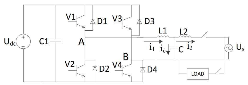
The simplified diagram of the DC/AC stage of a single-phase photovoltaic inverter system is shown in Figure 1. The solar inverter uses current control.Based on circuit theory, the system vector diagram is shown in Figure 2.The operating state of the solar inverter can be summarized into the following three cases:
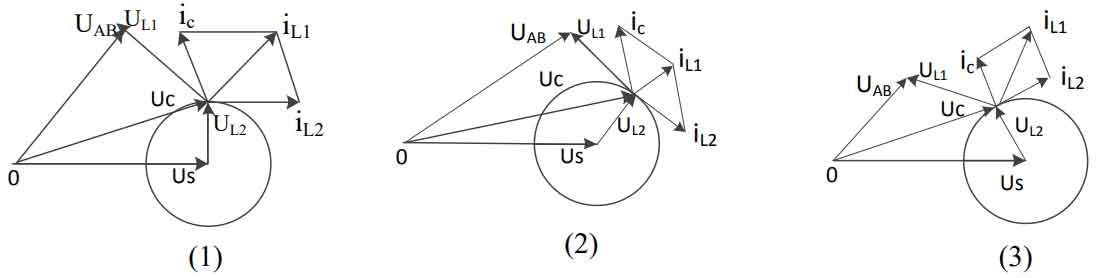
(1) The frequency and phase of the current iL2 integrated into the grid are consistent with the grid voltage Us, and the system outputs all active power.
(2) The phase of the current iL2 that is connected to the grid lags behind the grid voltage Us, and the system provides inductive reactive power.
(3) The phase of the current iL2 integrated into the grid leads the grid voltage Us, and the system provides capacitive reactive power.
Therefore, by controlling the phase of the grid-connected current, the solar inverter can provide both a certain amount of active power for the grid and a portion of reactive power for compensation, achieving the effect of a power compensator.
1.2 Control principle of the system
The input and output power of the solar inverter are balanced, and the bus voltage can be indirectly stabilized through the control of the active component of the grid-connected current.The active command current is obtained from the output of the voltage outer loop controller, the reactive command current is obtained from the detection current of the load, and the grid-connected command current is composed of the two.Through the dual closed-loop control mentioned earlier, it is possible to achieve reactive compensation for the load and feed the grid with active energy.The power regulation block diagram of the solar inverter is shown in Figure 3.
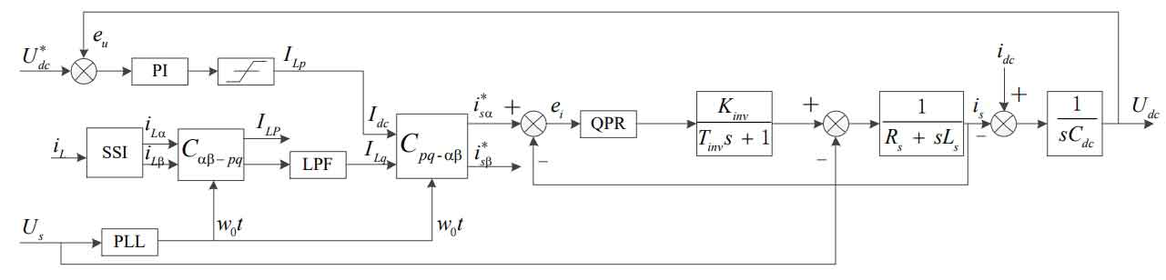
The block diagram in Figure 3 includes single-phase reactive current detection, voltage control outer loop, and current control inner loop.Rs is the grid equivalent series resistance, Ts is the system switching period, Kinv is the gain of the solar inverter, idc is the boost converter output current, is is the solar inverter output current, iL is the load output current, U*dc is the bus reference voltage, i*s is the reference current, eu is the error of the voltage outer loop, and Us is the grid voltage.
2. Improved reactive power compensation control strategy
2.1 Construction of two-phase orthogonal current
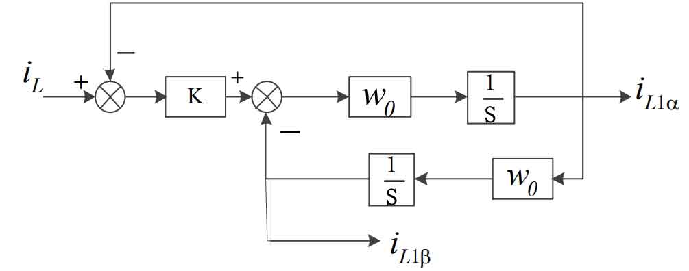
In order to obtain the magnitude of the reactive current at the grid-connected side load, the theory of instantaneous reactive power is extended to single-phase systems for application, requiring the construction of a virtual two-phase orthogonal current.This design proposes a method for constructing a two-phase orthogonal current that can overcome the time delay problem in traditional phase-shift detection. It is mainly generated by a sinusoidal signal integrator as shown in Figure 4.
The closed-loop transfer function in Figure 4 is expressed as:
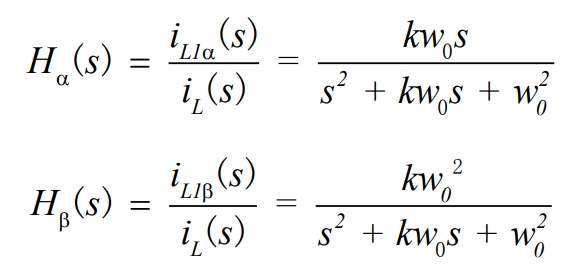
The phase angle in the formula has the following relationship:
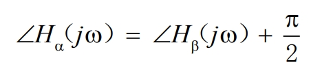
By using a sine signal integrator, a sinusoidal signal with the same amplitude and a phase difference of 90 degrees is output.In steady state, |Hα| = |Hβ| =1, indicating that the system can achieve zero static error tracking for the part of the input signal with frequency w0.This property can be used to obtain the fundamental component of load current reactive compensation.The value of k in the equation affects the bandwidth of the closed-loop system. When k changes, the closed-loop transfer function of the proposed structure closed-loop is shown in Figure 5(a) and 5(b) as a Bode plot and step response.
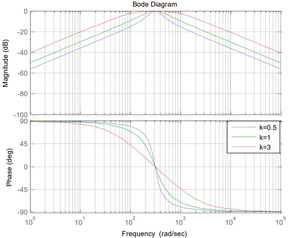
By using the proposed sinusoidal signal integrator to perform notch filtering at the fundamental frequency w0, the input current iL can be filtered to obtain two-phase orthogonal currents iL1α and iL1β.From the simulation curve, it can be seen that when k decreases, the system’s bandwidth decreases and the filtering performance improves, but the system’s dynamic response slows down. As shown in Figure 5(b), k=0.7 is selected for the experiment.From Figure 5(a), it can be seen that there is no attenuation of the input signal at the notch frequency, but there is significant attenuation near the notch frequency.Therefore, this method has the following advantages: (1) generating orthogonal two-phase currents, and (2) performing delay-free filtering on orthogonal current signals.
The discretization of the sine signal integrator has a significant impact on its stability.Common methods for obtaining discrete time integration include Euler’s method for the previous term, Euler’s method for the next term, and bilinear transformation.However, the integration using Euler’s method cannot produce the desired 90-degree phase shift, resulting in the output current signal not being exactly orthogonal and not meeting the control requirements.Therefore, this article chooses bilinear transformation.
The integral equation for the bilinear transformation is as follows:
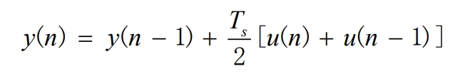
Therefore, the discrete domain expression of 1/s is:
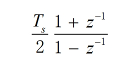
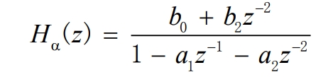
Substituting s with a formula, the closed-loop transfer function (Hd(s)) is discretized using the bilinear transformation method to obtain:
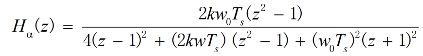
Let x=2kw0Ts and y=(w0Ts)^2 to obtain the standardized equation of the formula:
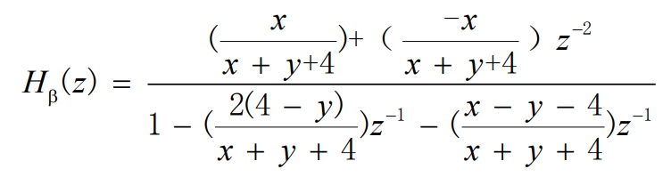
The simplified form of the formula is obtained:
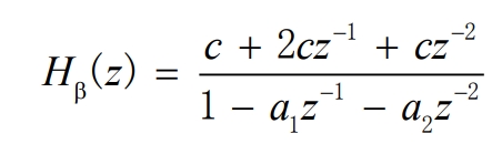
Similarly, the closed-loop transfer function (Hβ(s)) is bilinearly transformed to obtain:
2.2 Acquisition of grid voltage synchronization signal
Not only is it necessary to obtain a grid voltage synchronization signal sinωt in the control of instantaneous active components of single-phase grid-connected currents to ensure that the frequency and phase of the output current and grid voltage signals are consistent, but the grid voltage synchronization signal is also required for instantaneous reactive current detection.Therefore, obtaining an accurate grid voltage synchronization signal is crucial, and scholars have proposed a number of methods for obtaining synchronized voltage signals.
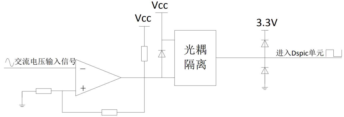
The most commonly used method in engineering is to obtain the grid voltage synchronization signal through hardware zero-crossing phase lock, as shown in Figure 6.The AC voltage signal is passed through a zero-crossing comparator to obtain a square wave signal with the same frequency as the grid voltage, and then passed through a first-level optocoupler isolation circuit to send the signal to the cap unit of the processor. The cap unit generates an interrupt at the moment of capturing the zero crossing point and performs phase lock counting.The biggest advantage of this method is that the hardware circuit is simple and easy to implement in software.Therefore, this design uses this zero-crossing detection method combined with software filtering.The grid frequency deviation is generally between ±0.2Hz. The difference in counting between the two input captures generated by the cap unit is calculated. If it is much smaller than the difference in counting between the grid power frequency cycles, and it does not occur more than three times in a row, it is considered to be a capture interrupt caused by interference, and the interrupt returns.
2.3 Control of grid-connected current
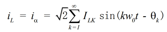
Suppose the load current signal at the point of common coupling (PCC) is:
Where, ω0 represents the power frequency of the grid-connected voltage;θk represents the phase shift of the current component with harmonic order k;and ILK represents the effective value of the current component with harmonic order k.
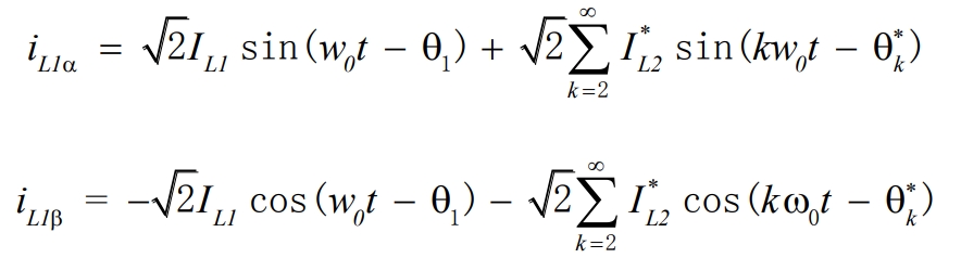
By controlling the sine signal integrator, the two-phase virtual orthogonal currents output by the constructed load are:
Wherein, I*L2 and θ*k are the effective current value and phase shift of the load harmonic current after the action of the controller.
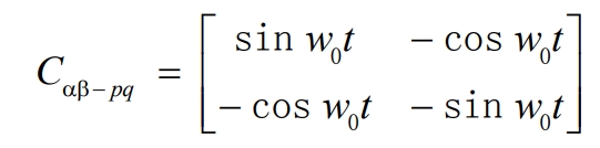
By using a phase-locked loop, the fundamental sine signal V1α = sin w0t and the cosine signal V1β = cos w0t of the grid voltage can be obtained.Through the Park transformation, we obtain:
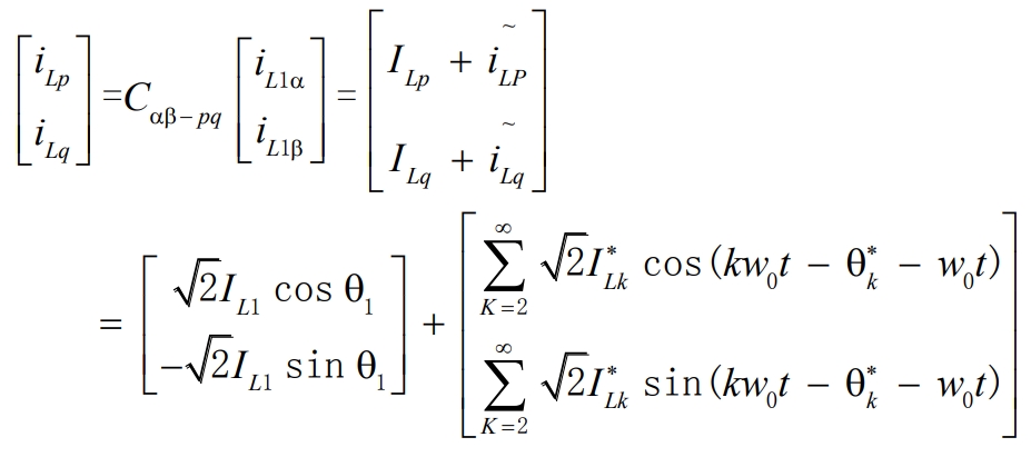
Among them:
According to the instantaneous reactive power theory, ILp in the formula is the DC component of the load active current, and ILq is the DC component of the load reactive current.By using a low-pass filter to filter out the AC components of the load active and reactive currents, the DC component of the reactive current can be separated.
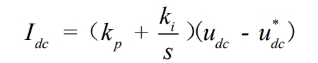
As analyzed, in order to stabilize the bus voltage, a PI regulator is used, with the input being the difference between the given DC voltage u*dc and the current bus voltage udc.The active reference current is output by the PI controller and has a magnitude Idc as follows:
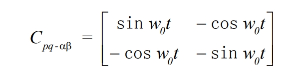
To obtain the grid-connected command current, it is necessary to perform inverse coordinate transformation on the active reference current Idc and the load’s reactive current component ILq:
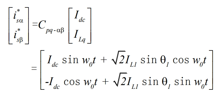
Of which:
After obtaining the grid reference current, performing closed-loop control according to the control method for the current inner loop in Chapter 2 can achieve the goal of reactive and active power control, allowing the solar inverter to simultaneously output both active and specified reactive power.
3. Summary
Analyzing the principle of single-phase reactive power compensation, a reference current generation method based on a sinusoidal signal integrator is proposed to construct a virtual two-phase current, which overcomes the problem of phase delay in constructing a virtual phase current in traditional methods.The sinusoidal signal integrator is discretized using bilinear transformation to ensure that the dynamic performance of the controller is not affected.By using the harmonic current detection ip-iq method, the reactive component of the load is separated, and the active and reactive given values of the reference current are obtained. The active control and reactive compensation of the solar inverter are achieved using a double closed-loop control, achieving the effect of a power compensator.