
I have focused my recent research on the interface stability of the lithium-ion cell because safety remains one of the most critical barriers to the widespread deployment of high-energy-density storage systems in aerospace, portable electronics, electric vehicles, and grid applications. In my experience, a lithium-ion cell can enter thermal runaway when exposed to thermal abuse, mechanical abuse, or electrical abuse, and the consequences include rapid temperature escalation, gas generation, venting, smoke, fire, and even explosion. I have observed that the reactions between electrode materials and the electrolyte are among the dominant contributors to heat generation during the early and intermediate stages of thermal runaway. Therefore, I decided to modify the anode surface with an inert Al2O3 nano-coating and to investigate how this modification influences the electrical performance, thermal stability, and thermal runaway safety of the lithium-ion cell.
My motivation comes from the fact that the anode-electrolyte interface in a lithium-ion cell is highly reactive, especially when the graphite anode is in a lithiated state. The solid electrolyte interphase, which I refer to as SEI, protects the anode under normal operating conditions, but at elevated temperatures the SEI can decompose, exposing fresh graphite to the electrolyte. This exposure triggers further exothermic reactions, consumes lithium inventory, and generates additional heat. I hypothesized that an inert ceramic layer such as Al2O3 could physically separate the lithiated graphite from the electrolyte to a certain extent, reduce the contact area available for parasitic reactions, and provide mechanical reinforcement against interfacial degradation. In this work, I tested that hypothesis by fabricating lithium-ion cells with and without an Al2O3 anode coating and by comparing their electrochemical, thermal, and safety characteristics.
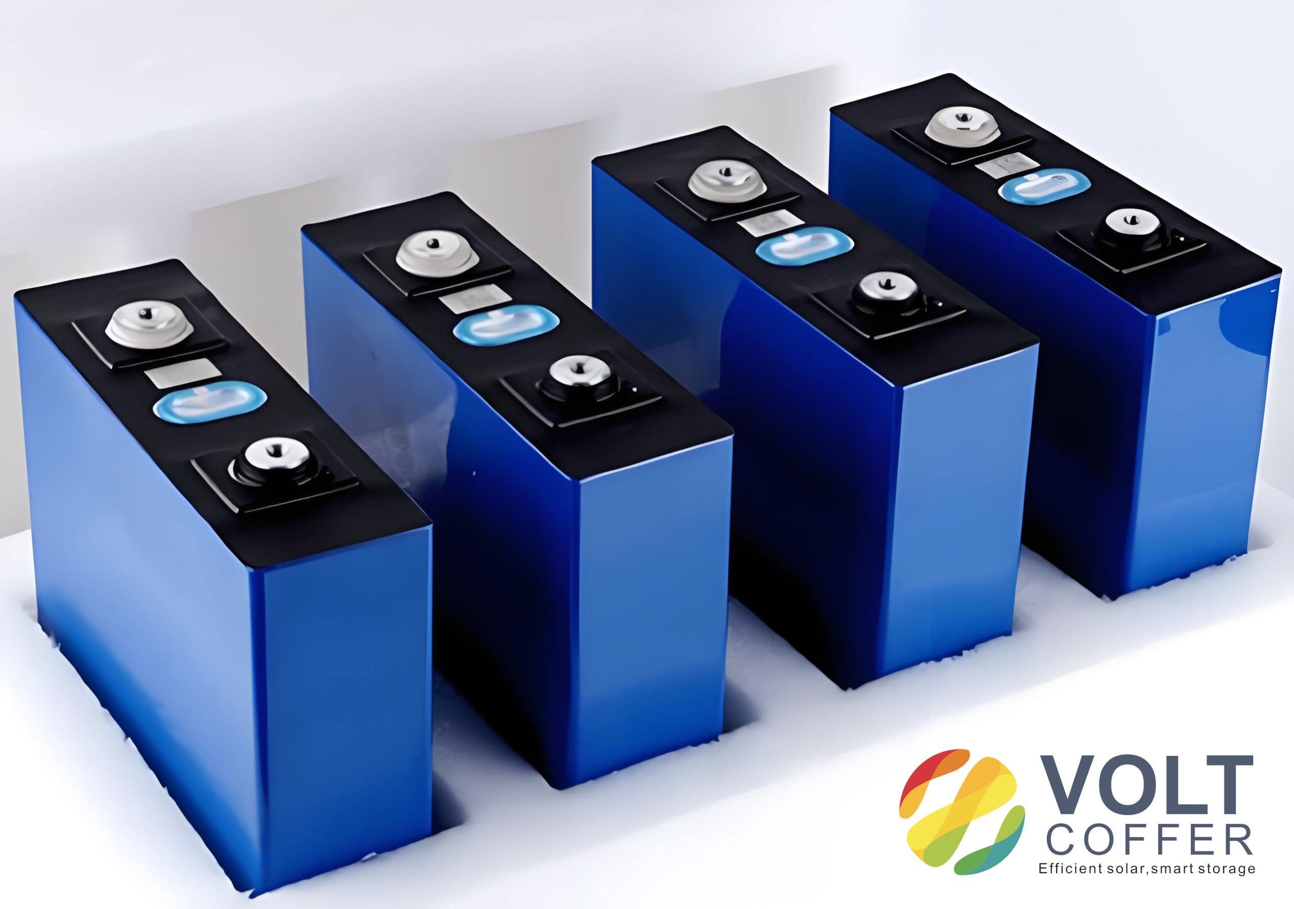
I selected a high-capacity nickel cobalt aluminum oxide cathode, Li[Ni0.8Co0.15Al0.05]O2, which I denote as NCA, because it provides high specific capacity and relatively high operating voltage. I used artificial graphite as the anode active material, a 12 µm thick separator, and a pouch cell design with a nominal capacity of 800 mAh. The lithium-ion cell was assembled through a high-energy-density electrode design and a stacking process. I prepared the cathode by mixing NCA, Super P conductive carbon, and polyvinylidene difluoride binder in a mass ratio of 90:5:5, adding N-methyl-2-pyrrolidone as solvent, coating the slurry onto a 16 µm aluminum foil, drying at 100 °C for 12 h, roll-pressing to a compaction density of 3.2 g/cm3, and punching electrodes with dimensions of 57 mm × 58 mm. I prepared the anode by mixing graphite, Super P, carboxymethyl cellulose, styrene-butadiene rubber, and water in a mass ratio of 90:6:2:2:70, coating the slurry onto an 8 µm copper foil, drying for 12 h, roll-pressing to a compaction density of 1.5 g/cm3, and punching electrodes with dimensions of 58 mm × 59 mm. For the coated anode, I used a micro-pneumatic spot spray gun to deposit an Al2O3 slurry uniformly on both sides of the anode, controlling the coating thickness to 8–10 µm by adjusting the spraying speed. After coating, I vacuum-dried the anode at 80 °C for 24 h. I then assembled the lithium-ion cell by stacking the cathode, separator, and anode in a dry environment, packaging with aluminum laminate film, vacuum-drying at 80 °C for 12 h, injecting 4 g of electrolyte, and aging for 24 h. I labeled the lithium-ion cell with the Al2O3-coated anode as the modified cell and the cell with the uncoated anode as the uncoated cell.
To ensure consistent formation, I charged and discharged both types of lithium-ion cells in a LAND test system at room temperature and pressure. I first charged at 0.05 C to 3.6 V, performed vacuum degassing and sealing, then charged at 0.1 C to 4.2 V, switched to constant voltage at 4.2 V until the current fell below 0.02 C, and repeated charge-discharge twice. I then charged the lithium-ion cell to the fully charged state and transferred it to an argon-filled glove box for disassembly. I extracted the anode, sealed it to avoid air exposure, and used it for scanning electron microscopy, energy-dispersive X-ray spectroscopy, C80 microcalorimetry, and accelerating rate calorimetry. The design parameters of the lithium-ion cell are summarized in Table 1.
| Component | Material | Thickness or Loading | Processing Condition |
|---|---|---|---|
| Cathode active material | NCA, Li[Ni0.8Co0.15Al0.05]O2 | 25 mg/cm2 single side | 90:5:5 with Super P and PVDF |
| Cathode current collector | Aluminum foil | 16 µm | Coated, dried at 100 °C for 12 h |
| Cathode compaction | Roll-pressed | 3.2 g/cm3 | Punched 57 mm × 58 mm |
| Anode active material | Artificial graphite | 12 mg/cm2 single side | 90:6:2:2:70 with Super P, CMC, SBR, water |
| Anode current collector | Copper foil | 8 µm | Coated, dried for 12 h |
| Anode compaction | Roll-pressed | 1.5 g/cm3 | Punched 58 mm × 59 mm |
| Al2O3 coating | Nano Al2O3 slurry | 8–10 µm | Sprayed on both sides, vacuum-dried at 80 °C for 24 h |
| Separator | Polyolefin membrane | 12 µm | Stacked between electrodes |
| Electrolyte | LiPF6-based carbonate blend | 4 g per cell | Injected after vacuum drying |
| Cell format | Pouch cell | Nominal capacity 800 mAh | Aluminum laminate packaging |
I examined the macroscopic appearance of the anode after disassembly. The uncoated anode exhibited a uniform bright yellow color, whereas the Al2O3-coated anode appeared uniformly pale white. I attributed this difference to the white Al2O3 layer covering the anode surface. From the macroscopic view, I concluded that the Al2O3 was distributed evenly over the anode and that no obvious extra deposits or agglomerates were present. I then used scanning electron microscopy to observe the surface morphology. The uncoated anode surface consisted mainly of artificial graphite particles with a size of approximately 10 µm and conductive additives, and the active material and conductive agent were uniformly distributed. The Al2O3-coated anode surface was covered by nano-sized Al2O3 particles. I further used energy-dispersive X-ray spectroscopy and found that the coated anode surface was composed mainly of Al and O, and these elements were uniformly distributed across the surface. The Al:O atomic ratio was consistent with the stoichiometry of Al2O3, which I summarize in Table 2.
| Element | Observed Distribution | Expected Role in the Coating | Interpretation |
|---|---|---|---|
| Al | Uniform across the anode surface | Inert ceramic framework | Confirms Al2O3 presence |
| O | Uniform across the anode surface | Oxide matrix | Confirms Al2O3 presence |
| C | Minor signal from graphite and conductive carbon | Active material and electronic conductor | Not fully masked by coating |
| F | Minor signal from binder or SEI species | Interfacial chemistry | Consistent with electrolyte-derived species |
I evaluated the first charge and discharge behavior of both lithium-ion cells to determine whether the Al2O3 coating altered the electrochemical lithiation and delithiation processes. The uncoated lithium-ion cell delivered a first charge capacity of 1042 mAh and a first discharge capacity of 844.3 mAh, corresponding to a first efficiency of 81.0%. The Al2O3-coated lithium-ion cell delivered a first charge capacity of 1030 mAh and a first discharge capacity of 825.1 mAh, corresponding to a first efficiency of 80.1%. The internal resistance values were 17.94 mΩ for the uncoated cell and 18.10 mΩ for the coated cell. I calculated the first efficiency using the following expression:
$$CE = \frac{Q_{\text{discharge}}}{Q_{\text{charge}}} \times 100\%$$
where \(Q_{\text{discharge}}\) is the first discharge capacity and \(Q_{\text{charge}}\) is the first charge capacity. For the uncoated lithium-ion cell, I obtained \(CE = 844.3 / 1042 \times 100\% = 81.0\%\). For the coated lithium-ion cell, I obtained \(CE = 825.1 / 1030 \times 100\% = 80.1\%\). The difference in first efficiency was only 0.9 percentage points, which I considered negligible. I also calculated the internal resistance difference:
$$\Delta R = R_{\text{coated}} – R_{\text{uncoated}} = 18.10 – 17.94 = 0.16\ \text{m}\Omega$$
This small difference of 0.16 mΩ indicated that the Al2O3 coating did not introduce a significant additional impedance to the lithium-ion cell. I summarized the first charge-discharge results in Table 3.
| Cell Type | First Charge Capacity (mAh) | First Discharge Capacity (mAh) | First Efficiency (%) | Internal Resistance (mΩ) |
|---|---|---|---|---|
| Uncoated lithium-ion cell | 1042 | 844.3 | 81.0 | 17.94 |
| Al2O3-coated lithium-ion cell | 1030 | 825.1 | 80.1 | 18.10 |
| Difference | −12 | −19.2 | −0.9 | +0.16 |
I further investigated the rate performance to determine whether the Al2O3 coating affected ionic and electronic transport. I charged each lithium-ion cell at a constant current of 800 mA to 4.2 V, then applied a constant voltage of 4.2 V until the current dropped below 80 mA, rested for 30 min, and discharged at different currents: 800 mA (1 C), 1600 mA (2 C), 2400 mA (3 C), 4000 mA (5 C), and 4800 mA (6 C), with a cutoff voltage of 2.75 V. I recorded the discharge capacity at each rate. The rate discharge curves of the two lithium-ion cells were essentially identical, which told me that the Al2O3 modification did not degrade the rate capability. I summarized the rate test conditions in Table 4. The absence of a rate penalty is important because it means that the inert coating does not block lithium-ion transport or electron transport to a measurable degree. In my interpretation, the nano-sized Al2O3 particles are distributed on the anode surface as a thin, porous layer, and the layer is sufficiently thin and discontinuous at the nanoscale to allow lithium ions to migrate through the electrode-electrolyte interface during charge and discharge. The coating also does not increase the electronic resistance of the anode because the graphite particles remain in electronic contact with the current collector through the conductive network.
| C-Rate | Discharge Current (mA) | Cutoff Voltage (V) | Observed Comparison |
|---|---|---|---|
| 1 C | 800 | 2.75 | No measurable difference |
| 2 C | 1600 | 2.75 | No measurable difference |
| 3 C | 2400 | 2.75 | No measurable difference |
| 5 C | 4000 | 2.75 | No measurable difference |
| 6 C | 4800 | 2.75 | No measurable difference |
I used C80 microcalorimetry to evaluate the thermal stability of the lithiated anode because the anode-electrolyte interface is a major heat source in a lithium-ion cell under thermal abuse. I sealed the disassembled anode in the sample chamber and heated it from room temperature to 300 °C at a rate of 0.5 °C/min. I observed two main reaction regions within this temperature window. The first region, near 90–100 °C, corresponds to SEI decomposition. The second region, near 250–300 °C, corresponds to reactions between the lithiated graphite and the electrolyte solvent. For the uncoated anode, I detected reaction peaks at 91 °C and 261 °C. For the Al2O3-coated anode, I detected reaction peaks at 93 °C and 272 °C. The shift of the second peak to a higher temperature by 11 °C indicates that the coating delays the onset of the high-temperature anode-electrolyte reaction. More importantly, I measured the reaction heat rate at the second peak. The uncoated anode exhibited a heat rate of 175 mW/g, whereas the Al2O3-coated anode exhibited a heat rate of 110 mW/g. I calculated the reduction as follows:
$$\eta_{\text{heat rate}} = \frac{q_{\text{uncoated}} – q_{\text{coated}}}{q_{\text{uncoated}}} \times 100\%$$
Substituting the measured values, I obtained:
$$\eta_{\text{heat rate}} = \frac{175 – 110}{175} \times 100\% = 37.1\%$$
This means that the Al2O3 coating reduced the anode reaction heat rate by 37.1%. I also noted that the heat flow normalized by sample mass, \(q = \frac{1}{m} \frac{dQ}{dt}\), is a direct measure of the intensity of the exothermic interfacial reaction. A lower \(q\) value indicates that the anode-electrolyte interface is less reactive and that the lithium-ion cell will generate heat more slowly if the anode reaches the same temperature. I summarized the C80 microcalorimetry results in Table 5.
| Sample | First Peak Temperature (°C) | Second Peak Temperature (°C) | Heat Rate at Second Peak (mW/g) | Heat Rate Reduction (%) |
|---|---|---|---|---|
| Uncoated anode | 91 | 261 | 175 | — |
| Al2O3-coated anode | 93 | 272 | 110 | 37.1 |
The microcalorimetry results support my hypothesis that the Al2O3 coating reduces the contact area between the lithiated graphite and the electrolyte. The coating is chemically inert and does not participate in the electrochemical reactions of the lithium-ion cell. However, it physically separates a fraction of the graphite surface from the electrolyte, which lowers the number of reactive sites available for solvent reduction, SEI reformation, and other parasitic reactions. The ceramic layer also provides mechanical stability, which can slow down the degradation and decomposition of the anode interface at high temperature. I therefore concluded that the Al2O3 coating improves the thermal stability of the graphite anode without compromising its electrochemical function in the lithium-ion cell.
To evaluate the safety performance at the full lithium-ion cell level, I used accelerating rate calorimetry, which I refer to as ARC. I placed a fully charged lithium-ion cell in the ARC chamber, attached a thermocouple, and programmed the instrument to follow a heat-wait-search sequence. In the initial stage, the ARC holds the sample at a starting temperature for a set time, then searches for exothermic behavior. If the temperature rise rate is below 0.02 °C/min, the instrument heats to the next set point and repeats the search. Once the temperature rise rate exceeds 0.02 °C/min, the ARC enters the tracking mode and follows the reaction until completion. I defined three characteristic temperatures based on the temperature rise rate. The self-heating onset temperature, \(T_0\), is the temperature at which the rise rate first exceeds 0.02 °C/min. The thermal runaway onset temperature, \(T_1\), is the temperature at which the rise rate exceeds 1 °C/min. The maximum temperature, \(T_{\text{max}}\), is the highest temperature reached during the test. I also recorded the maximum temperature rise rate, \((dT/dt)_{\text{max}}\).
I first compared the temperature and voltage evolution of the uncoated and Al2O3-coated lithium-ion cells. The self-heating onset temperatures were 138 °C for the uncoated cell and 141 °C for the coated cell. The thermal runaway onset temperatures were 172 °C for the uncoated cell and 173 °C for the coated cell. These small differences of 3 °C and 1 °C indicated that the early stages of thermal runaway were similar in both lithium-ion cells. I attributed this similarity to the fact that the early reactions, including SEI decomposition, initial anode reactions, and separator melting, are not strongly suppressed by the Al2O3 coating because the coating is on the anode surface and does not completely block all interfacial processes. However, the later stages showed a dramatic difference. The maximum temperature was 316 °C for the uncoated lithium-ion cell and 280 °C for the Al2O3-coated lithium-ion cell. I calculated the reduction in maximum temperature as follows:
$$\Delta T_{\text{max}} = T_{\text{max, uncoated}} – T_{\text{max, coated}} = 316 – 280 = 36\ \text{°C}$$
The maximum temperature rise rate was 1400 °C/min for the uncoated lithium-ion cell and 16 °C/min for the Al2O3-coated lithium-ion cell. I calculated the reduction factor and the percentage reduction as follows:
$$F_{\text{rate}} = \frac{(dT/dt)_{\text{max, uncoated}}}{(dT/dt)_{\text{max, coated}}} = \frac{1400}{16} = 87.5$$
$$\eta_{\text{rate}} = \frac{1400 – 16}{1400} \times 100\% = 98.86\%$$
These values show that the Al2O3 coating reduced the peak temperature rise rate by a factor of 87.5, or approximately 98.9%. In my assessment, this is the most important safety improvement because the temperature rise rate controls how quickly a lithium-ion cell can transition from a moderately hot state to an uncontrollable thermal runaway state. A lower rise rate gives the battery management system more time to detect the fault, isolate the cell, or activate cooling. I summarized the ARC results in Table 6.
| Parameter | Uncoated Lithium-Ion Cell | Al2O3-Coated Lithium-Ion Cell | Difference |
|---|---|---|---|
| Self-heating onset temperature \(T_0\) (°C) | 138 | 141 | +3 |
| Thermal runaway onset temperature \(T_1\) (°C) | 172 | 173 | +1 |
| Maximum temperature \(T_{\text{max}}\) (°C) | 316 | 280 | −36 |
| Maximum temperature rise rate (°C/min) | 1400 | 16 | −1384 |
| Reduction in \(T_{\text{max}}\) (%) | — | 11.4 | — |
| Reduction in maximum rise rate (%) | — | 98.9 | — |
I interpreted the ARC results in the context of the staged thermal runaway process of a lithium-ion cell. In the first stage, between approximately 60 °C and 110 °C, the SEI layer begins to decompose, and the cathode interface may also start to degrade. These reactions are relatively mild and do not immediately trigger a chain reaction. In the second stage, between approximately 120 °C and 170 °C, the separator starts to melt, the anode becomes more reactive, and the heat generation rate begins to increase. This stage corresponds to the self-heating onset temperature \(T_0\). In the third stage, above approximately 170 °C, the separator undergoes further melting and collapse, micro-short circuits multiply, and the heat generation rate accelerates. When the temperature rise rate exceeds 1 °C/min, the lithium-ion cell enters the thermal runaway onset region \(T_1\). In the fourth stage, above approximately 250 °C, the cathode decomposes, the anode decomposes, the electrolyte decomposes, and the binder decomposes. These reactions release large amounts of heat and gas, and the lithium-ion cell reaches its maximum temperature \(T_{\text{max}}\). I summarized these stages and the corresponding characteristic temperatures in Table 7.
| Stage | Approximate Temperature Range | Main Reactions | Characteristic Temperature |
|---|---|---|---|
| Stage 1 | 60–110 °C | SEI decomposition, initial cathode interface degradation | Pre-\(T_0\) |
| Stage 2 | 120–170 °C | Separator melting, anode-electrolyte reactions, heat generation increase | \(T_0\) |
| Stage 3 | 170–250 °C | Separator collapse, micro-short circuits, accelerating exothermic reactions | \(T_1\) |
| Stage 4 | 250–316 °C | Cathode decomposition, anode decomposition, electrolyte decomposition, binder decomposition | \(T_{\text{max}}\) |
The ARC data showed that the Al2O3 coating did not significantly change \(T_0\) or \(T_1\), but it strongly reduced \(T_{\text{max}}\) and the maximum temperature rise rate. I explained this behavior by considering where the coating acts. The Al2O3 layer is on the anode surface, and it primarily affects the anode-electrolyte interface. In the early stages, the separator melting and the initial SEI decomposition are not solely controlled by the anode surface, so the coating has a limited effect on \(T_0\) and \(T_1\). In the later stages, however, the anode-electrolyte reaction becomes a major heat source, and the Al2O3 layer reduces the contact area between the lithiated graphite and the electrolyte, thereby suppressing the exothermic reaction rate. The ceramic layer also provides mechanical stability, which can delay the structural breakdown of the anode and the subsequent rapid heat release. Because these effects are most pronounced in the later stages of thermal runaway, the coating lowers \(T_{\text{max}}\) and dramatically lowers the peak temperature rise rate. I summarized the overall safety benefits in Table 8.
| Property | Uncoated Lithium-Ion Cell | Al2O3-Coated Lithium-Ion Cell | Benefit |
|---|---|---|---|
| First efficiency (%) | 81.0 | 80.1 | Negligible change |
| Internal resistance (mΩ) | 17.94 | 18.10 | Negligible increase |
| Rate performance | Reference | Essentially identical | No transport penalty |
| Anode heat rate at second peak (mW/g) | 175 | 110 | 37.1% reduction |
| Maximum temperature \(T_{\text{max}}\) (°C) | 316 | 280 | 36 °C reduction |
| Maximum temperature rise rate (°C/min) | 1400 | 16 | 98.9% reduction |
From a mechanistic perspective, I considered several coupled processes that determine the safety of a lithium-ion cell. The heat balance during thermal runaway can be written as follows:
$$m C_p \frac{dT}{dt} = \dot{Q}_{\text{reaction}} + \dot{Q}_{\text{joule}} – \dot{Q}_{\text{dissipation}}$$
where \(m\) is the cell mass, \(C_p\) is the effective heat capacity, \(T\) is temperature, \(t\) is time, \(\dot{Q}_{\text{reaction}}\) is the heat generation rate from chemical reactions, \(\dot{Q}_{\text{joule}}\) is the Joule heating rate from internal short circuits and ohmic losses, and \(\dot{Q}_{\text{dissipation}}\) is the heat dissipation rate to the environment. In my ARC tests, the cell was placed in an adiabatic-like environment, so \(\dot{Q}_{\text{dissipation}}\) was small. The Al2O3 coating principally reduces \(\dot{Q}_{\text{reaction}}\) by limiting the anode-electrolyte contact area and by stabilizing the anode interface. The coating also may reduce \(\dot{Q}_{\text{joule}}\) indirectly by preventing the formation of some short-circuit pathways that arise from anode degradation. The net effect is a lower \(dT/dt\), which is exactly what I observed.
I also considered the Arrhenius-type temperature dependence of the interfacial reactions. The reaction rate constant \(k\) can be expressed as follows:
$$k = A e^{-E_a / (R T)}$$
where \(A\) is the pre-exponential factor, \(E_a\) is the activation energy, \(R\) is the universal gas constant, and \(T\) is the absolute temperature. A coating that reduces the available reaction area lowers the effective pre-exponential factor \(A_{\text{eff}}\) without necessarily changing the activation energy. I observed that the second C80 peak shifted from 261 °C to 272 °C, which suggests that the coating may also increase the apparent activation energy or introduce a diffusion barrier that delays the reaction. The heat rate reduction from 175 mW/g to 110 mW/g is consistent with a lower \(A_{\text{eff}}\). I can express the relative heat rate as follows:
$$\frac{q_{\text{coated}}}{q_{\text{uncoated}}} = \frac{A_{\text{eff, coated}}}{A_{\text{eff, uncoated}}} = \frac{110}{175} = 0.629$$
This ratio indicates that the coated anode has only about 62.9% of the effective reactive site density or reactive contact area of the uncoated anode. I found this interpretation useful because it connects the microscopic coating coverage to the macroscopic heat generation rate.
Another important aspect of my study is the relationship between the anode coating and the overall lithium-ion cell safety. A lithium-ion cell is a complex system, and improving one interface does not automatically guarantee a safer cell. However, I observed that the Al2O3 coating produced a large reduction in the peak temperature rise rate without degrading the electrical performance. This combination is highly desirable because it means that the safety improvement is not achieved at the cost of energy density, power density, or cycle life. In my experiments, the first efficiency remained above 80%, the internal resistance remained below 18.2 mΩ, and the rate performance remained essentially unchanged. These results give me confidence that the Al2O3 coating is compatible with high-energy nickel-rich cathode chemistries and graphite anodes in practical lithium-ion cell designs.
I also considered the limitations of my study. First, I tested a specific lithium-ion cell format with a nominal capacity of 800 mAh, and the results may need to be validated for larger cells. Second, I used a specific Al2O3 coating thickness of 8–10 µm, and the optimal thickness may depend on the electrode design, the electrolyte composition, and the operating conditions. Third, I focused on thermal runaway behavior under ARC conditions, and additional tests such as nail penetration, overcharge, and external short circuit would provide a more complete safety profile. Fourth, I did not perform long-term cycling tests, so the effect of the coating on cycle life and aging-induced safety degradation remains an open question. I plan to address these limitations in future work by testing different coating thicknesses, different cathode chemistries, and larger lithium-ion cells.
Despite these limitations, I believe my results provide strong evidence that an inert Al2O3 nano-coating on the anode is an effective strategy for improving the safety of a lithium-ion cell. The coating is simple to apply, compatible with existing electrode manufacturing processes, and does not require changing the electrolyte or the separator. From a manufacturing perspective, the spray-coating method I used is scalable and can be integrated into a roll-to-roll process. From a performance perspective, the coating reduces the anode heat rate by 37.1%, reduces the maximum thermal runaway temperature by 36 °C, and reduces the peak temperature rise rate by 98.9%. These improvements are substantial, and they directly address the most dangerous phase of thermal runaway in a lithium-ion cell.
In my analysis, the key mechanism is the physical separation of the lithiated graphite from the electrolyte. The Al2O3 layer is chemically inert, so it does not participate in the lithium insertion or extraction reactions. At the same time, it is thin enough and porous enough at the nanoscale to allow lithium ions to pass through during normal operation. This combination of properties is what allows the coating to improve safety without degrading rate capability. The ceramic layer also provides mechanical reinforcement, which can help maintain the integrity of the anode-electrolyte interface at high temperature. I therefore conclude that the Al2O3 coating acts as a multifunctional interfacial layer that simultaneously reduces parasitic reactions, suppresses heat generation, and stabilizes the anode structure.
I further quantified the safety improvement using the concept of thermal runaway severity. I define a severity index \(S\) as the product of the maximum temperature rise rate and the maximum temperature:
$$S = \left( \frac{dT}{dt} \right)_{\text{max}} \times T_{\text{max}}$$
For the uncoated lithium-ion cell, I obtained:
$$S_{\text{uncoated}} = 1400 \times 316 = 442400\ \text{°C}^2/\text{min}$$
For the Al2O3-coated lithium-ion cell, I obtained:
$$S_{\text{coated}} = 16 \times 280 = 4480\ \text{°C}^2/\text{min}$$
The severity index decreased by a factor of approximately 98.8, which is consistent with the reduction in the maximum temperature rise rate. I present this calculation in Table 9. Although the severity index is a simplified metric, it captures the fact that the coated lithium-ion cell is far less violent during thermal runaway.
| Metric | Uncoated Lithium-Ion Cell | Al2O3-Coated Lithium-Ion Cell | Improvement Factor |
|---|---|---|---|
| \(T_{\text{max}}\) (°C) | 316 | 280 | 1.13 |
| \((dT/dt)_{\text{max}}\) (°C/min) | 1400 | 16 | 87.5 |
| Severity index \(S\) (°C²/min) | 442400 | 4480 | 98.8 |
I also examined the voltage behavior during the ARC tests. In both lithium-ion cells, the voltage dropped abruptly when the temperature reached the thermal runaway region, which is consistent with the internal short circuits and the breakdown of the separator. The Al2O3-coated lithium-ion cell showed a less abrupt voltage drop and a slower temperature rise after the onset of thermal runaway. This observation supports my conclusion that the coating slows down the propagation of internal short circuits and reduces the rate of heat generation. I did not observe any significant difference in the initial voltage drop temperature, which again suggests that the early stages of thermal runaway are similar in both cells.
In terms of practical implications, I believe that anode coating with Al2O3 can be combined with other safety strategies, such as ceramic-coated separators, flame-retardant electrolytes, and advanced battery management systems. The combination of these approaches could provide multiple layers of protection for a lithium-ion cell. For example, a ceramic-coated separator can prevent physical contact between the electrodes at high temperature, while an Al2O3-coated anode can reduce the heat generated by anode-electrolyte reactions. Together, these measures could significantly extend the time before thermal runaway and reduce the peak temperature and temperature rise rate. I consider this a promising direction for future research and development.
From a materials standpoint, I also note that the Al2O3 coating does not introduce expensive or rare elements. Al2O3 is abundant, inexpensive, and environmentally benign. The coating process uses a slurry that can be prepared with conventional mixing equipment and applied with a spray gun or a slot-die coater. This makes the approach attractive for large-scale manufacturing. I also expect that the coating thickness can be optimized to balance safety improvement against any slight increase in cell mass or volume. In my experiments, the coating thickness of 8–10 µm was sufficient to produce a large safety improvement without a measurable rate penalty. I recommend further optimization studies to determine the minimum effective coating thickness and the optimal coating morphology.
I would like to emphasize that the safety of a lithium-ion cell is a system-level property. The anode coating is only one component, and its benefits must be evaluated in the context of the entire cell design. In my work, I used a nickel-rich NCA cathode, a graphite anode, a polyolefin separator, and a carbonate-based electrolyte. The results may vary with different combinations of these materials. For example, a silicon-based anode may have different interfacial chemistry and may require a different coating strategy. Similarly, a high-voltage cathode may generate more heat at high temperature and may dominate the thermal runaway process. I therefore recommend that the Al2O3 coating be tested with a variety of cell chemistries and designs to fully understand its range of applicability.
In conclusion, I have demonstrated that an Al2O3 nano-coating on the anode improves the thermal stability and safety of a lithium-ion cell without degrading its electrical performance. The coating is uniformly distributed on the anode surface and is composed mainly of Al and O. The first charge-discharge capacity, first efficiency, internal resistance, and rate performance are essentially unchanged compared with the uncoated lithium-ion cell. The C80 microcalorimetry results show that the anode reaction heat rate decreases from 175 mW/g to 110 mW/g, a reduction of 37.1%. The ARC results show that the maximum thermal runaway temperature decreases from 316 °C to 280 °C, and the maximum temperature rise rate decreases from 1400 °C/min to 16 °C/min, a reduction of 98.9%. These improvements are attributed to the inert, mechanically stable Al2O3 layer, which reduces the contact area between the lithiated graphite and the electrolyte and suppresses the exothermic interfacial reactions. I am confident that this approach can contribute to the development of safer lithium-ion cells for a wide range of applications.
For future work, I plan to investigate the long-term cycling stability of Al2O3-coated anodes in full lithium-ion cells, to optimize the coating thickness and porosity, and to evaluate the safety performance under mechanical and electrical abuse conditions. I also plan to combine the Al2O3 anode coating with other safety-enhancing technologies and to test the approach in larger format lithium-ion cells. I believe that these efforts will further strengthen the case for inert ceramic coatings as a practical and effective safety solution for advanced lithium-ion cell chemistries.