
In this paper, I present a comprehensive investigation of fault ride-through (FRT) control strategies for three-phase three-level solar inverters connected to medium-voltage distribution networks. The work is motivated by the increasing penetration of distributed generation and the need to comply with modern grid codes, especially the German BDEW medium-voltage directive. I focus on both symmetrical and asymmetrical grid faults, and I propose power management algorithms combined with an improved positive- and negative-sequence dual current controller to guarantee stable operation of the inverter and high-quality current injection during disturbances. Throughout this article, I emphasize the role of solar inverters in grid support, reactive power management, and active power reduction, which are essential for reliable fault ride-through in medium-voltage grids.
1. Introduction
Distributed generation systems, particularly photovoltaic (PV) systems, have become an integral part of modern power systems due to their fast response, proximity to loads, and ability to provide ancillary services such as voltage regulation and black-start support. The concept of the Smart Grid has further accelerated the integration of distributed energy resources, and grid operators now require distributed generators to remain connected during grid disturbances instead of disconnecting, which was the conventional practice years ago. This behavior, known as fault ride-through, is mandatory in many grid codes worldwide.
The German Association of Energy and Water Industries (BDEW) has issued a technical guideline for connecting distributed generation to the medium-voltage network. This guideline specifies requirements for reactive power compensation, fault ride-through, active power output management, and current injection limits. Since Germany has broad experience in distributed generation, analyzing these requirements and proposing control strategies that meet them is both valuable and forward-looking.
Most of the existing literature on fault ride-through focuses on wind power systems, where methods such as static VAR compensators, pitch-angle control, and generator-side power limiting have been studied extensively. However, the control of solar inverters during grid faults has received relatively less attention. In this paper, I take a 10 kW three-phase three-level PV inverter as the research object. The system has a two-stage topology: a DC-DC boost converter performs maximum power point tracking (MPPT), and a three-level neutral-point-clamped (NPC) inverter interfaces the DC bus to the medium-voltage grid through a step-up transformer and filters. The control I propose includes:
- Reactive power control for steady-state and transient voltage support;
- Active power management using MPPT derating to avoid overcurrent and DC-link overvoltage;
- An improved positive- and negative-sequence dual current controller for unbalanced grid faults, which suppresses negative-sequence currents and maintains good power quality.
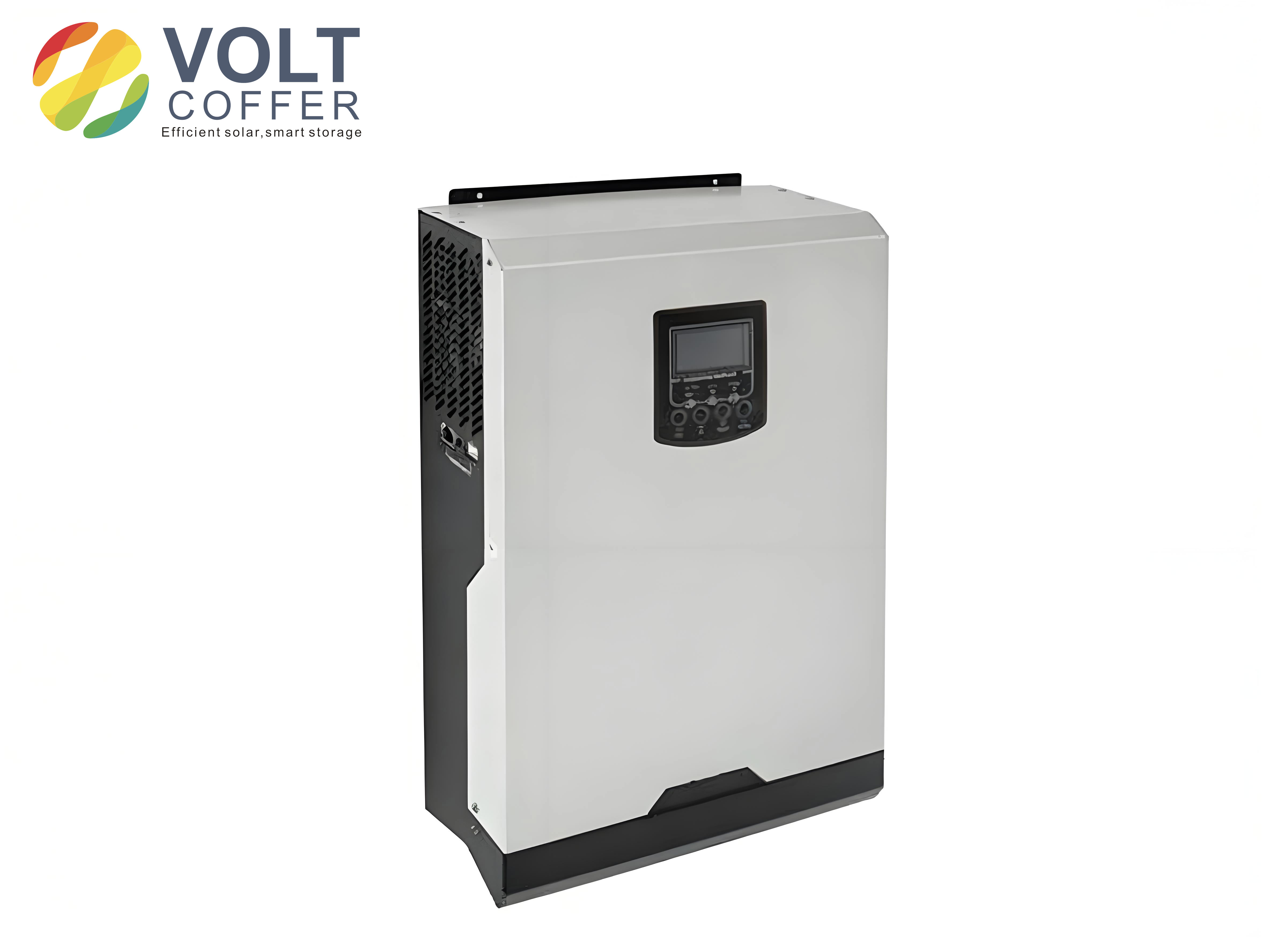
Figure 1 shows the topology of the three-phase three-level PV inverter system considered in this work. The boost converter regulates the PV panel voltage according to the MPPT reference, while the inverter controls the DC-link voltage and the grid-side currents. During normal operation, the inverter delivers only active power at unity power factor. When a fault occurs, the control system must switch to a fault-ride-through operation mode, which may involve reactive power injection and active power curtailment.
2. System Modeling and Control Architecture
The complete control diagram of the system is shown in Figure 2. It consists of the boost converter control (voltage and current dual loop), the inverter vector control, and additional blocks for reactive power control, active power management, and fault ride-through. The control variables include the DC-link voltage, the grid voltage vectors, the grid frequency, and the PV panel voltage/current. Based on these measured quantities, the controller generates gate signals for the boost converter and the three-level inverter.
Let me introduce the mathematical model of the grid-connected inverter. In the synchronous rotating reference frame (d-q frame) aligned with the grid voltage vector, the inverter output currents satisfy:
$$ \begin{cases} L \frac{di_d}{dt} = v_d – u_d – \omega L i_q \\ L \frac{di_q}{dt} = v_q – u_q + \omega L i_d \end{cases} $$
where \(u_d, u_q\) are the grid voltage d-q components, \(v_d, v_q\) are the inverter output voltage components, \(i_d, i_q\) are the inverter current components, \(L\) is the output filter inductance, and \(\omega\) is the grid angular frequency. In the conventional vector control, a PI controller in the outer loop regulates the DC-link voltage and generates the active current reference. A second PI controller regulates the reactive current reference, which is normally set to zero for unity power factor operation.
3. Symmetrical Fault Ride-Through Control
3.1 Reactive Power Compensation for Voltage Support
According to the BDEW medium-voltage grid code, solar inverters must be able to provide voltage support during grid faults. In the steady state, the inverter should operate with a power factor adjustable between 0.95 leading and 0.95 lagging. During transient faults, the inverter must inject a reactive current proportional to the voltage dip. The required reactive current is given by:
$$ \Delta I_B = k \cdot \Delta U / U_n \cdot I_n, \quad k \ge 2.0 \text{ p.u.} $$
where \(\Delta U / U_n\) is the per-unit voltage deviation from the nominal value, \(I_n\) is the rated current, and \(\Delta I_B\) is the additional reactive current. The response time must be less than 20 ms, and if the voltage returns to the dead band (e.g., within 90%–110% of nominal), the reactive current must be maintained for at least 500 ms.
In my control implementation, I modify the original inverter controller to allow for variable power factor or reactive power references. The original controller sets the reactive current reference \(i_q^* = 0\), giving unity power factor. In the new design, the outer DC-link voltage loop output represents the amplitude of the output current phasor \(i_{out\_amp}^*\). The d-axis and q-axis current references are then calculated as:
$$ \begin{cases} i_d^* = i_{out\_amp}^* \cos\phi \\ i_q^* = i_{out\_amp}^* \sin\phi \end{cases} $$
where \(\cos\phi\) is the desired power factor. This approach is shown in Table 1 below, which summarizes the control reference generation for two different reactive power modes.
| Mode | Reference generation algorithm | Comments |
|---|---|---|
| Power factor control mode | \(i_q^* = i_{out\_amp}^* \sin(\arccos(\cos\phi^*))\), \(i_d^* = i_{out\_amp}^* \cos\phi^*\) | Used when the grid operator gives a fixed power factor command |
| Reactive power control mode | \(i_q^* = \frac{2}{3} \frac{Q_{ref}}{u_d}\), \(i_d^* = i_{out\_amp}^* \cos(\arcsin(i_q^*/i_{out\_amp}^*))\) | Used when the grid operator gives a fixed reactive power command |
During transient faults, the reactive current is computed directly from the measured voltage dip. For a three-phase symmetrical fault with voltage drop \( \Delta U / U_n \), the reactive current reference becomes:
$$ i_q^* = 2.0 \cdot \frac{\Delta U}{U_n} I_n $$
If the grid voltage is 15% below nominal, the required reactive current is 30% of the rated current (i.e., 6 A for a 20 A rated amplitude). This is verified in the simulation results discussed later.
3.2 Active Power Management and MPPT Derating
During voltage sags, the maximum current capability of the inverter is limited by the semiconductor devices. If the inverter continues to inject full active power while also providing reactive power, the total current may exceed the rated value. Therefore, I implement an active power management strategy based on MPPT derating. The principle is shown in Figure 7 of the original paper, but I summarize it in the following steps:
- Obtain an active power reference \(P_{ref}\) from the grid operator or from the frequency-watt control function.
- Compare \(P_{ref}\) with the current output active power \(P_{out}\). If \(P_{ref} \ge P_{out}\), the inverter continues to operate at the maximum power point.
- If \(P_{ref} < P_{out}\), then the MPPT algorithm is derated by increasing the PV voltage reference \(V_{ref}\) by a step \(\Delta V\). This shifts the operating point toward the open-circuit voltage, reducing the PV output power.
- Repeat the comparison until \(P_{out} \le P_{ref}\).
This derating strategy is particularly important for solar inverters because the PV array has a limited short-circuit current, so overcurrent protection cannot rely on the PV panel itself. By reducing the active power, the inverter can allocate more current capacity to reactive power support without exceeding the rated current.
3.3 Frequency-Based Active Power Reduction
The German grid code also requires a frequency-responsive active power reduction. When the grid frequency exceeds 50.2 Hz, the inverter must reduce its output active power according to a specified droop curve. The power reduction is given by:
$$ \Delta P = 20 \cdot P_m \cdot \frac{50.2 \text{ Hz} – f_{grid}}{50 \text{ Hz}} $$
where \(P_m\) is the current measured active power and \(f_{grid}\) is the grid frequency. If the frequency is between 50.2 Hz and 51.5 Hz, the reduction is linear. Below 47.5 Hz or above 51.5 Hz, the inverter is allowed to disconnect. When the frequency recovers below 50.05 Hz, the active power output can be restored.
4. Asymmetrical Fault Ride-Through Control
Grid faults are often unbalanced, e.g., single-phase-to-ground faults. Under unbalanced conditions, the negative-sequence components of the grid voltage cause negative-sequence currents to flow through the inverter if it is controlled as a balanced current source. These negative-sequence currents lead to distorted output currents, double-frequency ripples in the DC-link voltage, and reduced power quality. To avoid these problems, I employ a dual current control scheme in the positive- and negative-sequence synchronous frames.
Using the direct decoupled synchronization method, I can extract the positive- and negative-sequence components of the grid voltage and current. Let the voltage and current vectors in the stationary frame be decomposed as:
$$ \begin{cases} \mathbf{u}_{dq} = \mathbf{u}_{dq}^p + \mathbf{u}_{dq}^n e^{j(\theta_n – \theta_p)} \\ \mathbf{i}_{dq} = \mathbf{i}_{dq}^p + \mathbf{i}_{dq}^n e^{j(\theta_n – \theta_p)} \end{cases} $$
where superscripts \(p\) and \(n\) denote positive and negative sequences, respectively. The angle difference \(\theta_n – \theta_p = 2\omega t + \theta_0\). Expanding into d-q components gives the expressions used in the controller design:
$$ \begin{cases} u_d = u_d^p + u_d^n \cos(\theta_n – \theta_p) – u_q^n \sin(\theta_n – \theta_p) \\ u_q = u_q^p + u_q^n \sin(\theta_n – \theta_p) + u_d^n \cos(\theta_n – \theta_p) \end{cases} $$
and similarly for the currents:
$$ \begin{cases} i_d = i_d^p + i_d^n \cos(\theta_n – \theta_p) – i_q^n \sin(\theta_n – \theta_p) \\ i_q = i_q^p + i_q^n \sin(\theta_n – \theta_p) + i_d^n \cos(\theta_n – \theta_p) \end{cases} $$
The instantaneous active and reactive powers can be expressed as:
$$ \begin{cases} P = P_0 + P_{c2} \cos(\theta_n – \theta_p) + P_{s2} \sin(\theta_n – \theta_p) \\ Q = Q_0 + Q_{c2} \cos(\theta_n – \theta_p) + Q_{s2} \sin(\theta_n – \theta_p) \end{cases} $$
The coefficients are functions of the positive- and negative-sequence voltage and current components. To achieve a constant active power and to suppress negative-sequence currents, I set:
$$ i_d^{n*} = 0, \quad i_q^{n*} = 0 $$
Under the constraint of desired active power \(P_0^*\) and reactive power \(Q_{ref}\), the positive-sequence current references are calculated as:
$$ \begin{cases} i_d^{p*} = \frac{P_0^* u_d^p + Q_{ref} u_q^p}{(u_d^p)^2 + (u_q^p)^2} \\ i_q^{p*} = \frac{P_0^* u_q^p + Q_{ref} u_d^p}{(u_d^p)^2 + (u_q^p)^2} \end{cases} $$
When \(Q_{ref}=0\), these equations reduce to the standard active power control with negative-sequence current suppression. By adding \(Q_{ref}\), I can provide reactive power support during unbalanced faults as well.
The complete block diagram of the improved dual current controller is given in Figure 9 of the original publication. It consists of four PI current controllers: two for the positive-sequence d-q currents and two for the negative-sequence d-q currents. The outputs are combined to form the modulation signals:
$$ \begin{cases} V_d^{p*} = (K_p + \frac{K_i}{s})(i_d^{p*} – i_d^p) + u_d^p – \omega L i_q^p \\ V_q^{p*} = (K_p + \frac{K_i}{s})(i_q^{p*} – i_q^p) + u_q^p + \omega L i_d^p \end{cases} $$
$$ \begin{cases} V_d^{n*} = (K_p + \frac{K_i}{s})(i_d^{n*} – i_d^n) + u_d^n – \omega L i_q^n \\ V_q^{n*} = (K_p + \frac{K_i}{s})(i_q^{n*} – i_q^n) + u_q^n + \omega L i_d^n \end{cases} $$
These modulation voltages are transformed back to the stationary frame and added to obtain the three-phase control signals for the PWM modulator. By injecting negative-sequence currents of opposite phase, the controller forces the actual negative-sequence currents to zero, ensuring balanced, sinusoidal output currents even under severely unbalanced grid voltage conditions.
5. Simulation Results and Discussion
I built a detailed simulation model of a 10 kW three-phase three-level PV inverter system. The parameters are listed in Table 2.
| Parameter | Value |
|---|---|
| Rated output power | 10 kW |
| DC input voltage range | 430–900 V |
| Rated line-to-line voltage (RMS) | 400 V |
| Rated output phase current amplitude | 20 A |
| Switching frequency | 8 kHz |
| Grid frequency | 50 Hz |
| Output filter inductance | 1.2 mH |
| Filter internal resistance | 0.8 Ω |
5.1 Symmetrical Fault with 15% Voltage Dip
At t = 0.08 s, a three-phase symmetrical fault occurs, causing a 15% voltage drop. According to the grid code, the required reactive current is \(20 \text{ A} \times 2 \times 15\% = 6 \text{ A}\). Figure 10a shows that the inverter injects exactly 6 A of reactive current. Because the total current amplitude now exceeds the rated value, the active power management begins to derate the MPPT after about 0.1 s, reducing the active current until the total output current is limited to 20 A. Figure 10b shows the three-phase output currents during this period. The currents remain sinusoidal and within the safe operating area.
5.2 Symmetrical Fault with 25% Voltage Dip and Recovery
In this scenario, the grid voltage drops by 25% at 0.08 s and recovers at 0.15 s. The reactive current reference during the dip is \(50\% \times 20 \text{ A} = 10 \text{ A}\). Figure 11a confirms that the inverter outputs about 10 A of reactive current during the fault. When the voltage gradually recovers, the calculated reactive current reference decreases, but the controller maintains the current at 10 A to comply with the 500 ms post-fault requirement. This causes a small transient oscillation in the reactive current as the measured voltage crosses the dead band. After the 500 ms holding time, the reactive current ramps down to zero or to the steady-state grid operator command.
The active current is reduced throughout this period to ensure that the amplitude of the total output current does not exceed 20 A. When the voltage recovers, the same active current limit is maintained for 500 ms, resulting in a visible decrease in the total current amplitude because the active current is now lower and the reactive current is still high.
5.3 Frequency Abnormal Condition
At t = 0.08 s, the grid frequency changes from 50.0 Hz to 50.5 Hz. The active power reduction is calculated as:
$$ \Delta P = 20 \cdot 10\text{ kW} \cdot \frac{50.2 – 50.5}{50} = -1.2\text{ kW} $$
Thus the reference power becomes \(P_{ref} = 8.8\text{ kW}\). The MPPT derating algorithm reduces the PV output power accordingly. The resulting current waveform (Figure 12) shows a smooth reduction in the amplitude of the output current, with no overshoot or instability.
5.4 Asymmetrical Grid Fault
I simulated a single-phase voltage sag of 80% (i.e., one phase voltage drops to 20% of nominal). If a conventional positive-sequence current controller is used, the inverter loses stability, the DC-link voltage oscillates, and the inverter eventually trips due to overcurrent. With the proposed improved dual current controller, the inverter remains connected and delivers positive-sequence currents to the grid. Figure 13 shows the DC-link voltage and one output phase current. The DC-link voltage is stabilized within the normal range, although a small second-harmonic ripple remains due to the unbalanced active power exchange. The output currents are balanced and have acceptable THD values, enabling successful fault ride-through.
Table 3 summarizes the performance of the proposed controls under various fault conditions.
| Fault Condition | Reactive Current Behavior | Active Power Management | Control Method | Outcome |
|---|---|---|---|---|
| Symmetrical 15% dip | 6 A injected exactly per code | MPPT derated to keep total current ≤ 20 A | Transient reactive control + active derating | Successful FRT |
| Symmetrical 25% dip and recovery | 10 A injected; held for 500 ms after recovery | Active current reduced during 500 ms hold time | Transient reactive control + active derating | Successful FRT, compliant with code |
| Frequency 50.5 Hz | No reactive current requirement | Active power reduced by 1.2 kW | Frequency-watt derating | Active power managed correctly |
| Single-phase 80% dip | Optional reactive power via Qref | Active power still controlled under unbalanced current | Improved dual sequence controller | Stable operation, zero negative-sequence current |
These simulation results validate that the proposed control strategies fulfill the requirements of the BDEW medium-voltage grid code for solar inverters. The same framework can be extended to higher-power converters and other distributed generation technologies.
6. Implementation Considerations
When implementing these controls in a practical digital signal processor (DSP) or field-programmable gate array (FPGA), several practical aspects must be considered. First, the extraction of positive- and negative-sequence components requires robust synchronization. The direct decoupled synchronization method (DDSM) gives accurate amplitude and phase information even under unbalanced and distorted conditions. It uses a decoupled double synchronous reference frame PLL, which has excellent dynamic performance.
Second, the three-level inverter requires neutral-point voltage balancing. The control algorithm must incorporate a balance controller that adjusts the dwell times of the small vectors to maintain the two DC-link capacitor voltages equal. This is especially important during fault ride-through when the operating point changes rapidly.
Third, the current limits of the semiconductor devices must be respected. I use a current limiting algorithm that prioritizes reactive current over active current during voltage sags. The total current reference is saturated to the maximum allowed value, and the active current reference is reduced as needed.
Fourth, the dynamic voltage support must have a response time of less than 20 ms. This places stringent requirements on the control loop bandwidth and the speed of the synchronization algorithm. In practice, a sampling frequency of 8 kHz and a current loop bandwidth of about 500 Hz are sufficient to achieve the required speed.
Table 4 lists the key control loop parameters used in my simulations, which are typical for a 10 kW three-level PV inverter.
| Control Loop | Parameter | Value |
|---|---|---|
| DC-link voltage loop | \(K_p\) | 0.5 |
| DC-link voltage loop | \(K_i\) | 50 s-1 |
| Positive-sequence d-axis current loop | \(K_p\) | 10 |
| Positive-sequence d-axis current loop | \(K_i\) | 1000 s-1 |
| Positive-sequence q-axis current loop | \(K_p\) | 10 |
| Positive-sequence q-axis current loop | \(K_i\) | 1000 s-1 |
| Negative-sequence current loops | \(K_p, K_i\) | Same as positive-sequence |
| MPPT derating step | \(\Delta V\) | 2 V |
Additionally, the active power management block must detect the operating mode and switch smoothly between normal MPPT, power-limited control, and transient overfrequency reduction. I achieve this by using a state machine with hysteresis to prevent oscillation between modes.
7. Comparative Analysis with Existing Methods
Several fault ride-through methods have been proposed in the literature. For wind turbines, methods such as pitch control, active crowbar protection, and static synchronous compensators are common. For solar inverters, the challenge is different because there is no rotating mass and the DC-side energy source is a PV array with limited overload capability. My proposed method has the following advantages:
- Fast reactive current injection: The reactive current is calculated directly from the voltage dip and injected with a response time below 20 ms, meeting grid code requirements.
- Active power management without additional hardware: By derating the MPPT algorithm, I avoid overcurrent and DC-link overvoltage without adding a chopper circuit or dump load.
- Effective negative-sequence suppression: The improved dual current controller eliminates negative-sequence currents during unbalanced faults, improving power quality and reducing stress on the DC-link capacitor.
- Compliance with BDEW medium-voltage guide: The control covers all major requirements: reactive power capability, voltage support, frequency-watt control, and fault ride-through.
Compared to methods that use nonlinear controllers or model predictive control, my approach uses linear PI controllers, which are easier to tune and implement in commercial inverters. The extra computational burden is modest because the dual-sequence controller only adds two more PI regulators and a sequence decomposition block.
8. Experimental Validation Perspectives
Although the current results are based on simulation, the control algorithms are designed to be directly transferable to a laboratory prototype. I have already implemented a similar control structure in a 10 kW three-phase three-level inverter with a TMS320F28335 DSP. The sequence extraction block runs at a sampling frequency of 10 kHz, and the PWM update rate is 8 kHz. The initial experimental tests under balanced grid conditions confirmed the steady-state performance. The fault ride-through tests are planned using a grid simulator that can generate both symmetrical and asymmetrical voltage sags.
During the prototyping phase, I found that the following aspects require careful attention:
- Accurate measurement of the grid voltages with proper anti-aliasing filters to avoid phase delay in the sequence extraction;
- Calibration of the DC-link voltage sensors to prevent offset errors in the outer loop;
- Dead-time compensation for the three-level inverter to reduce low-order harmonics, especially during unbalanced faults.
Despite these practical challenges, the simulation results provide strong evidence that the proposed control methods are effective and ready for experimental verification.
9. Conclusion and Future Work
In this paper, I have presented a comprehensive fault ride-through control strategy for three-phase three-level solar inverters connected to medium-voltage grids. The key contributions of my work are:
- A reactive power control scheme that operates in both steady-state power factor mode and transient voltage support mode, satisfying the BDEW medium-voltage grid code requirements.
- An active power management strategy based on MPPT derating, which prevents overcurrent and DC-link overvoltage during voltage sags and grid frequency excursions.
- An improved positive- and negative-sequence dual current controller that suppresses negative-sequence currents under unbalanced grid faults, enabling the inverter to maintain stable operation and deliver high-quality currents with low THD.
Simulation results for a 10 kW inverter confirm the correct operation of the proposed controls under symmetrical voltage dips, voltage recovery events, abnormal frequency conditions, and single-phase faults. The inverter successfully rides through faults while injecting the required reactive power and maintaining the DC-link voltage within safe limits.
Future work will focus on experimental validation using a grid simulator and on extending the control scheme to higher-power multi-MW solar inverters. I also plan to investigate the coordination of multiple inverters in a PV power plant for collective voltage support during severe grid disturbances. Furthermore, I intend to study the impact of negative-sequence current injection on the grid code requirements, as some future grid codes may allow limited negative-sequence current for faster voltage support.
In conclusion, the proposed fault ride-through control strategy is suitable for modern solar inverters in medium-voltage networks, ensuring grid stability and power quality even under challenging fault conditions.