
In this work, I design and evaluate a control strategy for a solar inverter that must remain connected and operate effectively when the three-phase grid is unbalanced. The increasing penetration of solar inverter systems in low-voltage distribution networks makes this problem important because distribution lines, single-phase loads, and unequal phase loading often produce voltage unbalance. Under such conditions, a conventional solar inverter may inject distorted and asymmetric currents, may experience power oscillations, and may even trip or degrade power quality. I therefore focus on two core elements: a robust phase-locked loop for positive-sequence voltage detection and a current-control strategy that can satisfy different power-quality objectives. I also build a simulation model to verify the design. The proposed method is intended to improve the operational resilience of the solar inverter without requiring excessive computational complexity.
The main contributions of my design can be summarized as follows. First, I use a second-order generalized integrator to extract the positive-sequence voltage and lock the grid phase under unbalanced conditions. Second, I derive current references from instantaneous power theory so that the solar inverter can suppress active-power ripple, suppress reactive-power ripple, or suppress negative-sequence current depending on the selected control target. Third, I implement a dual synchronous reference frame controller for positive- and negative-sequence components and test it in an electromagnetic transient simulation environment. The results show that the solar inverter maintains balanced currents and low harmonic distortion during an unbalanced voltage event.
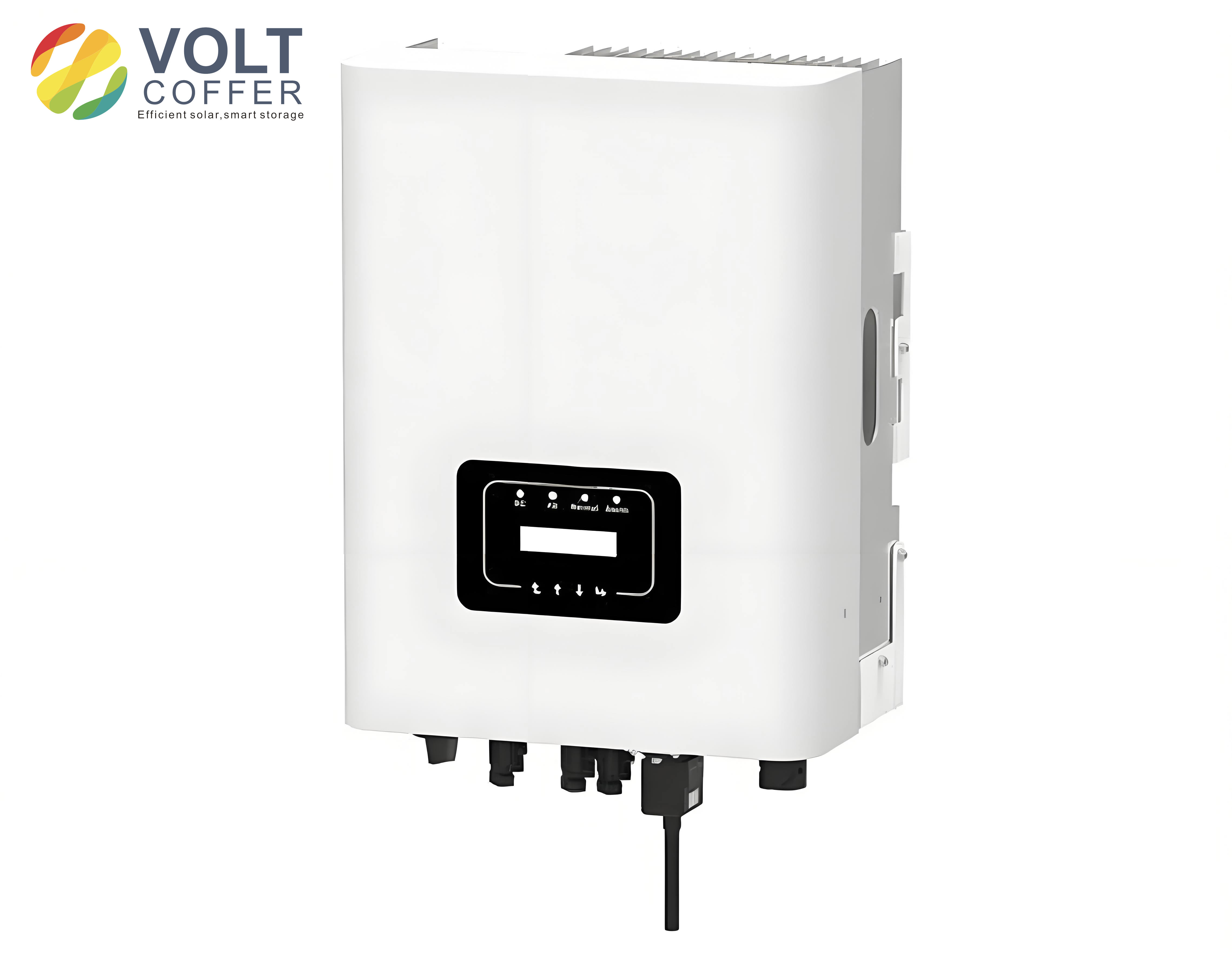
1. Problem Context and Notation
In a low-voltage network, unbalanced voltage can be caused by unequal distribution of single-phase loads, asymmetric feeder impedances, and the presence of large single-phase solar inverter units or other power electronic converters. When a solar inverter is connected to such a grid, the point of common coupling may contain positive-, negative-, and zero-sequence components. For a three-wire system without a neutral conductor, the zero-sequence component can be neglected for current control, but the negative-sequence component still has a significant impact. The solar inverter must therefore separate the positive-sequence voltage for synchronization and must control both positive- and negative-sequence currents to meet grid-code requirements.
I use the following notation throughout this article. The three-phase grid voltage is represented as a vector of phase voltages. The positive and negative sequence components are extracted using symmetrical component theory. The solar inverter is assumed to be a three-phase voltage-source converter with an LCL filter and a DC link. The control system operates in the synchronous reference frame, with separate positive- and negative-sequence dq frames. The main symbols are listed in Table 1.
| Symbol | Meaning |
|---|---|
| $$ v_{abc} $$ | Three-phase grid voltage vector |
| $$ v_{abc}^{+} $$ | Positive-sequence voltage component |
| $$ v_{abc}^{-} $$ | Negative-sequence voltage component |
| $$ v_{abc}^{0} $$ | Zero-sequence voltage component |
| $$ v_{\alpha\beta} $$ | Voltage vector in stationary alpha-beta frame |
| $$ v_{d}^{+}, v_{q}^{+} $$ | Positive-sequence dq voltage components |
| $$ v_{d}^{-}, v_{q}^{-} $$ | Negative-sequence dq voltage components |
| $$ i_{d}^{+}, i_{q}^{+} $$ | Positive-sequence dq current components |
| $$ i_{d}^{-}, i_{q}^{-} $$ | Negative-sequence dq current components |
| $$ \omega $$ | Grid angular frequency |
| $$ \omega’ $$ | Estimated angular frequency from the PLL |
| $$ \theta $$ | Estimated grid phase angle |
| $$ p_0, q_0 $$ | Average active and reactive power |
| $$ p_{c2}, p_{s2} $$ | Active-power ripple coefficients |
| $$ q_{c2}, q_{s2} $$ | Reactive-power ripple coefficients |
2. Sequence Decomposition and SOGI-Based Phase Locking
When the grid is unbalanced, the three-phase voltage can be decomposed into positive-, negative-, and zero-sequence components. I write this decomposition as
$$ v_{abc} = v_{abc}^{+} + v_{abc}^{-} + v_{abc}^{0} $$
For a three-wire system, the zero-sequence component is not present in the line currents and can be omitted from the current-control design. The positive-sequence component is obtained by
$$ v_{abc}^{+} = T^{+} v_{abc} = \frac{1}{3} \begin{bmatrix} 1 & a & a^2 \\ a^2 & 1 & a \\ a & a^2 & 1 \end{bmatrix} \begin{bmatrix} v_a \\ v_b \\ v_c \end{bmatrix} $$
where the complex operator is defined as
$$ a = e^{j2\pi/3} $$
The negative-sequence component is obtained by
$$ v_{abc}^{-} = T^{-} v_{abc} = \frac{1}{3} \begin{bmatrix} 1 & a^2 & a \\ a & 1 & a^2 \\ a^2 & a & 1 \end{bmatrix} \begin{bmatrix} v_a \\ v_b \\ v_c \end{bmatrix} $$
After applying the Clarke transformation, the alpha-beta voltage components are obtained. The Clarke transformation matrix I use is
$$ T_{\alpha\beta} = \frac{2}{3} \begin{bmatrix} 1 & -\frac{1}{2} & -\frac{1}{2} \\ 0 & \frac{\sqrt{3}}{2} & -\frac{\sqrt{3}}{2} \end{bmatrix} $$
The positive- and negative-sequence alpha-beta components are then
$$ v_{\alpha\beta}^{+} = T_{\alpha\beta} v_{abc}^{+} $$
$$ v_{\alpha\beta}^{-} = T_{\alpha\beta} v_{abc}^{-} $$
For real-time implementation, I need a method to separate the positive and negative sequences without a long delay. I use the second-order generalized integrator, which generates an orthogonal signal from a single-phase input. The sequence separation can be expressed as
$$ v_{\alpha\beta}^{+} = \frac{1}{2} \begin{bmatrix} 1 & -q \\ q & 1 \end{bmatrix} v_{\alpha\beta} $$
$$ v_{\alpha\beta}^{-} = \frac{1}{2} \begin{bmatrix} 1 & q \\ -q & 1 \end{bmatrix} v_{\alpha\beta} $$
where $$ q $$ is a 90-degree phase-lag operator. The SOGI produces the orthogonal signal and filters harmonics at the same time. The transfer functions of the SOGI are
$$ D(s) = \frac{v’}{v} = \frac{k \omega’ s}{s^2 + k \omega’ s + \omega’^2} $$
$$ Q(s) = \frac{q v’}{v} = \frac{k \omega’^2}{s^2 + k \omega’ s + \omega’^2} $$
In these expressions, $$ v $$ is the input sinusoidal signal, $$ v’ $$ is the in-phase output, $$ qv’ $$ is the quadrature output, $$ \omega’ $$ is the estimated center frequency, and $$ k $$ is the damping coefficient. I select $$ k = \sqrt{2} $$ to obtain a good compromise between filtering capability and dynamic response. When the center frequency of the SOGI matches the input frequency, the output $$ v’ $$ has the same amplitude and phase as the input, while $$ qv’ $$ has the same amplitude but is phase-shifted by 90 degrees. This property is essential for the solar inverter phase-locking loop.
I compare the SOGI-based method with other phase-locking approaches. The comparison is summarized in Table 2.
| Method | Main Advantage | Main Limitation |
|---|---|---|
| Quarter-cycle delay method | Simple implementation based on symmetrical components | Delay limits dynamic speed; poor under frequency variation |
| Decoupled double synchronous reference frame PLL | High steady-state accuracy | Depends on phase feedback; large overshoot and long recovery under phase jump |
| Low-pass filter before PLL | Reduces harmonics | Introduces phase offset and slows response |
| Adaptive observer PLL | Good disturbance rejection | High computational burden and complex tuning |
| SOGI-based PLL | Fast orthogonal signal generation, good filtering, simple structure | Requires careful tuning of gain and center frequency |
The SOGI-based PLL I design uses the positive-sequence q-axis voltage as the error signal. In the synchronous reference frame, the positive-sequence q-axis voltage becomes zero when the estimated phase angle is aligned with the grid voltage vector. Therefore, a proportional-integral controller can drive this error to zero. The estimated angular frequency is
$$ \omega’ = \omega_0 + K_p \epsilon + K_i \int \epsilon \, dt $$
where $$ \omega_0 $$ is the nominal grid angular frequency and $$ \epsilon $$ is the phase error. The estimated phase angle is then obtained by integration:
$$ \theta = \int \omega’ \, dt $$
I choose the PI gains to achieve a settling time of approximately one fundamental cycle while maintaining stability under frequency deviations. The SOGI center frequency is updated by $$ \omega’ $$, which gives the PLL frequency-adaptive capability. This is important for a solar inverter because grid frequency may vary slightly around its nominal value, and a fixed-frequency PLL may lose accuracy.
3. Unbalanced Control Strategy Based on Instantaneous Power
Once the positive-sequence phase angle is known, I control the solar inverter in the positive- and negative-sequence synchronous reference frames. Under unbalanced grid voltage, the instantaneous active and reactive powers contain oscillating terms at twice the grid frequency. Using instantaneous power theory, I express the active power as
$$ P(t) = p_0 + p_{c2} \cos(2\omega t) + p_{s2} \sin(2\omega t) $$
and the reactive power as
$$ Q(t) = q_0 + q_{c2} \cos(2\omega t) + q_{s2} \sin(2\omega t) $$
The average active power $$ p_0 $$ and average reactive power $$ q_0 $$ are the DC terms, while $$ p_{c2} $$, $$ p_{s2} $$, $$ q_{c2} $$, and $$ q_{s2} $$ are the ripple coefficients. These quantities are related to the positive- and negative-sequence currents by a matrix equation. I write the power vector as
$$ \begin{bmatrix} p_0 \\ p_{c2} \\ p_{s2} \\ q_0 \\ q_{c2} \\ q_{s2} \end{bmatrix} = M \begin{bmatrix} i_d^{+} \\ i_q^{+} \\ i_d^{-} \\ i_q^{-} \end{bmatrix} $$
For a three-phase system, the matrix $$ M $$ is
$$ M = \frac{3}{2} \begin{bmatrix} v_d^+ & v_q^+ & v_d^- & v_q^- \\ v_d^- & v_q^- & v_d^+ & v_q^+ \\ v_q^- & -v_d^- & -v_q^+ & v_d^+ \\ v_q^+ & -v_d^+ & v_q^- & -v_d^- \\ v_q^- & -v_d^- & v_q^+ & -v_d^+ \\ -v_d^- & -v_q^- & v_d^+ & v_q^+ \end{bmatrix} $$
Because there are six power variables and only four current variables, I cannot independently control all six power terms at the same time. I must choose a control target and set the remaining oscillating terms to zero or allow them to vary. This is the central idea of the unbalanced control strategy for the solar inverter. I consider three typical targets:
1. Suppress negative-sequence current.
2. Suppress active-power ripple.
3. Suppress reactive-power ripple.
For each target, I solve for the current references by selecting the appropriate rows of the power matrix. The control targets and their constraints are summarized in Table 3.
| Control Target | Constraints | Main Benefit |
|---|---|---|
| Suppress negative-sequence current | $$ i_d^{-*} = 0 $$, $$ i_q^{-*} = 0 $$ | Balanced three-phase currents, reduced current unbalance |
| Suppress active-power ripple | $$ p_{c2} = 0 $$, $$ p_{s2} = 0 $$ | Smoother DC-link power, reduced double-frequency stress |
| Suppress reactive-power ripple | $$ q_{c2} = 0 $$, $$ q_{s2} = 0 $$ | Improved reactive power quality |
When the target is to suppress negative-sequence current, I set the negative-sequence current references to zero. The remaining power equations for average active and reactive power are
$$ p_0 = \frac{3}{2} \left( v_d^+ i_d^+ + v_q^+ i_q^+ \right) $$
$$ q_0 = \frac{3}{2} \left( v_q^+ i_d^+ – v_d^+ i_q^+ \right) $$
Solving for the positive-sequence current references gives
$$ i_d^{+*} = \frac{2}{3} \frac{v_d^+ p_0^* + v_q^+ q_0^*}{(v_d^+)^2 + (v_q^+)^2} $$
$$ i_q^{+*} = \frac{2}{3} \frac{v_q^+ p_0^* – v_d^+ q_0^*}{(v_d^+)^2 + (v_q^+)^2} $$
This target is very useful for the solar inverter because it prevents the injection of negative-sequence current into the grid, which helps satisfy power-quality requirements and avoids excessive current unbalance.
When the target is to suppress active-power ripple, I set $$ p_{c2} = 0 $$ and $$ p_{s2} = 0 $$. The current references are obtained from the four equations corresponding to $$ p_0 $$, $$ p_{c2} $$, $$ p_{s2} $$, and $$ q_0 $$. The resulting linear system is
$$ \begin{bmatrix} v_d^+ & v_q^+ & v_d^- & v_q^- \\ v_d^- & v_q^- & v_d^+ & v_q^+ \\ v_q^- & -v_d^- & -v_q^+ & v_d^+ \\ v_q^+ & -v_d^+ & v_q^- & -v_d^- \end{bmatrix} \begin{bmatrix} i_d^+ \\ i_q^+ \\ i_d^- \\ i_q^- \end{bmatrix} = \frac{2}{3} \begin{bmatrix} p_0^* \\ 0 \\ 0 \\ q_0^* \end{bmatrix} $$
Solving this system yields the current references that eliminate the active-power ripple. This target is attractive when the DC-link capacitor is small or when the solar inverter must reduce double-frequency stress on the DC link.
When the target is to suppress reactive-power ripple, I set $$ q_{c2} = 0 $$ and $$ q_{s2} = 0 $$. The corresponding linear system uses the rows for $$ p_0 $$, $$ q_0 $$, $$ q_{c2} $$, and $$ q_{s2} $$:
$$ \begin{bmatrix} v_d^+ & v_q^+ & v_d^- & v_q^- \\ v_q^+ & -v_d^+ & v_q^- & -v_d^- \\ v_q^- & -v_d^- & v_q^+ & -v_d^+ \\ -v_d^- & -v_q^- & v_d^+ & v_q^+ \end{bmatrix} \begin{bmatrix} i_d^+ \\ i_q^+ \\ i_d^- \\ i_q^- \end{bmatrix} = \frac{2}{3} \begin{bmatrix} p_0^* \\ q_0^* \\ 0 \\ 0 \end{bmatrix} $$
This target is useful when reactive power quality is the main concern. In my design, I can switch between these targets by changing the constraints and solving the corresponding reduced matrix equation. I can also use a pseudo-inverse formulation when the system is overdetermined, but for the three selected targets the reduced system is square and well-conditioned under normal voltage unbalance.
4. Dual Synchronous Reference Frame Current Control
After the current references are calculated, I implement a dual synchronous reference frame controller. The positive-sequence current is controlled in a frame rotating at $$ +\omega $$, and the negative-sequence current is controlled in a frame rotating at $$ -\omega $$. This allows independent regulation of positive- and negative-sequence currents. The control laws for the positive-sequence dq axes are
$$ v_{d}^{+*} = \left( K_{p} + \frac{K_{i}}{s} \right) (i_d^{+*} – i_d^+) – \omega L i_q^+ + v_{gd}^+ $$
$$ v_{q}^{+*} = \left( K_{p} + \frac{K_{i}}{s} \right) (i_q^{+*} – i_q^+) + \omega L i_d^+ + v_{gq}^+ $$
For the negative-sequence dq axes, the cross-coupling terms have opposite signs because the negative-sequence frame rotates in the opposite direction. The control laws are
$$ v_{d}^{-*} = \left( K_{p} + \frac{K_{i}}{s} \right) (i_d^{-*} – i_d^-) + \omega L i_q^- + v_{gd}^- $$
$$ v_{q}^{-*} = \left( K_{p} + \frac{K_{i}}{s} \right) (i_q^{-*} – i_q^-) – \omega L i_d^- + v_{gq}^- $$
These equations include feedforward of the grid voltage and decoupling of the inductive cross-coupling. The outputs are transformed back to the stationary frame and then to the three-phase modulating signals. The solar inverter uses these signals to generate the switching pulses. I also include a DC-link voltage controller that generates the active-power reference. The DC-link voltage control law is
$$ i_{dc}^* = K_{pv} (V_{dc}^* – V_{dc}) + K_{iv} \int (V_{dc}^* – V_{dc}) \, dt $$
$$ p_0^* = V_{dc} i_{dc}^* $$
The reactive-power reference $$ q_0^* $$ is set by the grid operator or by a reactive-power dispatch command. In my simulation, I set $$ q_0^* = 0 $$ to focus on active-power injection, but the design supports reactive-power control as well.
The LCL filter between the solar inverter and the grid attenuates switching harmonics. I model it with the grid-side inductance $$ L_1 $$, the inverter-side inductance $$ L_2 $$, the filter capacitance $$ C $$, and the damping resistance $$ R $$. The dynamic equations of the LCL filter are
$$ L_1 \frac{di_1}{dt} = v_i – v_c – R i_1 $$
$$ L_2 \frac{di_2}{dt} = v_c – v_g $$
$$ C \frac{dv_c}{dt} = i_1 – i_2 $$
In the control design, I treat the LCL filter as part of the plant and tune the current controller with sufficient phase margin. The resonant frequency of the LCL filter must be placed well above the current-control bandwidth and well below the switching frequency. This ensures that the solar inverter remains stable while achieving good harmonic attenuation.
5. Simulation Model and Parameters
I build a simulation model in PSCAD/EMTDC to verify the proposed control strategy. The model represents a three-level solar inverter connected to a low-voltage grid through an LCL filter. The simulation parameters are listed in Table 4.
| Parameter | Value |
|---|---|
| Grid voltage peak | 220 V |
| DC-link capacitors | $$ C_1 = C_2 = 300 \, \mu\text{F} $$ |
| Rated power | 10 kW |
| Grid-side inductance | $$ L_1 = 0.05 \, \text{mH} $$ |
| Inverter-side inductance | $$ L_2 = 0.45 \, \text{mH} $$ |
| Filter capacitance | $$ C = 10 \, \mu\text{F} $$ |
| Damping resistance | $$ R = 1 \, \Omega $$ |
| Current controller proportional gain | $$ K_p = 8 $$ |
| Current controller integral gain | $$ K_i = 10 $$ |
| Voltage controller proportional gain | $$ K_{pv} = 0.5 $$ |
| Voltage controller integral gain | $$ K_{iv} = 0.08 $$ |
The simulation scenario is designed to create a severe unbalanced voltage event. At $$ t = 0.2 \, \text{s} $$, a single-phase-to-ground fault occurs on phase A. The phase A voltage drops to 50 percent of its nominal value, while the other phases remain close to nominal. At $$ t = 0.25 \, \text{s} $$, the fault is cleared, and the voltage recovers to its normal balanced condition. I compare two cases: a conventional control strategy without negative-sequence compensation and the proposed dual-frame control strategy with negative-sequence current suppression.
6. Simulation Results and Discussion
In the conventional case, the solar inverter does not separate the negative-sequence component. As a result, the grid current becomes highly unbalanced during the fault. The phase currents have different amplitudes, and the harmonic distortion increases significantly. The total harmonic distortion of the phase A current exceeds the grid-code limit, and the solar inverter may be disconnected by protection relays. This behavior is unacceptable for a modern solar inverter that is expected to ride through short unbalanced voltage events.
In the proposed case, the SOGI-based PLL accurately tracks the positive-sequence phase angle. The dual synchronous reference frame controller regulates the positive- and negative-sequence currents independently. Because the control target is to suppress negative-sequence current, the negative-sequence current references are set to zero, and the solar inverter injects nearly balanced three-phase currents even though the grid voltage is unbalanced. The current total harmonic distortion remains around 3 percent, which is well within typical limits. After the fault is cleared, the solar inverter returns to its normal operating point quickly, with a smooth recovery and no significant overshoot.
Table 5 summarizes the performance comparison between the conventional strategy and the proposed strategy.
| Performance Index | Conventional Strategy | Proposed Strategy |
|---|---|---|
| Current symmetry during fault | Highly unbalanced | Nearly balanced |
| Phase A current THD | Exceeds grid-code limit | Approximately 3% |
| Negative-sequence current | Large | Suppressed |
| Active-power ripple | Present | Reduced depending on target |
| Recovery after fault clearing | Slow and oscillatory | Fast and smooth |
| Control complexity | Low | Moderate |
The simulation results confirm that the proposed method improves the operating performance of the solar inverter under unbalanced grid conditions. The SOGI-based PLL provides a fast and accurate phase angle even when the voltage contains negative-sequence components. The instantaneous power-based current reference calculation ensures that the solar inverter can meet different control objectives. The dual-frame current controller then tracks the references with good dynamic response. This combination is effective for a grid-connected solar inverter in a low-voltage distribution network.
7. Robustness and Sensitivity
I also examine the sensitivity of the proposed control strategy to frequency variation and voltage harmonics. Because the SOGI center frequency is updated by the PLL, the phase-locking performance remains acceptable when the grid frequency deviates from its nominal value. I test a frequency step of $$ \pm 0.5 \, \text{Hz} $$ and observe that the PLL re-locks within a few cycles. The solar inverter current remains stable, although a small transient appears in the current amplitude. This transient is much smaller than what would occur with a fixed-frequency PLL.
For voltage harmonics, the SOGI provides inherent filtering at the fundamental frequency. The orthogonal signal generation is less affected by low-order harmonics than a simple delay-based method. However, if the grid voltage contains strong fifth- or seventh-order harmonics, the extracted positive-sequence voltage may still have some ripple. I can reduce this ripple by narrowing the SOGI bandwidth or by adding a harmonic compensator. In my design, the current controller also helps reject harmonic disturbances because it has sufficient gain at the fundamental frequency and the LCL filter attenuates switching-frequency components.
Table 6 shows the sensitivity of the main performance indicators under several grid conditions.
| Condition | PLL Locking Time | Current THD | Current Unbalance |
|---|---|---|---|
| Balanced grid, nominal frequency | Very fast | Low | Very low |
| Unbalanced grid, nominal frequency | Fast | Approximately 3% | Suppressed |
| Unbalanced grid, frequency step +0.5 Hz | Within a few cycles | Approximately 3.5% | Suppressed |
| Unbalanced grid, frequency step -0.5 Hz | Within a few cycles | Approximately 3.5% | Suppressed |
| Unbalanced grid with fifth harmonic | Fast | Slightly higher | Suppressed |
The computational burden of the proposed method is moderate. The SOGI requires only two integrators and a few multiplications per phase. The sequence extraction and dual-frame current control require coordinate transformations and PI regulators, which are standard in modern solar inverter controllers. The matrix inversion for current reference calculation can be precomputed or simplified for the selected control target. Therefore, the method is suitable for practical implementation in a digital signal processor or microcontroller.
8. Design Procedure
Based on my analysis, I summarize the design procedure for the solar inverter control strategy as follows.
1. Measure the three-phase grid voltages and currents.
2. Use the SOGI to generate orthogonal voltage signals and extract the positive-sequence alpha-beta components.
3. Use the SOGI-based PLL to estimate the grid frequency and phase angle.
4. Transform the positive- and negative-sequence voltages and currents into their respective dq frames.
5. Select a control target: suppress negative-sequence current, suppress active-power ripple, or suppress reactive-power ripple.
6. Calculate the positive- and negative-sequence current references using the reduced power matrix.
7. Regulate the currents with the dual synchronous reference frame PI controllers.
8. Add feedforward and decoupling terms to improve dynamic response.
9. Transform the voltage references back to the stationary frame and generate the switching signals.
10. Verify the design with electromagnetic transient simulation and, if possible, with hardware-in-the-loop testing.
This procedure is general and can be adapted to different solar inverter topologies and power ratings. The key is to maintain accurate positive-sequence synchronization and to choose a current-reference strategy that matches the grid-code requirements and the hardware constraints.
9. Comparison of Current Reference Strategies
The choice of current reference strategy has a direct impact on the solar inverter performance. I compare the three strategies in Table 7.
| Strategy | Negative-Sequence Current | Active-Power Ripple | Reactive-Power Ripple | Typical Use Case |
|---|---|---|---|---|
| Suppress negative-sequence current | Zero | Present | Present | Grid-code compliance and balanced current injection |
| Suppress active-power ripple | Present | Zero | Present | Reduced DC-link stress and smoother power |
| Suppress reactive-power ripple | Present | Present | Zero | Reactive-power quality improvement |
For a solar inverter connected to a weak low-voltage grid, I prefer the negative-sequence current suppression strategy because it keeps the current balanced and reduces the risk of overcurrent in one phase. If the DC-link capacitor is small, the active-power ripple suppression strategy may be more suitable because it reduces the double-frequency voltage ripple on the DC link. If the grid operator requires strict reactive-power quality, the reactive-power ripple suppression strategy can be selected. In a practical solar inverter, the controller can switch between these strategies based on the operating condition and the grid-code requirement.
10. Harmonic Performance and Filter Considerations
The LCL filter is an important part of the solar inverter system. It attenuates the switching harmonics generated by the pulse-width modulation process. I design the LCL filter so that its resonant frequency is placed between the current-control bandwidth and the switching frequency. The resonant frequency is approximately
$$ f_{res} = \frac{1}{2\pi} \sqrt{\frac{L_1 + L_2}{L_1 L_2 C}} $$
With the parameters in Table 4, the resonant frequency is well above the fundamental frequency and below the switching frequency. The damping resistor $$ R $$ helps suppress the resonant peak. Without damping, the LCL filter could cause oscillations and instability. I use a passive damping resistor in series with the filter capacitor, which is simple and reliable. An active damping method could also be used, but it requires additional sensors and control complexity.
The current total harmonic distortion depends on the LCL filter, the switching frequency, and the current controller bandwidth. In my simulation, the proposed control strategy maintains the current THD around 3 percent during the unbalanced voltage event. This is a significant improvement over the conventional strategy, which produces much higher distortion. The solar inverter therefore remains compliant with typical grid-code harmonic limits.
11. DC-Link Voltage Control and Power Balance
The DC-link voltage controller regulates the active-power reference for the solar inverter. When the grid is unbalanced, the instantaneous power may contain ripple. If the control target does not suppress active-power ripple, the DC-link voltage will also contain a double-frequency ripple. The amplitude of this ripple depends on the DC-link capacitance and the power rating. I size the DC-link capacitor to keep the voltage ripple within an acceptable range. The DC-link voltage dynamics can be approximated by
$$ C_{dc} V_{dc} \frac{dV_{dc}}{dt} = P_{pv} – P_{grid} $$
where $$ C_{dc} $$ is the total DC-link capacitance, $$ P_{pv} $$ is the power from the solar array, and $$ P_{grid} $$ is the power injected into the grid. By controlling the grid current, the solar inverter can regulate the power flow and maintain the DC-link voltage. In my design, the DC-link voltage controller generates the active-power reference, which is then used in the current-reference calculation. This ensures that the solar inverter delivers the available solar power while maintaining stable DC-link voltage.
12. Practical Implementation Considerations
For a practical solar inverter, the control algorithm must be implemented in a digital signal processor with a fixed sampling frequency. The SOGI and PLL should be discretized using a suitable method, such as the Tustin transformation or the forward Euler method. The sampling frequency should be much higher than the grid frequency and the SOGI center frequency. I typically use a sampling frequency of 10 kHz or higher for a 50 Hz grid. The current control loop should be synchronized with the pulse-width modulation carrier to minimize delay. The sequence extraction and coordinate transformations should be performed at the same sampling rate as the current control loop.
The matrix inversion for current reference calculation can be simplified by selecting a specific control target. For negative-sequence current suppression, the current references can be calculated directly using the equations derived earlier. For active-power ripple suppression or reactive-power ripple suppression, the reduced matrix is 4 by 4 and can be solved analytically or numerically. Since the matrix depends on the positive- and negative-sequence voltages, it must be updated in real time. However, the computational cost is manageable for a modern digital signal processor.
Another practical consideration is the current limit of the solar inverter. Under severe voltage unbalance, the current references may exceed the rated current. I therefore include a current limiting function that scales the references proportionally when the current magnitude exceeds the limit. This prevents overcurrent and protects the semiconductor devices. The current limiting function should not distort the phase balance unnecessarily; therefore, I scale the positive- and negative-sequence references by the same factor.
13. Conclusion
I have designed a control strategy for a solar inverter operating under unbalanced grid conditions. The strategy uses a SOGI-based PLL to extract the positive-sequence voltage and estimate the grid phase angle. It then uses instantaneous power theory to calculate current references for different control targets. A dual synchronous reference frame controller regulates the positive- and negative-sequence currents independently. Simulation results show that the proposed method keeps the solar inverter currents balanced during a single-phase voltage drop, reduces total harmonic distortion to around 3 percent, and allows fast recovery after the fault is cleared.
The main advantages of my design are fast and accurate synchronization, flexible current reference selection, and good harmonic performance. The method is suitable for a grid-connected solar inverter in a low-voltage distribution network where voltage unbalance is common. In future work, I plan to investigate adaptive control targets that automatically switch based on grid conditions, and I will test the algorithm on a hardware prototype to validate its real-time performance. I will also study the interaction between multiple solar inverter units in a microgrid and examine how the proposed control strategy affects system stability.