
In this thesis, I focus on the instantaneous power control problem of a microgrid that integrates a supercapacitor–lithium battery hybrid energy storage system (energy storage system). The motivation comes from the need to suppress DC bus voltage fluctuations and grid frequency fluctuations caused by high-power load steps in shipboard or islanded microgrids. A single type of energy storage system cannot simultaneously provide high power density and high energy density. Therefore, I propose a hybrid energy storage system that combines a supercapacitor and a lithium battery to improve the dynamic performance and operational safety of the microgrid.
The research work is organized as follows. First, I analyze the topology and mathematical models of the hybrid energy storage system. Second, I design a fast power response control strategy based on incremental model predictive control (IMPC) and a power allocation scheme based on rational function fitting. Third, I propose a linear fuzzy adaptive frequency control strategy for grid-connected frequency regulation. Finally, I build a hardware-in-the-loop experimental platform and verify the proposed methods experimentally.
1. Microgrid Topology and Mathematical Modeling
The proposed microgrid consists of a turbine generator, an AC/DC converter, a DC/DC converter, a DC bus, a supercapacitor energy storage system, a lithium battery energy storage system, DC loads, and AC loads. The turbine generator is the main power source, while the hybrid energy storage system is connected to the DC bus through bidirectional DC/DC converters. The AC/DC converter connects the DC bus to the AC bus through a filter and transformer.
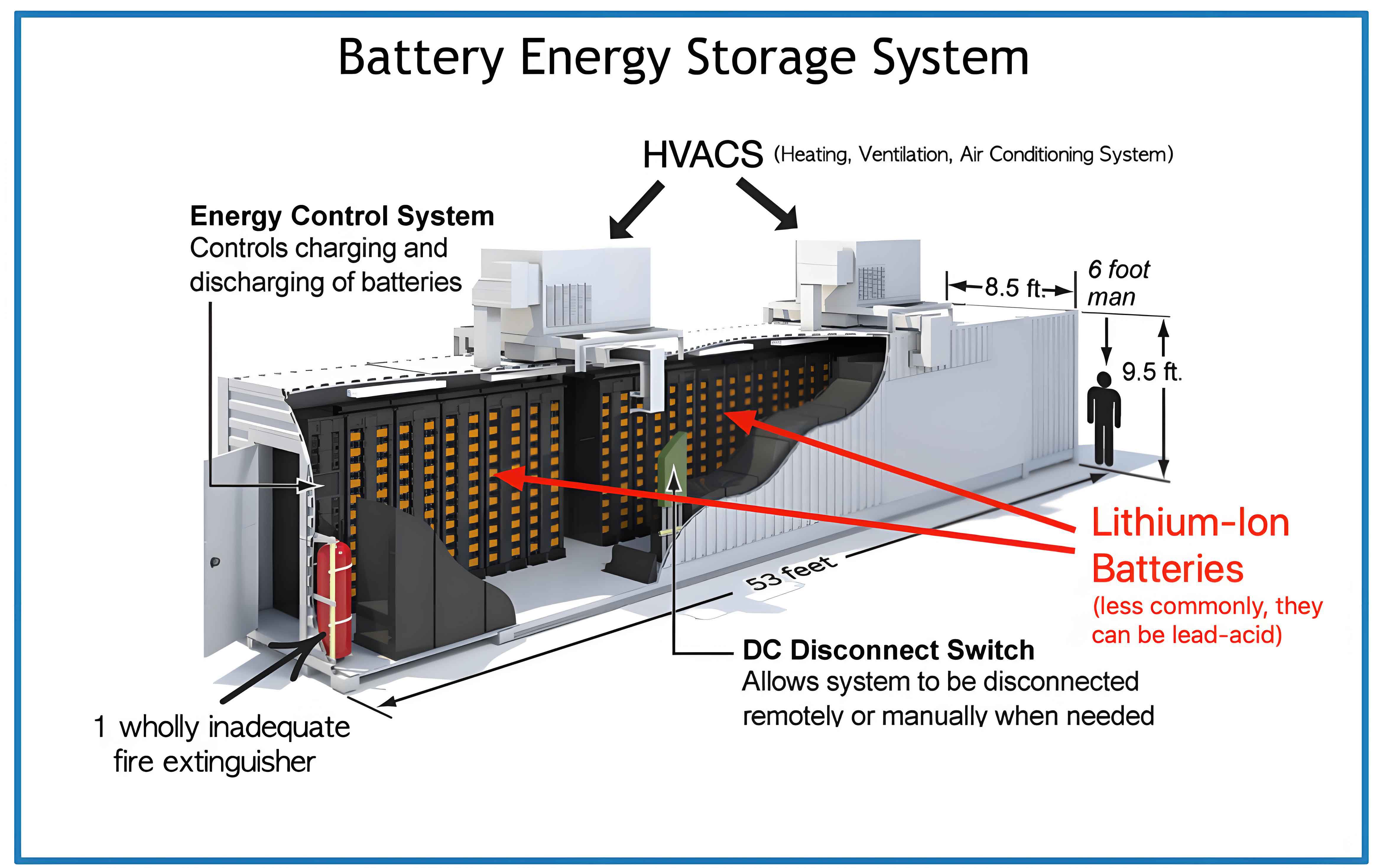
The hybrid energy storage system uses an active topology, where both the supercapacitor and the lithium battery are connected to the DC bus via individual DC/DC converters. This topology allows independent control of each energy storage system, enabling flexible power sharing and improving the utilization of both energy storage units.
1.1 Supercapacitor Model
The supercapacitor is modeled as a series RC circuit. The terminal voltage can be expressed as:
$$ U_{sc}(t) = R_{ESR} I_{sc}(t) + U_c(t) $$
where \(R_{ESR}\) is the internal resistance, \(I_{sc}\) is the current, and \(U_c\) is the capacitor voltage. The available energy of the supercapacitor is:
$$ E_{sc} = \frac{1}{2} C \left( U_{sc\max}^2 – U_{sc\min}^2 \right) $$
The state of charge (SOC) of the supercapacitor is defined as:
$$ SOC_{sc} = \frac{U_{sc}^2 – U_{sc\min}^2}{U_{sc\max}^2 – U_{sc\min}^2} $$
1.2 Lithium Battery Model
The lithium battery is modeled using the Thevenin equivalent circuit. The dynamic equations are:
$$ U_L = U_{oc} + I_t R_a + U_p $$
$$ I_t = C_p \frac{dU_p}{dt} + \frac{U_p}{R_b} $$
The SOC of the lithium battery is calculated by the ampere-hour integration method:
$$ SOC_B = SOC_{B0} – \frac{1}{C_B} \int_0^t I_t dt $$
where \(SOC_{B0}\) is the initial SOC and \(C_B\) is the nominal capacity.
1.3 Bidirectional DC/DC Converter Model
The lithium battery and the supercapacitor are each connected to the DC bus through a bidirectional DC/DC converter. For the lithium battery side, the average model over one switching cycle is:
$$ L_B \frac{di_B}{dt} = V_{in} – (1 – d_B) V_{dc} $$
Similarly, for the supercapacitor side:
$$ L_S \frac{di_S}{dt} = V_S – (1 – d_S) V_{dc} $$
The small-signal model of the DC/DC converter is derived for controller design purposes. The control-to-inductor-current transfer function is important for current loop design.
1.4 Bidirectional AC/DC Converter Model
The AC/DC converter connects the DC bus to the AC grid. Using the dq reference frame, the dynamics are:
$$ L_g \frac{di_{gd}}{dt} = -R_g i_{gd} + \omega_g L_g i_{gq} + V_{cond} – V_{gd} $$
$$ L_g \frac{di_{gq}}{dt} = -R_g i_{gq} – \omega_g L_g i_{gd} + V_{conq} – V_{gq} $$
The active and reactive power are:
$$ P = 1.5 V_{gd} i_{gd} $$
$$ Q = -1.5 V_{gd} i_{gq} $$
1.5 Turbine Generator System Model
The turbine generator consists of a speed governor, a steam turbine, and a synchronous generator. The electromechanical dynamics are described by:
$$ T_j \frac{d\omega}{dt} = P_m – P_e $$
where \(T_j\) is the inertia time constant, \(P_m\) is the mechanical power, and \(P_e\) is the electrical power. The governor is modeled as a PI controller. The frequency response of the microgrid is affected by the turbine governor dynamics and the system inertia.
2. Frequency Fluctuation Mechanism of the Microgrid
The frequency of the microgrid is directly related to the rotor speed of the synchronous generator:
$$ f = \frac{n p}{60} $$
where \(n\) is the rotor speed and \(p\) is the number of pole pairs. When a large load step occurs, the turbine generator cannot increase its output power quickly because of the large inertia and slow governor response. This causes a power imbalance:
$$ \frac{dP_g}{dt} < \frac{dP_L}{dt} $$
where \(P_g\) is the generator output power and \(P_L\) is the load power. As a result, the system frequency deviates from its nominal value. The hybrid energy storage system must compensate the unbalanced power to suppress frequency fluctuations.
The power balance equations for different scenarios are summarized below.
| Scenario | Power balance equation |
|---|---|
| Load increase | \(P_g + P_H = P_L\) |
| Load decrease | \(P_g + P_H = P_L\) |
| DC bus disturbance | \(P_H = P_{B} + P_{S}\) |
Thus, the control objectives are to minimize the frequency deviation and the DC bus voltage deviation while satisfying power and power-rate constraints of the energy storage system.
3. Fast Power Response Control of Hybrid Energy Storage System
3.1 Overall Control Structure
To suppress DC bus voltage fluctuations caused by high-power load steps, I propose a fast power response control strategy based on incremental model predictive control (IMPC). The overall control block diagram is shown below.
The control structure contains two main parts: a power predictive control and a current control based on IMPC. The power predictive control generates the reference power for the hybrid energy storage system. The power allocation strategy divides the reference power between the lithium battery and the supercapacitor. The current control loop ensures that the actual currents track the reference currents quickly.
3.2 Incremental Model Predictive Current Control
The discrete-time model of the hybrid energy storage system can be written in a unified form. For the lithium battery:
$$ i_B(k+1) = i_B(k) + \frac{T}{L_B} \left[ V_{in} – (1-d_B(k)) V_{dc} \right] $$
Define the control input \(u_B(k)\) as:
$$ u_B(k) = \frac{T}{L_B} \left[ V_{in} – (1-d_B(k)) V_{dc} \right] $$
Similarly, for the supercapacitor:
$$ i_S(k+1) = i_S(k) + \frac{T}{L_S} \left[ V_S – (1-d_S(k)) V_{dc} \right] $$
$$ u_S(k) = \frac{T}{L_S} \left[ V_S – (1-d_S(k)) V_{dc} \right] $$
The incremental control input is defined as:
$$ \Delta u(k) = u(k) – u(k-1) $$
Then the unified discrete model becomes:
$$ i(k+1) = A i(k) + B u(k) = A i(k) + B \Delta u(k) + B u(k-1) $$
where
$$ i(k) = \begin{bmatrix} i_B(k) \\ i_S(k) \end{bmatrix}, \quad A = \begin{bmatrix} 1 & 0 \\ 0 & 1 \end{bmatrix}, \quad B = \begin{bmatrix} 1 & 0 \\ 0 & 1 \end{bmatrix} $$
To design the IMPC, I define an augmented state vector:
$$ i_a(k) = \begin{bmatrix} i(k) \\ i_{ref}(k) \\ u(k-1) \end{bmatrix} $$
Then the error vector is:
$$ e(k) = i_{ref}(k) – i(k) = \begin{bmatrix} -I & I & 0 \end{bmatrix} i_a(k) $$
The augmented model is:
$$ i_a(k+1) = \begin{bmatrix} A & 0 & B \\ 0 & A_D & 0 \\ 0 & 0 & I \end{bmatrix} i_a(k) + \begin{bmatrix} B \\ 0 \\ I \end{bmatrix} \Delta u(k) $$
The cost function is designed as:
$$ J = \frac{1}{2} \sum_{k=0}^{N-1} \left[ e(k)^T Q e(k) + \Delta u(k)^T R \Delta u(k) \right] + \frac{1}{2} e(N)^T S e(N) $$
where \(S, Q, R\) are weighting matrices. Using the unconstrained analytical solution, the optimal control increment is obtained as:
$$ \Delta u^*(k) = -H^{-1} S_i i_a(k) $$
where \(H = \Gamma^T \Omega \Gamma + \Psi\), and \(S_i = \Gamma^T \Omega \Phi\). The detailed expressions for \(\Phi\), \(\Gamma\), \(\Omega\), and \(\Psi\) are derived from the prediction model over the horizon \(N\).
3.3 Current Error Compensation
In a real digital control system, the current value sampled at the beginning of the switching period is not the average value over that period. To improve the tracking accuracy, I compensate the current reference values. The compensated reference current for the lithium battery is:
$$ i_{Bref}’ = i_{Bref} + \Delta i_B $$
where
$$ \Delta i_B = -\frac{V_{in} T d_B}{2 L_B} $$
Similarly, for the supercapacitor:
$$ \Delta i_S = -\frac{V_S T d_S}{2 L_S} $$
3.4 Power Predictive Control
To improve the response speed of the energy storage system, I propose a power predictive control method. The load current observer is designed based on the measured inductor currents and the DC bus capacitor current:
$$ i_{load}(s) = \frac{\omega_L}{s+\omega_L} \left[ i_B(1-d_B) + i_S(1-d_S) – s C_{dc} V_{dc}(s) \right] $$
The predicted HESS current is:
$$ i_{HESS}(k+1) = i_{load}(k) + \Delta i + i_c(k+1) $$
where \(\Delta i\) is the load current change and \(i_c(k+1)\) is the capacitor current prediction:
$$ i_c(k+1) = \frac{C_{dc}}{N_P T} (V_{dc\_ref} – V_{dc}(k)) $$
Then the predicted power is:
$$ P_{HESS}(k+1) = i_{HESS}(k+1) V_{dc\_ref} $$
To eliminate the steady-state error caused by losses, a PI compensator is added:
$$ P_{Href} = P_{HESS}(k+1) + \Delta P $$
where
$$ \Delta P = \left( k_{p1} + \frac{k_{i1}}{z-1} \right) (V_{dc\_ref} – V_{dc}) $$
3.5 Power Allocation Strategy Based on Rational Function Fitting
The reference power \(P_{Href}\) must be allocated between the lithium battery and the supercapacitor. The supercapacitor should handle the high-frequency and transient power components, while the lithium battery handles the low-frequency power component. I use a first-order low-pass filter and a rate limiter to separate the power components:
$$ P_{Low} = \frac{\omega_r}{s+\omega_r} P_{Href} $$
$$ P_{High} = P_{Href} – P_{Low} $$
The rate limiter separates the slow-varying component \(P_{sm}\) from the mutation component \(P_{br}\):
$$ P_{sm}(k+1) = P_{sm}(k) + F T \quad \text{if the rate is limited} $$
$$ P_{br}(k+1) = P_{Low}(k+1) – P_{sm}(k+1) $$
The supercapacitor reference power is the sum of the high-frequency component and the mutation component:
$$ P_{Sref} = P_{High} + P_{br} $$
To prevent overcharge and overdischarge, I design a power threshold based on the SOC of the supercapacitor. The threshold factors \(a\) and \(b\) are functions of \(SOC_S\). For example, the factor \(a\) is defined as:
$$ a = 0 \quad \text{for } 0 \le SOC_S \le 5\% $$
$$ a = \alpha \quad \text{for } 5\% \le SOC_S \le 15\% $$
$$ a = 1 \quad \text{for } SOC_S \ge 15\% $$
The parameter \(\alpha\) is fitted using a rational function:
$$ \alpha = \frac{p_1 x^4 + p_2 x^3 + p_3 x^2 + p_4 x + p_5}{q_1 x^5 + q_2 x^4 + q_3 x^3 + q_4 x^2 + q_5 x + q_6} $$
where \(x = SOC_S\). Similarly, factor \(b\) is designed for the discharge region. The final supercapacitor power reference is bounded by:
$$ P_{Sref} = \begin{cases} P_S & \text{if } P_{S\min} \le P_S \le P_{S\max} \\ P_{S\min} & \text{if } P_S < P_{S\min} \\ P_{S\max} & \text{if } P_S > P_{S\max} \end{cases} $$
The lithium battery reference power is:
$$ P_{Bref} = P_{Href} – P_{Sref} $$
3.6 Parameter Design of the Closed-Loop Control
The PI controller parameters in the power predictive control are designed based on the open-loop transfer function. The current control loop is approximated as a first-order system. For the lithium battery system, the open-loop transfer function is:
$$ G_{op} = G_{PI} G_\omega G_\tau G_{Li\_v} $$
I set the crossover frequency at 1500 rad/s and the corner frequency at one-thirtieth of the original system. The resulting PI parameters are \(k_{p1} = 4.0684\) and \(k_{i1} = 203.4188\). The gain margin is 15.5 dB and the phase margin is 52.9°, which ensures stability.
3.7 Simulation Verification
I built a simulation model in PLECS. The parameters are listed below.
| Parameter | Value |
|---|---|
| DC bus voltage \(V_{dc}\) | 750 V |
| Inductor \(L_B = L_S\) | 0.8 mH |
| Switching frequency | 10 kHz |
| Lithium battery voltage \(V_{in}\) | 400 V |
| Supercapacitor voltage \(V_S\) | 200 V |
| DC bus capacitor \(C_{dc}\) | 12 mF |
| Rate limit F | 525 kW/s |
First, I verify the power allocation strategy. When a load step occurs, the supercapacitor handles the transient component and gradually releases power, while the lithium battery provides the steady-state power. The total current equals the reference current, confirming the effectiveness of the proposed allocation method.
To evaluate the dynamic performance, I compare three control methods: traditional PI control, MPC-based power control (MPC_PC), and the proposed IMPC-based power control (IMPC_PC).
For a load increase of 100 kW at t=50 ms, the DC bus voltage responses are compared. The PI control results in a voltage drop to 733.6 V with a recovery time of 200 ms and oscillations. The MPC_PC results in a voltage drop to 737.2 V with a recovery time of 33 ms. The proposed IMPC_PC gives a voltage drop to only 739.4 V with a recovery time of 32 ms, without overshoot or oscillations.
| Control strategy | Voltage drop (V) | Recovery time (ms) | Battery current buffer time (ms) |
|---|---|---|---|
| PI | 16.4 | 200 | 20 |
| MPC_PC | 12.8 | 33 | 70 |
| IMPC_PC | 10.6 | 32 | 70 |
For a load decrease, the proposed method also shows superior performance with a smaller voltage rise and shorter recovery time.
4. Linear Fuzzy Adaptive Frequency Control
4.1 Control Structure
To suppress frequency fluctuations caused by AC load steps, I design a frequency control strategy based on linear fuzzy control. The conventional droop control uses a fixed coefficient, which does not consider the SOC of the energy storage system. I propose an adaptive control strategy where the droop coefficient is adjusted online by a fuzzy controller that takes the frequency deviation \(\Delta f\) and the normalized SOC \(SOC_n\) as inputs.
The control block diagram is shown below.
4.2 Incremental Model Predictive Current Control for AC/DC Converter
For the grid-connected AC/DC converter, I also design an IMPC current controller. The discrete model in the dq frame is:
$$ \begin{bmatrix} i_{gd}(k+1) \\ i_{gq}(k+1) \end{bmatrix} = \begin{bmatrix} 1 – \frac{R_g T}{L_g} & \omega_g T \\ -\omega_g T & 1 – \frac{R_g T}{L_g} \end{bmatrix} \begin{bmatrix} i_{gd}(k) \\ i_{gq}(k) \end{bmatrix} + \frac{T}{L_g} \begin{bmatrix} V_{cond}(k) – V_{gd}(k) \\ V_{conq}(k) – V_{gq}(k) \end{bmatrix} $$
Define
$$ u_{gd}(k) = \frac{T}{L_g} (V_{cond}(k) – V_{gd}(k)) $$
$$ u_{gq}(k) = \frac{T}{L_g} (V_{conq}(k) – V_{gq}(k)) $$
The incremental control input is:
$$ \Delta u_g(k) = u_g(k) – u_g(k-1) $$
The cost function is:
$$ J_g = \frac{1}{2} \sum_{k=0}^{N-1} \left( e_g^T Q_g e_g + \Delta u_g^T R_g \Delta u_g \right) + \frac{1}{2} e_g^T S_g e_g $$
The optimal solution is obtained similarly using the unconstrained analytical method.
4.3 Conventional Linear Control Strategy Analysis
The conventional droop control can be expressed as:
$$ P = k_f P_n \Delta f $$
where \(k_f\) is a constant coefficient. This strategy has several drawbacks: it does not consider the SOC of the energy storage system, it may cause overcharge or overdischarge, and it cannot adapt to different frequency fluctuation stages.
4.4 Fuzzy Control Design
The fuzzy controller uses two inputs: the frequency deviation \(\Delta f\) and the normalized lithium battery SOC \(SOC_n\). The normalized SOC is defined as:
$$ SOC_n = \frac{SOC_B – SOC_{B\_low}}{SOC_{B\_high} – SOC_{B\_low}} $$
where \(SOC_{B\_low}=0.2\) and \(SOC_{B\_high}=0.8\).
I use Mamdani-type fuzzy inference. The membership functions are shown below. The input \(\Delta f\) has seven fuzzy sets: NB, NM, NS, ZO, PS, PM, PB. The input \(SOC_n\) has three fuzzy sets: S, M, B. The output \(k_\Delta\) also has seven fuzzy sets.
| \(\Delta f\) \ \(SOC_n\) | S | M | B |
|---|---|---|---|
| NB | NB | PB | PB |
| NM | NB | PM | PM |
| NS | NB | PS | PS |
| ZO | NB | NB | NB |
| PS | PS | PS | NB |
| PM | PM | PM | NB |
| PB | PB | PB | NB |
The fuzzy rules are designed according to the following principles:
- If \(SOC_n\) is high, the lithium battery can discharge more, so the droop coefficient increases for frequency drops.
- If \(SOC_n\) is low, the lithium battery can charge more, so the droop coefficient increases for frequency rises.
- To avoid overcharge/overdischarge, the output power is limited when \(SOC_n\) approaches its limits.
The final frequency control law is:
$$ P = \begin{cases} P_{\max} & \Delta f > \Delta f_{\max} \\ (k_f + k_\Delta m) P_n (\Delta f – \Delta f_d) & \Delta f_d < \Delta f < \Delta f_{\max} \\ 0 & |\Delta f| < \Delta f_d \\ (k_f + k_\Delta m) P_n (\Delta f + \Delta f_d) & -\Delta f_{\max} < \Delta f < -\Delta f_d \\ -P_{\max} & \Delta f < -\Delta f_{\max} \end{cases} $$
where \(m\) is a scaling factor, \(\Delta f_d\) is the frequency dead zone, and \(P_{\max}\) is the maximum converter power.
4.5 Dead Zone Design
To avoid frequent operation of the energy storage system, I set a frequency dead zone of ±0.05 Hz for the supercapacitor and a slightly larger dead zone for the lithium battery. Since the supercapacitor handles the high-frequency components, the overall energy storage system dead zone is set to ±0.05 Hz.
4.6 Simulation Verification
I verified the frequency control performance under different load steps and different \(SOC_n\) values. The system parameters are given below.
| Parameter | Value |
|---|---|
| Transformer | 6.6 kV/380 V |
| Switching frequency | 10 kHz |
| Filter inductor \(L_g\) | 0.6 mH |
| Filter resistance \(R_g\) | 0.005 Ω |
| Frequency limits | 49–51 Hz |
| Droop coefficient \(k_f\) | 0.2 |
| Scaling factor \(m\) | 0.7 |
| Base power \(P_0\) | 0.8 MW |
First, I verified the IMPC current control performance. The three-phase output currents track the reference currents accurately with a THD of 2.52%, which satisfies the grid connection requirement.
Next, I tested the frequency control under different load increase and decrease scenarios. The results show that the proposed energy storage system can significantly reduce the frequency deviation. For example, when a 200 kW load is applied, the frequency deviation is reduced from 0.35 Hz (without energy storage) to 0.195 Hz with the proposed fuzzy control, whereas the conventional linear control gives 0.24 Hz.
I also verified the effect of \(SOC_n\) on the frequency control behavior. For a load increase, if the initial \(SOC_n\) is high (e.g., 0.9), the energy storage system outputs more power. If \(SOC_n\) is low (e.g., 0.1), the output power is reduced to protect the battery. When \(SOC_n=0.95\), the output power becomes zero, preventing overcharge.
| Case | Control strategy | Output current (A) |
|---|---|---|
| \(\Delta f=0.35\) Hz, \(SOC_n=0.5\) | PI_LC | 4.34 |
| \(\Delta f=0.35\) Hz, \(SOC_n=0.5\) | IMPC_FC | 7.34 |
| \(\Delta f=0.35\) Hz, \(SOC_n=0.9\) | IMPC_FC | 3.29 |
| \(\Delta f=0.35\) Hz, \(SOC_n=0.95\) | IMPC_FC | 0 |
These results confirm that the proposed linear fuzzy control strategy effectively adapts the energy storage system output based on both the frequency deviation and the SOC of the lithium battery, thereby improving the utilization of the energy storage system and prolonging its lifetime.
5. Experimental Verification
5.1 Experimental Platform
I built a hardware platform based on the CBOX rapid prototyping controller (CPU+FPGA). The platform consists of a power main circuit, CBOX, signal conditioning circuits, and driver circuits. The parameters of the experimental system are listed below.
| Parameter | Value |
|---|---|
| Inductor \(L\) | 3 mH |
| Switching frequency | 10 kHz |
| Lithium battery voltage \(V_{in}\) | 80 V |
| Supercapacitor rated voltage \(V_S\) | 48 V |
| Supercapacitor energy | 53 Wh |
| DC bus capacitor \(C_{dc}\) | 850 μF |
| DC bus voltage \(V_{dc}\) | 200 V |
| Grid line voltage | 60 V |
| Rate limit F | 30 kW/s |
5.2 Fast Power Control Experiments
I compared four control strategies: PI control with low-pass filter power allocation, MPC-based neural adaptive PI control (MPC_NPI), MPC-based power control (MPC_PC), and the proposed IMPC_PC.
For a load increase, the experimental waveforms of the DC bus voltage, battery current, and supercapacitor current were recorded. The PI control produces a voltage drop to 186 V, a long recovery time of 250 ms, a battery current step from 8 A to 16 A in 10 ms, and a supercapacitor current of only 2 A. The MPC_NPI gives a voltage drop to 187.5 V, recovery time of 210 ms, battery current step in 10 ms, and supercapacitor current of 6 A. The MPC_PC gives a voltage drop to 187.7 V, recovery time of 200 ms, battery current step in 50 ms, and supercapacitor current of 8 A. The proposed IMPC_PC gives a voltage drop of only 188.8 V (i.e., a voltage drop of 11.2 V from 200 V), recovery time of 60 ms, battery current step in 60 ms, and supercapacitor current of 8 A.
| Control strategy | Voltage drop (V) | Recovery time (ms) | Max supercapacitor current (A) | Battery buffer time (ms) |
|---|---|---|---|---|
| PI | 14 | 250 | 2 | 10 |
| MPC_NPI | 12.5 | 210 | 6 | 10 |
| MPC_PC | 12.3 | 200 | 8 | 50 |
| IMPC_PC | 11.2 | 60 | 8 | 60 |
For a load decrease, similar improvements were observed. The proposed method has the smallest voltage rise (6.4 V), shortest recovery time (210 ms), and the largest supercapacitor current (-8 A), proving that the supercapacitor absorbs more transient power.
5.3 Frequency Control Experiments
I verified the IMPC current controller for the AC/DC converter. The three-phase currents are stable and sinusoidal with a THD of 2.52%.
To validate the linear fuzzy frequency control, I set a frequency deviation \(\Delta f = 0.35\) Hz and varied \(SOC_n\). With \(SOC_n=0.5\), the output current amplitude is 7.34 A. When \(SOC_n\) changes to 0.9, the current amplitude decreases to 3.29 A. When \(SOC_n=0.95\), the current becomes zero, preventing overcharge. For a frequency drop (\(\Delta f = -0.325\) Hz) and \(SOC_n=0.5\), the output current is 5.82 A. With \(SOC_n=0.1\), the current drops to 2.31 A, and with \(SOC_n=0.05\), the current becomes zero.
| Condition | PI_LC output current | IMPC_FC output current |
|---|---|---|
| \(\Delta f=0.35\) Hz, \(SOC_n=0.5\) | 4.34 A | 7.34 A |
| \(\Delta f=0.35\) Hz, \(SOC_n=0.9\) | 4.34 A | 3.29 A |
| \(\Delta f=0.35\) Hz, \(SOC_n=0.95\) | 4.34 A | 0 A |
| \(\Delta f=-0.325\) Hz, \(SOC_n=0.5\) | 4.02 A | 5.82 A |
| \(\Delta f=-0.325\) Hz, \(SOC_n=0.1\) | 4.02 A | 2.31 A |
| \(\Delta f=-0.325\) Hz, \(SOC_n=0.05\) | 4.02 A | 0 A |
These experimental results clearly demonstrate that the proposed control strategy provides a more reasonable power output according to the energy status of the energy storage system, thereby improving the utilization of the energy storage system and protecting it from overcharge and overdischarge.
6. Conclusion
In this thesis, I have studied the instantaneous power control of a microgrid based on a supercapacitor–lithium battery hybrid energy storage system. The main contributions and conclusions are as follows:
- I proposed a fast power predictive control strategy for the hybrid energy storage system. By predicting the current and power of the energy storage system, the reference power is generated quickly, which accelerates the power response and suppresses DC bus voltage fluctuations effectively.
- I designed a power allocation strategy based on rational function fitting. The supercapacitor handles the high-frequency and transient power components, while the lithium battery handles the low-frequency components. The proposed threshold design prevents overcharge and overdischarge of the supercapacitor and reduces the impact of load steps on the battery.
- For AC grid frequency regulation, I proposed a linear fuzzy adaptive frequency control strategy. The fuzzy controller adjusts the droop coefficient according to the frequency deviation and the lithium battery SOC, improving the utilization of the energy storage system and extending its lifetime.
- I developed an IMPC-based current control strategy for both the DC/DC converters and the AC/DC converter. The unconstrained analytical solution minimizes the cost function, and the real-time state feedback enhances robustness. Experimental results show that the proposed control strategy achieves faster dynamic response, smaller voltage deviations, and lower current THD compared to traditional methods.
The experiments on the CBOX-based hardware platform validate the effectiveness and rationality of the proposed methods. The hybrid energy storage system can quickly compensate the unbalanced power during load steps, maintaining the DC bus voltage and grid frequency within acceptable ranges. Future research will extend the proposed control strategy to other types of energy storage systems and to microgrids with high penetration of renewable energy sources.