
In modern power systems, the integration of distributed energy resources such as photovoltaic and wind power introduces significant voltage and frequency fluctuations due to their inherent intermittency and variability. The battery energy storage system (BESS) has emerged as a key enabling technology to mitigate these issues. This paper presents a coordinated load allocation control strategy for distributed BESS, leveraging the state of power (SOP) of individual battery systems. The proposed approach employs an inner-outer dual closed-loop structure. In the inner loop, an improved power droop control based on SOP is developed to achieve effective load sharing among multiple BESS units. In the outer loop, a linear voltage compensation mechanism is designed to eliminate the static errors and voltage drops caused by the droop control and line impedances. Simulation results demonstrate that the proposed method enables distributed BESS to allocate loads proportionally according to their SOP values, while maintaining system voltage and frequency within 0.1% and 0.5% fluctuations, respectively. This avoids overcharging and overdischarging of batteries, ensuring stable operation and prolonged lifespan of the battery energy storage system.
1. Introduction
The rapid expansion of distributed generation (DG) sources, such as wind turbines and solar panels, brings about challenges in maintaining power quality and stability. The battery energy storage system (BESS) is widely recognized as an effective solution to compensate for the power imbalances and smooth voltage/frequency fluctuations. Compared to centralized energy storage, distributed BESS offers lower losses and better adaptability to scattered DG units. However, coordinating multiple distributed BESS units to share loads reasonably while maintaining system stability remains a critical problem. Traditional droop control methods often lead to uneven load distribution and voltage deviations, especially when battery states-of-charge (SOC) or power capabilities differ. Recent studies have attempted to incorporate SOC into droop control, but few have directly utilized the state of power (SOP), which more intuitively represents the instantaneous power capability of a battery. This paper proposes a novel coordinated control strategy based on SOP for distributed BESS, aiming to achieve proportional load sharing and voltage/frequency regulation.
2. Composition and Operation of Distributed BESS
A typical microgrid with distributed BESS is illustrated below. The microgrid consists of multiple parallel-connected distributed BESS, an external power source (grid or backup), loads (motor, resistive, inductive), and DG units (e.g., photovoltaic and wind). All components are connected to a common AC bus. Each distributed BESS comprises a battery system (BS), a battery management system (BMS), and a power conversion system (PCS). The BMS monitors the voltage, current, SOC, and SOP of each battery cell or module. The PCS controls charging and discharging of the battery system. In islanded mode, the distributed BESS must balance the power difference between DG generation and load demand, and maintain the bus voltage amplitude E and frequency F at their nominal values.
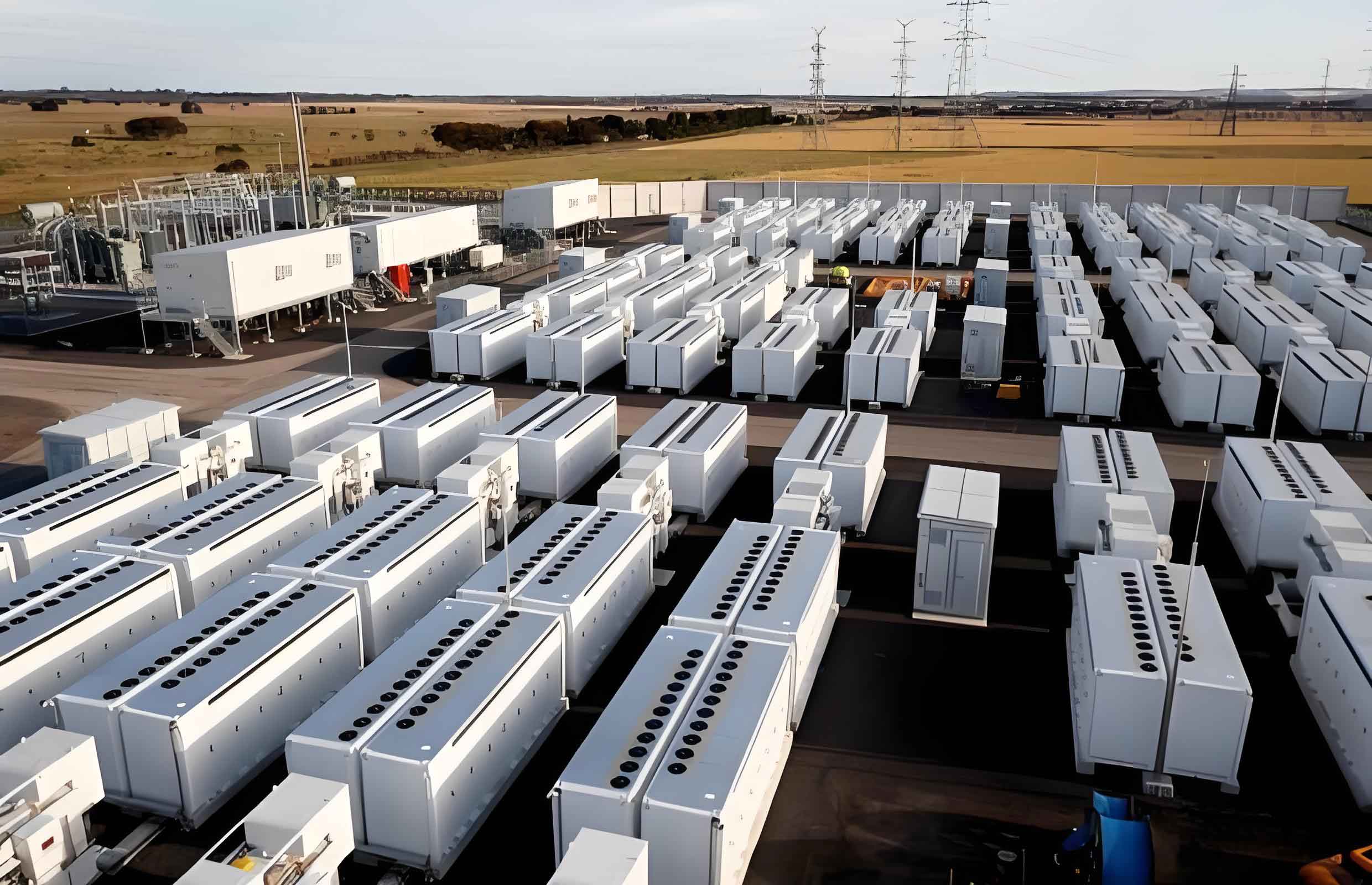
The working principle of a single distributed BESS is as follows: When a power imbalance occurs between DG and loads, the BESS injects or absorbs real power P and reactive power Q to stabilize the bus. For multiple distributed BESS, the load should be shared in proportion to each unit’s power capability, which is characterized by its SOP.
3. Coordinated Control Strategy for Distributed BESS
The overall control architecture is shown in the conceptual diagram. The bus line voltage and phase current are measured to compute the real power P, reactive power Q, and voltage amplitude Em. The SOP of each BESS is obtained from the BMS. Based on these quantities, an improved droop control generates reference angular frequency ωi and voltage amplitude Ei. A linear compensation block then adds corrections ωc and Ec to eliminate steady-state errors. The resulting ωp and Ep are used to generate the modulation index m and phase angle ψ via a PI regulator and an integrator, respectively. Finally, PWM pulses drive the PCS switches to control the output power.
3.1 Improved Droop Control Based on SOP
Traditional droop control for inductive line impedance is expressed by the following equations:
$$
\omega = \omega_0 – K_{\omega i} P_i
$$
$$
E = E_0 – K_{Ei} Q_i
$$
where ω0 and E0 are the nominal angular frequency and voltage amplitude; Kωi and KEi are the droop coefficients for the i-th BESS; Pi and Qi are the output active and reactive powers. Conventionally, the droop coefficients are determined by the rated capacities:
$$
K_{\omega i} = \frac{\Delta \omega_{\max}}{P_{\text{BESS}i\_\text{rated}}}
$$
$$
K_{Ei} = \frac{\Delta E_{\max}}{Q_{\text{BESS}i\_\text{rated}}}
$$
However, fixed coefficients cannot adapt to varying SOP values. If a BESS has a lower remaining power capability, it should contribute less load. Therefore, we define a SOP-based droop coefficient for active power:
$$
K’_{\omega i} = \frac{K_{\omega i}}{\text{SOP}_i}
$$
where SOPi is the state of power of the i-th BESS, ranging between 0 and 1. The SOP is defined in steady state as:
$$
\text{SOP} = \frac{E_{\text{limit}} (E_{\text{ocv}} – E_{\text{limit}})}{r_0 + r_1}
$$
with Elimit being the minimum battery voltage, Eocv the open-circuit voltage, and r0, r1 the equivalent resistances. The improved droop control becomes:
$$
\omega = \omega_0 – K’_{\omega i} P_i
$$
$$
E = E_0 – K_{Ei} Q_i
$$
Thus, when Pi is within the PCS capacity, the load sharing among distributed BESS units is proportional to their SOP ratios. A BESS with a higher SOP takes a larger share of the load, and vice versa.
3.2 Linear Voltage and Frequency Compensation
To mitigate the static errors and voltage drops introduced by the droop control and line impedance, we design a linear compensation loop. The voltage compensation is implemented using two cascaded PI controllers:
$$
E_c = K_{ep1} (E_0 – E_m) + K_{ei1} \int (E_0 – E_m) dt
$$
$$
m = K_{ep2} (E_c – E_m) + K_{ei2} \int (E_c – E_m) dt
$$
where m is the modulation index. The frequency compensation utilizes a proportional gain K to generate ωc:
$$
\omega_c = K (\omega_0 – \omega_m)
$$
Then the compensated angular frequency ωp = ωi + ωc and voltage amplitude Ep = Ei + Ec are used for PWM generation. This ensures zero steady-state error in voltage and frequency.
4. Simulation Results and Analysis
To validate the proposed strategy, a simulation model with two distributed BESS units, a wind turbine, and various loads (resistive, inductive, motor, and impedance loads) was built in PSCAD/EMTDC. The simulation parameters are listed in Table 1.
| Parameter | Value |
|---|---|
| System frequency F (Hz) | 50 |
| System voltage E (V) | 380 |
| BESS capacity Sd (kV·A) | 75 |
| Battery terminal voltage Ed (V) | 128 |
| Filter inductance L (μH) | 0.04 |
| Filter capacitance C (μF) | 66 |
| Kω1 (Hz/kW) | 0.01 |
| Kω2 (Hz/kW) | 0.008 |
| KE1 (Hz/(kV·A)) | 0.01 |
| KE2 (Hz/(kV·A)) | 0.008 |
| Transformer capacity ST (kV·A) | 80 |
| Motor power Pm (kW) | 30 |
| Battery capacity (BS1/BS2) Cb (A·h) | 240 |
The load sequence was: from 0 to 1 s, only 5 kW resistive load; at 1 s, a 30 kW motor started; at 2 s, a 10 kV·A inductive load was added; at 3 s, a (20+j15) kV·A impedance load was connected; at 5 s, the impedance load was disconnected; at 6 s, the inductive load was cut; at 7 s, the motor was removed. Two BESS units had different initial SOP values: SOP1 = 0.8, SOP2 = 1.0. The simulation results are shown in Figure 6 (not reproduced here). Key observations:
- The active and reactive power outputs of the two distributed BESS units followed a ratio of 0.8:1.0 (i.e., 4:5), confirming that the SOP-based droop control allocated loads proportionally.
- Battery currents also followed the SOP ratio, preventing overdischarge of the weaker unit.
- Voltage E and frequency F exhibited transient deviations during load changes but recovered to steady-state values within 0.1% and 0.5% respectively.
- The SOP values gradually equalized over time: initially ΔSOP = 0.2; after 7 s, ΔSOP reduced to 0.16, indicating balanced energy usage.
Table 2 compares the voltage and frequency deviations before and after adding the linear compensation loop.
| Metric | Without Compensation | With Compensation |
|---|---|---|
| Voltage deviation (steady-state, %) | 2.8% | 0.1% |
| Frequency deviation (steady-state, %) | 1.0% | 0.5% |
Clearly, the linear compensation loop significantly improved the voltage and frequency regulation, achieving near-zero static errors.
Figure 8 (conceptual) shows the system response during the start-up of the large motor. The motor current surged momentarily, and the battery current of BESS1 also spiked to provide the required power, then settled down. The bus voltage remained stable at 380 V, demonstrating the fast response and robustness of the proposed control.
5. Conclusion
This paper presents a coordinated control strategy for distributed battery energy storage systems based on the concept of state of power. By replacing fixed droop coefficients with SOP-dependent ones, the load sharing among multiple BESS units becomes proportional to their instantaneous power capability, avoiding overcharging or overdischarging. An outer linear compensation loop eliminates the static voltage and frequency deviations inherent in droop control. Simulation results confirm that the proposed method maintains voltage and frequency within tight limits (0.1% and 0.5%) under various load changes and motor start-ups. The strategy also promotes equalization of SOP among units, prolonging battery life. The work provides a practical approach for managing distributed BESS in microgrids and can be extended to more complex configurations with multiple energy storage systems.
The key contributions can be summarized as:
- Introduction of SOP into the droop control framework for the battery energy storage system.
- Design of a linear compensation loop to improve voltage and frequency quality.
- Validation through detailed simulations demonstrating effective load allocation and stable operation.
Future work will focus on experimental validation and integration with advanced battery management systems for real-time SOP estimation.