
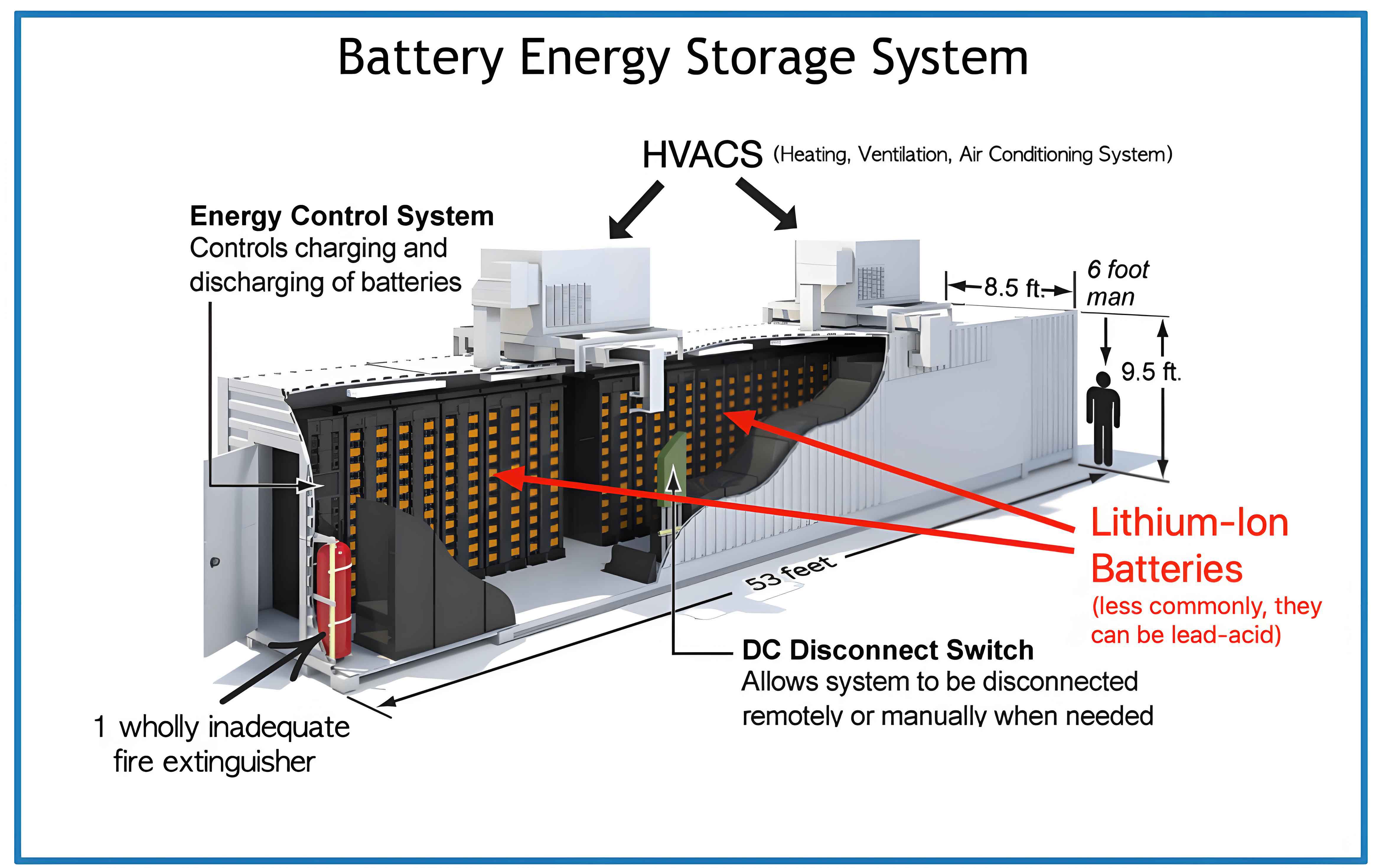
In remote island areas or off-grid regions, renewable energy sources such as solar and wind are widely adopted due to their economic and environmental benefits. However, the inherent randomness and volatility of renewable generation pose significant challenges to power supply stability. To ensure reliable operation of isolated microgrids, large-capacity energy storage systems are essential. The energy storage system interfaces with the microgrid through three-phase full-bridge converters, and its control strategy directly determines the system performance. Among various control schemes, droop control is a popular method for parallel operation of multiple energy storage units because it mimics the droop characteristics of synchronous generators. Nevertheless, conventional droop control suffers from slow dynamic response, large frequency and voltage deviations under load transients, and steady-state errors. In this paper, I propose an improved droop control strategy that dynamically adjusts the droop coefficients based on active and reactive power variations and introduces derivative terms to enhance the transient response. The proposed method is validated through simulation studies.
1. Mathematical Model of the Energy Storage System Converter
The energy storage system is typically connected to the AC grid via a three-phase full-bridge voltage source converter (VSC) that allows bidirectional power flow. The topology consists of a DC-link capacitor, a three-phase inverter, and an LCL or LC filter. The dynamic equations in the synchronous rotating dq reference frame are derived from Kirchhoff’s voltage law. Neglecting the filter capacitor in the grid-side inductor model, the voltage equations are:
$$
L \frac{di_d}{dt} = e_d – R i_d + \omega L i_q – u_d
$$
$$
L \frac{di_q}{dt} = e_q – R i_q – \omega L i_d – u_q
$$
where \(e_d, e_q\) are the dq components of the grid voltage, \(i_d, i_q\) are the dq components of the converter output current, \(u_d, u_q\) are the dq components of the converter terminal voltage, \(R\) and \(L\) are the filter resistance and inductance, and \(\omega\) is the angular frequency. This model forms the foundation for designing the inner current control loops.
2. Conventional Droop Control for Parallel Energy Storage Systems
In an islanded microgrid, multiple energy storage units operate in parallel to share the load. Droop control is implemented by adjusting the frequency and voltage magnitude of each converter as linear functions of the measured active and reactive power outputs. The conventional droop equations are:
$$
f = f_n – m P
$$
$$
U = U_n – n Q
$$
where \(f_n\) and \(U_n\) are the no-load frequency and voltage, \(P\) and \(Q\) are the measured active and reactive powers, and \(m, n\) are fixed droop coefficients. The coefficients are determined by the maximum allowable deviations:
$$
m = \frac{\Delta f}{P_{max}}, \quad n = \frac{\Delta U}{Q_{max}}
$$
The power transmission relationship between the converter output and the grid determines the coupling between frequency/voltage and power. For a mainly inductive transmission line (high-voltage or medium-voltage network), the active power is predominantly controlled by the phase angle (or frequency), while reactive power is controlled by the voltage amplitude:
$$
P \approx \frac{E V}{X} \sin\delta, \quad Q \approx \frac{V}{X}(E\cos\delta – V)
$$
For low-voltage distribution networks where resistance dominates, the coupling reverses. Therefore, conventional droop control must be applied with proper line impedance compensation, often by adding virtual impedance to ensure inductive behavior.
3. Proposed Improved Droop Control Strategy
In conventional droop control, the fixed droop coefficients \(m\) and \(n\) lead to large frequency and voltage drops under heavy load, and the low-pass filter used for power measurement introduces significant delay. To improve both steady-state and dynamic performance, I propose a modified droop control with variable coefficients and derivative terms. The improved control law is:
$$
f = f_n – (m_1 – m_2 P^2) P + m_d \frac{dP}{dt}
$$
$$
U = U_n – (n_1 – n_2 Q^2) Q + n_d \frac{dQ}{dt}
$$
where \(m_1, n_1\) are the conventional droop slopes, \(m_2, n_2\) are additional coefficients that reduce the effective droop gain as power increases, and \(m_d, n_d\) are derivative gains that accelerate the transient response. The quadratic term \(m_2 P^2\) flattens the droop curve near the rated operating point, thereby reducing frequency/voltage deviations when the load changes moderately. The derivative terms provide an immediate response to power fluctuations before the low-pass filter output settles.
The selection of \(m_2\) must ensure that the equivalent droop coefficient remains positive. A reasonable range is:
$$
0 < m_2 < \frac{m_1}{P_n^2}
$$
Similarly for \(n_2\). The derivative gains \(m_d\) and \(n_d\) are chosen based on the desired damping and response speed, typically two to three orders of magnitude smaller than the time constant of the power filter.
Compared to the conventional method, the proposed strategy reduces the steady-state frequency and voltage deviations while simultaneously improving the dynamic response. The following table summarizes the differences:
| Parameter | Conventional Droop | Improved Droop |
|---|---|---|
| Droop coefficient | Fixed \(m, n\) | Variable \(m_1 – m_2 P^2\) |
| Dynamic correction | None | Derivative terms \(m_d \, dP/dt\) |
| Low-pass filter | Required (delays response) | Reduced delay due to derivative feedforward |
| Frequency drop under load step | Large | Smaller |
| Voltage drop under load step | Large | Smaller |
| Settling time | Long | Short |
4. Simulation Results and Analysis
To verify the effectiveness of the proposed improved droop control, a simulation model of a parallel energy storage system is built using MATLAB/Simulink. The system consists of two identical 3 kVA energy storage units connected to a common AC bus through LC filters. The load is composed of three identical resistive-inductive loads that can be switched sequentially. The key parameters are listed in the table below.
| Parameter | Value |
|---|---|
| Rated power per unit | 3 kVA |
| AC bus voltage (line-to-line RMS) | 650 V |
| Rated frequency | 50 Hz |
| Filter inductance \(L\) | 8 mH |
| Filter resistance \(R\) | 0.1 Ω |
| Filter capacitance \(C\) | 5.6 μF |
| Conventional droop coefficient \(m_1\) | 0.0001 |
| Conventional droop coefficient \(n_1\) | 0.001 |
| Improved droop coefficient \(m_2\) | 3.7×10⁻¹² |
| Improved droop coefficient \(n_2\) | 6×10⁻¹⁰ |
| Derivative gain \(m_d\) | 6×10⁻⁶ |
| Derivative gain \(n_d\) | 6×10⁻⁶ |
| Load 1 (R-L) | 1500 W, 1500 var |
| Load 2 (R-L) | 1500 W, 1500 var |
| Load 3 (R-L) | 1500 W, 1500 var |
In the simulation, Load 1 is connected at t=0 s, Load 2 at t=0.2 s, and Load 3 at t=0.4 s. The frequency and voltage responses of one energy storage unit are recorded for both conventional and improved droop control. The results are described as follows.
Frequency Response: When the active power demand increases stepwise, the frequency drops. With conventional droop control, the frequency decreases by approximately 0.15 Hz after the first load step and further drops to about 0.45 Hz below nominal after the third step. The settling time is around 0.1 s. In contrast, with the proposed improved droop control, the frequency drop is reduced by about 40% (only 0.09 Hz after the first step and 0.27 Hz after the third step), and the settling time is halved to 0.05 s. The derivative term provides an immediate counteraction, resulting in a quicker recovery. The steady-state frequency deviation is also smaller due to the nonlinear droop term.
Voltage Response: Similar trends are observed for the voltage magnitude. Under reactive power loading, conventional droop causes a voltage drop of about 10 V per load step, leading to 30 V drop at full load. The improved droop limits the voltage drop to about 6 V per step, i.e., 18 V at full load. The transient overshoot is also damped more effectively.
The following table quantifies the performance improvements:
| Criteria | Conventional Droop | Improved Droop |
|---|---|---|
| Frequency drop at full load (Hz) | 0.45 | 0.27 |
| Voltage drop at full load (V) | 30 | 18 |
| Settling time for frequency (s) | 0.10 | 0.05 |
| Settling time for voltage (s) | 0.12 | 0.06 |
| Maximum frequency deviation under 50% load step (Hz) | 0.22 | 0.13 |
The simulation results clearly demonstrate that the improved droop control not only reduces the magnitude of voltage and frequency excursions but also accelerates the dynamic response. This is particularly beneficial for islanded microgrids where energy storage systems must quickly adapt to fluctuating renewable generation and load changes.
5. Discussion on Parameter Tuning
The tuning of the improved droop parameters requires careful consideration. The base droop slope (\(m_1, n_1\)) should be set according to the maximum allowable frequency/voltage deviations and the rated power of the energy storage unit. The nonlinear coefficients (\(m_2, n_2\)) are then chosen such that the effective droop slope at rated power is about 50–70% of the conventional slope to reduce steady-state error while maintaining stability. The derivative gains (\(m_d, n_d\)) are determined by the time constant of the power measurement filter. A larger derivative gain improves transient response but may introduce noise sensitivity; therefore, a low-pass filter on the derivative term is recommended. Typical values can be obtained through small-signal modeling and root-locus analysis.
6. Conclusion
In this work, I have presented an improved droop control strategy for parallel energy storage systems operating in islanded microgrids. By replacing fixed droop coefficients with power-dependent coefficients and incorporating derivative terms of active and reactive powers, the proposed method achieves better steady-state accuracy and faster dynamic response. Simulation results confirm that the frequency and voltage drops under load steps are significantly reduced, and the settling time is shortened. The improved droop control is straightforward to implement in digital controllers and can be easily integrated into existing energy storage system converters. Future work will focus on experimental validation and extension to multi-energy storage systems with state-of-charge balancing.