
The pursuit of sustainable and efficient energy conversion has positioned photovoltaic (PV) technology at the forefront of scientific and engineering innovation. Among the diverse array of PV technologies, thin film solar panels represent a critical and disruptive branch. Characterized by their remarkably thin layers of light-absorbing semiconductor materials—often just a few micrometers thick, orders of magnitude thinner than conventional crystalline silicon wafers—they offer a unique set of advantages and challenges. In this article, I will delve into the fundamental principles, material systems, manufacturing processes, and performance characteristics that define thin film solar panel technology. The core appeal of a thin film solar panel lies in its potential for lower material usage, mechanical flexibility, lightweight design, and suitability for large-area, monolithic integration, opening avenues for applications beyond traditional rigid rooftop installations, such as building-integrated photovoltaics (BIPV) and portable power systems.
The operational principle of any solar cell, including a thin film solar panel, is rooted in the photovoltaic effect. A semiconductor material absorbs photons with energy greater than its bandgap, exciting electrons from the valence band to the conduction band and thereby creating electron-hole pairs. The built-in electric field, typically established by a p-n junction or other heterostructure, then separates these charge carriers, driving them to their respective contacts and generating a photocurrent. The efficiency of this process for a thin film solar panel is governed by a complex interplay of optical absorption, charge generation, carrier transport, and charge collection.
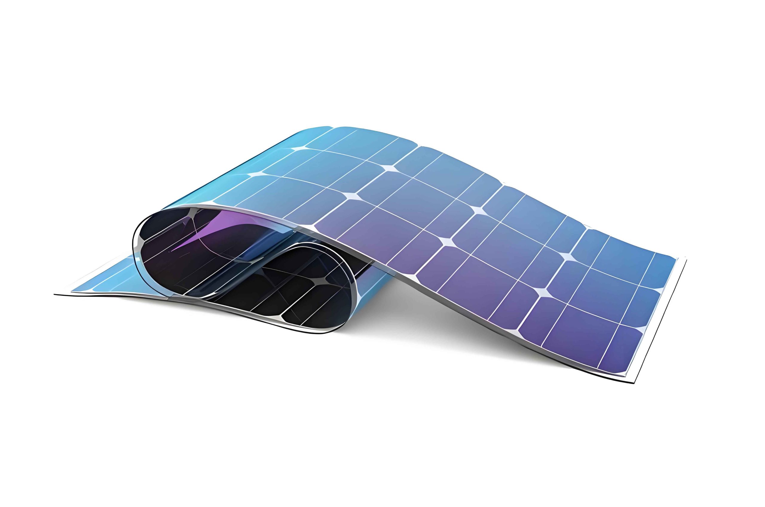
The family of thin film solar panel technologies is primarily defined by its active absorber material. Each material system offers a distinct combination of optical properties, electronic quality, stability, and cost.
| Material System | Chemical Formula / Type | Typical Bandgap (eV) | Key Advantages | Primary Challenges |
|---|---|---|---|---|
| Amorphous Silicon (a-Si) | a-Si:H | ~1.7 | Abundant, non-toxic raw materials; good low-light performance. | Light-induced degradation (Staebler-Wronski effect); relatively low efficiency. |
| Cadmium Telluride (CdTe) | CdTe | ~1.45 | Near-ideal bandgap for single-junction cells; high absorptivity; low-cost, scalable manufacturing. | Toxicity of cadmium (requires lifecycle management); limited tellurium supply. |
| Copper Indium Gallium Selenide (CIGS) | Cu(In,Ga)Se2 | 1.0–1.7 (tunable) | Highest efficiency among commercial thin films; tunable bandgap; good stability. | Complex multi-element composition; scarcity of indium; sensitive manufacturing process. |
| Gallium Arsenide (GaAs) – thin film | GaAs | ~1.42 | Exceptionally high single-junction efficiency; superior radiation resistance. | Very high material and fabrication cost; limited to niche applications (e.g., space, concentrators). |
| Emerging: Perovskites | e.g., CH3NH3PbI3 | ~1.5 (tunable) | Rapid efficiency growth; solution-processable; excellent optoelectronic properties. | Stability under heat, moisture, and light; lead toxicity concerns. |
The physics governing the performance of a thin film solar panel can be described through several key equations. The maximum theoretical efficiency limit for a single-junction cell under unconcentrated sunlight is given by the Shockley-Queisser (SQ) limit, which is a function of the semiconductor bandgap \(E_g\):
$$
\eta_{\text{max}} = \frac{J_{sc} V_{oc} FF}{P_{\text{in}}}
$$
Where \(J_{sc}\) is the short-circuit current density, \(V_{oc}\) is the open-circuit voltage, and \(FF\) is the fill factor. The \(V_{oc}\) is fundamentally limited by the bandgap and the dark saturation current \(J_0\):
$$
V_{oc} \approx \frac{n k_B T}{q} \ln\left(\frac{J_{sc}}{J_0} + 1\right)
$$
Here, \(n\) is the diode ideality factor, \(k_B\) is Boltzmann’s constant, \(T\) is temperature, and \(q\) is the elementary charge. For a thin film solar panel, achieving a high \(J_{sc}\) requires efficient light absorption across the solar spectrum. The absorption coefficient \(\alpha(\lambda)\) is crucial; a high \(\alpha\) means the material can absorb most of the above-bandgap light within a very thin layer. The photon flux absorbed, \(\Phi_{\text{abs}}\), can be approximated by:
$$
\Phi_{\text{abs}} = \int_{\lambda} \Phi_{\text{AM1.5G}}(\lambda) \left[1 – e^{-\alpha(\lambda) d}\right] d\lambda
$$
where \(\Phi_{\text{AM1.5G}}\) is the standard solar spectral flux, and \(d\) is the absorber layer thickness. A key advantage of materials like CdTe and CIGS in a thin film solar panel is their very high \(\alpha\) ( > 105 cm-1), allowing \(d\) to be just 1-3 μm, compared to the ~180 μm needed for crystalline silicon.
Manufacturing processes for thin film solar panels are fundamentally different from those for wafer-based silicon. They are typically based on vacuum deposition or solution-based coating techniques onto large-area substrates (glass, metal foil, or polymer). The most common deposition methods are summarized below:
| Deposition Method | Typical Materials | Process Characteristics | Impact on Thin Film Solar Panel |
|---|---|---|---|
| Sputtering | Metals (Mo, Al), CIGS precursors, TCOs (ITO, AZO) | High-quality, uniform films; good adhesion; scalable. | Forms back contacts and transparent conductive oxides. |
| Chemical Vapor Deposition (CVD) | a-Si, µc-Si, CdTe | Can produce high-purity, dense films; precise control over composition. | Core technique for silicon-based and CdTe absorber layers. |
| Close-Spaced Sublimation (CSS) | CdTe | High deposition rate; efficient material use. | Primary industrial method for CdTe absorber deposition. |
| Co-evaporation | CIGS | Direct control over elemental fluxes; can yield highest-quality CIGS films. | Used in lab-record and some commercial CIGS modules. |
| Solution Processing (Printing, Coating) | Perovskites, CZTS, organic PV | Very low capital cost; high material utilization; non-vacuum. | Key for emerging technologies; enables flexible, roll-to-roll manufacturing. |
A critical aspect of a high-performance thin film solar panel is the device architecture, which is more complex than a simple p-n homojunction. It often involves a heterojunction with a dedicated window layer and intricate contact schemes. A typical superstrate structure (e.g., for CdTe) is: Glass / Transparent Conductive Oxide (TCO) / n-type window layer (e.g., CdS) / p-type absorber (CdTe) / back contact. The substrate structure (common for CIGS on flexible foil) reverses this order. The interface between the window and absorber is critical, as defects here can act as recombination centers, severely limiting \(V_{oc}\) and \(FF\). The net current density \(J\) of the cell under illumination is given by the diode equation modified for photogeneration:
$$
J = J_0 \left[ \exp\left(\frac{qV}{n k_B T}\right) – 1 \right] – J_{ph}
$$
where \(J_{ph}\) is the photocurrent density. In a thin film solar panel, \(J_0\) is often higher than in high-quality single-crystal cells due to higher bulk and interface recombination, which is a primary focus of material and process optimization.
The real-world performance of a thin film solar panel module is evaluated beyond the laboratory cell efficiency. Key metrics include the temperature coefficient, spectral response, and degradation rates. Thin film panels, particularly CdTe and CIGS, often exhibit lower temperature coefficients than crystalline silicon, meaning their output power decreases less as operating temperature rises—a significant advantage in hot climates. The normalized temperature coefficient \(\beta\) for power is defined as:
$$
\beta = \frac{1}{P_{\text{STC}}} \frac{dP_{\text{max}}}{dT}
$$
where \(P_{\text{STC}}\) is the power at Standard Test Conditions (25°C). Typical values are around -0.25%/°C for crystalline silicon, but can be as low as -0.20%/°C for a well-engineered thin film solar panel. Another critical figure of merit is the energy yield over time, which accounts for spectral effects, low-light performance, and durability. The levelized cost of electricity (LCOE) is the ultimate commercial metric, and the potential for lower manufacturing costs at scale is a major driver for thin film solar panel development. LCOE can be approximated as:
$$
\text{LCOE} = \frac{\sum_{t=0}^{N} \frac{I_t + O\&M_t}{(1+r)^t}}{\sum_{t=0}^{N} \frac{E_t}{(1+r)^t}}
$$
where \(I_t\) is the investment cost in year \(t\), \(O\&M_t\) is operation and maintenance cost, \(E_t\) is the energy produced, \(r\) is the discount rate, and \(N\) is the system lifetime. The thinner material use and simpler, more integrated manufacturing process of a thin film solar panel aim to reduce the numerator, while high energy yield aims to increase the denominator.
Stability and reliability are paramount for any commercial PV technology. Thin film solar panel technologies have faced their unique challenges. a-Si suffers from the Staebler-Wronski effect, a light-induced metastable degradation that can reduce efficiency by 10-30% before stabilizing. CdTe and CIGS modules have demonstrated excellent long-term field stability, with degradation rates often below 0.5% per year, comparable to or better than silicon. This is achieved through careful encapsulation, stable contact design (e.g., copper doping and a buffer layer in CdTe), and robust module packaging. For emerging perovskite-based thin film solar panels, stability is the primary hurdle, with research focusing on encapsulation, compositional engineering (e.g., mixed cations/anions), and dimensional structuring (2D/3D perovskites) to enhance resistance to heat, moisture, and ion migration.
The future trajectory of thin film solar panel technology is directed towards higher efficiency, lower cost, and new functionalities. Tandem or multi-junction architectures represent the most direct path to surpassing the SQ limit for single junctions. A perovskite-on-silicon tandem is a highly active area, but all-thin-film tandems, such as perovskite-on-CIGS, hold immense promise for lightweight, flexible, and ultra-high-efficiency modules. The theoretical efficiency for a two-junction tandem is significantly higher:
$$
\eta_{\text{tandem, max}} \approx \eta_{\text{top}}(E_{g,\text{top}}) + \eta_{\text{bottom}}(E_{g,\text{bottom}})
$$
where the top cell absorbs high-energy photons and the bottom cell (with a lower bandgap) absorbs transmitted low-energy photons. With an ideal bandgap combination, two-junction efficiencies can exceed 40%. Integration is another frontier. The inherent flexibility and lightweight nature of many thin film solar panel technologies make them ideal for building-integrated photovoltaics (BIPV), vehicle-integrated PV (VIPV), and consumer electronics. Finally, the exploration of novel, earth-abundant, and non-toxic absorber materials like kesterites (CZTSSe: Cu2ZnSn(S,Se)4) continues, aiming to combine the sustainability of silicon with the performance and processing advantages of a thin film solar panel.
In conclusion, thin film solar panels constitute a vital and dynamic segment of the photovoltaic landscape. Their defining characteristic—the use of ultrathin layers of semiconductor materials—enables a distinct value proposition centered on material economy, manufacturing scalability, and application versatility. From the mature, utility-scale deployments of CdTe to the high-efficiency promise of CIGS and the meteoric rise of perovskite photovoltaics, the technology continues to evolve. The physics of light absorption, carrier generation, and recombination in these thin layers presents both challenges and opportunities for innovation. Continued advancements in materials science, interface engineering, and large-scale deposition processes will determine the role of the thin film solar panel in the global transition to a sustainable energy future. Their potential to achieve low levelized cost of electricity while enabling new, integrated applications ensures they will remain a critical focus of research and development for years to come.