
In the pursuit of sustainable and cost-effective renewable energy sources, thin film solar panel technology has emerged as a leading contender. Unlike their crystalline silicon counterparts, thin film solar panels offer advantages such as lower material consumption, flexibility, and the potential for large-area, low-temperature manufacturing. Among the various thin film photovoltaic (PV) technologies, copper-based compound absorbers, including Cu(In,Ga)Se2 (CIGS) and Cu2ZnSn(S,Se)4 (CZTSSe), have demonstrated remarkable power conversion efficiencies, exceeding 22% and 12.6% in laboratory settings, respectively. The high efficiency, excellent stability, and strong radiation resistance of these copper-based devices underscore their significant potential in the future thin film solar panel market.
The typical device architecture of a copper-based thin film solar panel is a multilayer stack consisting of a substrate, back contact, p-type absorber layer, n-type buffer layer, window layer, and front transparent conductive oxide (TCO) grid. The window layer plays a critically decisive role in the overall device performance. It primarily comprises two sub-layers: a high-resistivity intrinsic (i-) layer and a low-resistivity, highly conductive TCO layer. The i-ZnO layer, the focus of this investigation, serves multiple vital functions. First, it acts as a physical and electronic spacer between the buffer layer and the front TCO, effectively preventing shunting paths that could drastically reduce the fill factor and open-circuit voltage. Second, it helps to minimize interface recombination losses by passivating surface states at the buffer layer interface. Third, it serves as an excellent seed or template layer for the subsequent deposition of high-quality doped ZnO (e.g., Al-doped ZnO, AZO) TCO films, which are essential for lateral current collection with minimal optical absorption. Therefore, optimizing the structural, electrical, and optical properties of the intrinsic ZnO window layer is paramount for maximizing the performance of the complete thin film solar panel.
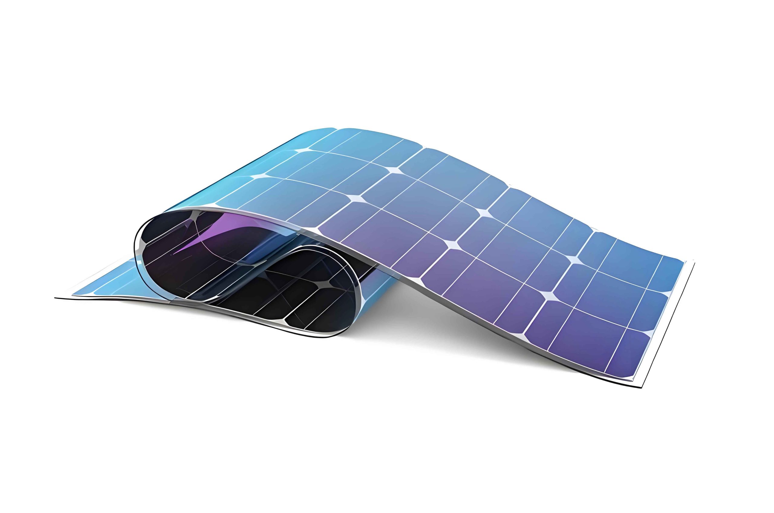
Zinc oxide (ZnO), a wide bandgap (~3.3 eV) semiconductor with a hexagonal wurtzite crystal structure, is the ideal material for this application due to its high transparency in the visible spectrum, natural n-type conductivity (often from native defects like oxygen vacancies or zinc interstitials), and good chemical stability. For optimal integration into a thin film solar panel, the i-ZnO layer must satisfy a stringent set of criteria: high optical transmittance (>85%) across the solar spectrum to allow maximum light penetration to the absorber; a moderate resistivity, typically achieved by maintaining a low free carrier concentration (on the order of 1016 cm-3 or lower) to reduce carrier recombination at the interface; and a high carrier mobility to ensure efficient lateral transport within the layer itself before collection by the front electrode. Achieving this delicate balance—low carrier concentration without compromising crystallinity and mobility—is a central challenge in film deposition.
Various techniques exist for depositing ZnO thin films, including sputtering, pulsed laser deposition (PLD), chemical vapor deposition (CVD), and sol-gel processing. Among these, magnetron sputtering stands out as the most industrially relevant and scalable technique for manufacturing large-area thin film solar panels. It offers excellent film uniformity, high deposition rates, good adhesion to substrates, and precise control over film composition and microstructure. Reactive sputtering from a metallic Zn target or sputtering from a ceramic ZnO target are common approaches. Pulsed DC magnetron sputtering, in particular, is advantageous for depositing insulating or semi-insulating oxide films like intrinsic ZnO, as it effectively mitigates arcing and target poisoning issues common in reactive DC sputtering, leading to more stable and reproducible deposition processes.
However, sputter-deposited films often exhibit high defect densities “frozen” into the growing film due to the non-equilibrium nature of the process and the high kinetic energy of arriving species. This frequently results in ZnO films with excessive free carrier concentrations (>>1017 cm-3), primarily originating from oxygen vacancies (VO) and/or zinc interstitials (Zni), which are detrimental to the device’s junction quality. Therefore, a systematic investigation of the deposition parameters that govern the film’s defect chemistry, crystallinity, and ultimately its electronic properties is essential. Two of the most critical parameters in reactive or oxygen-assisted sputtering are the substrate temperature (Ts) and the oxygen partial pressure, often expressed as the O2/(O2+Ar) flow ratio (RO). Ts controls the adatom mobility on the growing surface, influencing grain growth, crystallographic orientation, and defect annihilation. RO directly controls the oxidizing potential of the plasma, which determines the concentration of oxygen-related defects (like VO) and hence the film’s electrical conductivity.
This article presents a comprehensive, first-person study focused on the deposition and characterization of intrinsic ZnO thin films using pulsed DC magnetron sputtering from a ceramic ZnO target. We systematically investigate the influence of substrate temperature and O2/(O2+Ar) flow ratio on the structural, morphological, electrical, and optical properties of the films. Our goal is to establish a process-property relationship that guides the optimization of ZnO films specifically tailored for use as high-performance window layers in copper-based thin film solar panels. We employ a suite of characterization techniques, including X-ray diffraction (XRD), atomic force microscopy (AFM), Hall effect measurements, and UV-Vis spectroscopy, to fully elucidate the films’ properties. The insights gained are crucial for advancing the manufacturing science behind high-efficiency, large-area thin film solar panels.
1. Experimental Methodology: Pulsed DC Magnetron Sputtering and Characterization
All ZnO thin films in this study were deposited using a custom-designed, high-vacuum pulsed DC magnetron sputtering system. The primary goal was to understand the parametric effects while maintaining other variables constant to isolate the influence of substrate temperature and oxygen content. The substrate used was commercially available soda-lime glass, chosen for its low cost and relevance to industrial thin film solar panel production. Prior to deposition, the glass substrates underwent a rigorous cleaning procedure: sequential ultrasonic baths in diluted hydrochloric acid, deionized water, and absolute ethanol, each for 15 minutes, followed by drying under a stream of pure nitrogen gas.
The sputtering target was a high-purity (99.99%) ceramic ZnO plate. The use of a ceramic target, as opposed to reactive sputtering from a Zn metal target, provides greater process stability and reproducibility, which is vital for manufacturing consistent thin film solar panel components. The base pressure of the deposition chamber was evacuated to a level below 3.0 × 10⁻³ Pa to minimize contamination from residual gases. The working gas mixture consisted of high-purity argon (Ar, 99.999%) and oxygen (O2, 99.999%). The total gas pressure was maintained constant at 0.8 Pa for all depositions. The pulsed DC power supply was operated at a fixed frequency of 100 kHz with a pulse reverse time of 1 μs, which effectively discharges the target surface and prevents arcing.
The two independent variables in this study were:
- Substrate Temperature (Ts): Varied from 200°C to 350°C in 50°C increments. The temperature was controlled using a radiative heater with a feedback system and was allowed to stabilize for 30 minutes before commencing deposition.
- O2/(O2+Ar) Flow Ratio (RO): Varied from 0% (pure Ar) to 66.7% (O2:Ar flow rates of 20:10 sccm). The total gas flow (Ar+O2) was kept constant at 30 standard cubic centimeters per minute (sccm) for all experiments.
All other deposition parameters were held constant, as summarized in Table 1 below. The film thickness was carefully controlled to be 220 ± 5 nm for all samples by adjusting the deposition time accordingly. Maintaining a constant thickness is crucial for a fair comparison of optical and electrical properties, as these properties can be thickness-dependent.
| Deposition Parameter | Value / Condition |
|---|---|
| Target Material | ZnO Ceramic (99.99%) |
| Base Pressure | < 3.0 × 10⁻³ Pa |
| Working Pressure | 0.8 Pa |
| Sputtering Power Mode | Pulsed DC |
| Pulse Frequency | 100 kHz |
| Pulse Reverse Time | 1 μs |
| Target-to-Substrate Distance | 110 mm |
| Total Gas Flow (Ar+O2) | 30 sccm |
| Final Film Thickness | 220 ± 5 nm |
The deposited films were characterized using the following techniques:
- Thickness: Measured using a surface profilometer (Dektak 6M).
- Structure and Crystallinity: Analyzed by X-ray diffraction (XRD, PANalytical Empyrean) with Cu Kα radiation (λ = 1.54056 Å) in a θ-2θ scanning mode. The scan range was from 20° to 60° with a step size of 0.05°.
- Surface Morphology: Investigated by atomic force microscopy (AFM, Bruker Multimode 8) in tapping mode over a scan area of 2 μm × 2 μm. The root-mean-square (RMS) roughness was extracted from the AFM data.
- Electrical Properties: Determined by Hall effect measurements (HL5500 system) at room temperature using the van der Pauw configuration with indium dot contacts.
- Optical Properties: Evaluated using ultraviolet-visible (UV-Vis) spectroscopy (Hitachi U-3310) in the wavelength range of 300-900 nm. The optical band gap was derived from the transmittance data.
The systematic application of these characterization methods allows us to build a complete picture of how processing conditions affect the material properties relevant to a thin film solar panel window layer.
2. Influence of Substrate Temperature on ZnO Thin Film Properties
Substrate temperature is a fundamental parameter in thin film growth, governing the kinetics of surface diffusion, nucleation, and grain growth. For the window layer of a thin film solar panel, the microstructure dictated by Ts profoundly influences electrical transport and optical scattering.
2.1 Structural and Morphological Evolution
The XRD θ-2θ patterns for ZnO films deposited at different substrate temperatures, with a fixed RO of 66.7%, are shown below. All patterns are dominated by a single, strong diffraction peak located at approximately 34.4°. This peak corresponds to the (002) plane of the hexagonal wurtzite structure of ZnO (JCPDS card no. 36-1451). The conspicuous absence of other peaks, such as (100) or (101), indicates a strong preferential orientation with the c-axis perpendicular to the substrate plane. This c-axis orientation is highly desirable for transparent conductive oxides in thin film solar panels as it often correlates with higher electron mobility along the conductive basal plane.
A detailed analysis reveals that the intensity of the (002) peak increases monotonically with increasing Ts. This signifies an improvement in the overall crystallinity and/or the degree of preferred orientation. Atoms arriving at the substrate surface possess higher thermal energy at elevated temperatures, enabling them to diffuse to lower-energy lattice sites and promoting the growth of better-ordered, larger crystalline domains aligned with the thermodynamically favored c-axis orientation.
We can quantify the crystallite size (D) along the [002] direction using the Debye-Scherrer formula:
$$ D = \frac{0.89 \lambda}{\beta \cos\theta} $$
where λ is the X-ray wavelength (1.54056 Å), β is the full width at half maximum (FWHM) of the (002) peak in radians, and θ is the Bragg angle. The calculated crystallite sizes and corresponding FWHM values are summarized in Table 2. The clear trend of increasing crystallite size (from ~24 nm to ~32 nm) and decreasing FWHM with increasing Ts quantitatively confirms the enhancement in crystalline quality. This growth in grain size is a direct consequence of enhanced surface and grain boundary mobility at higher temperatures.
| Substrate Temp. Ts (°C) | (002) Peak Position 2θ (°) | FWHM β (°) | Crystallite Size D (nm) |
|---|---|---|---|
| 200 | 34.32 | 0.348 | 23.8 |
| 250 | 34.36 | 0.322 | 25.7 |
| 300 | 34.38 | 0.301 | 27.5 |
| 350 | 34.40 | 0.267 | 31.9 |
The surface morphology, as revealed by AFM, correlates directly with the XRD findings. The films deposited at lower temperatures (200°C) exhibit a relatively smooth, fine-grained surface. As Ts increases to 350°C, the AFM images show a clear coarsening of the surface features, with well-defined, larger granular structures. This visual observation is quantified by the RMS roughness (Rq). The Rq increases systematically from approximately 2.1 nm at 200°C to 5.8 nm at 350°C. The growth of larger grains inevitably leads to increased surface roughness due to the more pronounced grain boundary topography. While excessive roughness can be detrimental for subsequent layer deposition in a multilayer thin film solar panel stack, a moderate level is often acceptable and may even enhance light scattering within the device.
2.2 Electrical and Optical Properties
The electrical properties, crucial for the window layer’s function, show a distinct dependence on substrate temperature. Hall effect measurement results are compiled in Table 3. A key and encouraging observation is that the carrier concentration (n) for all films remains in the range of 3-6 × 1016 cm-3. This low concentration, ideal for a high-resistivity i-ZnO layer in a thin film solar panel, is attributed to the oxygen-rich deposition condition (RO=66.7%), which suppresses the formation of oxygen vacancy (VO) donors.
The most significant trend is in the carrier mobility (μ). It increases substantially from 8.7 cm²/V·s at 200°C to 18.4 cm²/V·s at 350°C. This improvement can be directly linked to the enhanced crystallinity and larger grain size observed via XRD and AFM. In polycrystalline semiconductors, carrier transport is severely limited by scattering at grain boundaries. Larger grains mean fewer grain boundaries per unit path length. Furthermore, better crystalline quality within the grains reduces scattering from point defects and ionized impurities. The increase in mobility outweighs the slight variations in carrier concentration, leading to a net decrease in resistivity (ρ) as temperature increases. The resistivity is given by:
$$ \rho = \frac{1}{n e \mu} $$
where e is the elementary charge. The film deposited at 350°C strikes an excellent balance: a very low carrier concentration of 3.4 × 1016 cm-3 and a high mobility of 18.4 cm²/V·s, resulting in a resistivity suitable for an effective window layer in a high-performance thin film solar panel.
| Ts (°C) | Resistivity ρ (Ω·cm) | Carrier Concentration n (cm-3) | Mobility μ (cm²/V·s) |
|---|---|---|---|
| 200 | 24.1 | 5.9 × 10¹⁶ | 8.7 |
| 250 | 12.5 | 4.8 × 10¹⁶ | 10.4 |
| 300 | 8.3 | 4.2 × 10¹⁶ | 17.9 |
| 350 | 9.9 | 3.4 × 10¹⁶ | 18.4 |
The optical transmittance spectra for all films show excellent performance in the visible region (400-800 nm), with average transmittance values exceeding 90%. This high transparency is non-negotiable for any layer in the light path of a thin film solar panel. The sharp absorption edge near 375 nm corresponds to the fundamental bandgap absorption of ZnO. The optical band gap (Eg) can be determined from the transmittance (T) data by applying the Tauc plot method for direct bandgap semiconductors. The absorption coefficient (α) is first calculated from T, assuming negligible reflection:
$$ \alpha = \frac{1}{d} \ln\left(\frac{1}{T}\right) $$
where d is the film thickness. The band gap is then found by extrapolating the linear region of the (αhν)² vs. hν plot to zero:
$$ (\alpha h \nu)^2 = A (h \nu – E_g) $$
where hν is the photon energy and A is a constant. The calculated Eg values are around 3.28-3.30 eV for all films, showing no systematic variation with Ts. This indicates that the primary effect of substrate temperature is on the film’s microstructure and defect density, not on its fundamental electronic band structure.
3. Influence of O2/(O2+Ar) Flow Ratio on ZnO Thin Film Properties
While substrate temperature controls morphology, the oxygen partial pressure during sputtering is the primary knob for tuning the film’s defect chemistry and, consequently, its electrical properties. This is critical for dialing in the exact resistivity required for the i-ZnO layer in a thin film solar panel.
3.1 Structural Response to Oxygen Content
XRD patterns of films deposited at a fixed Ts of 300°C with varying RO from 0% to 66.7% are analyzed. All films retain the hexagonal wurtzite structure with a strong (002) preferential orientation. Interestingly, unlike the strong dependence on temperature, the crystalline quality as inferred from the (002) peak intensity and FWHM shows no dramatic or systematic change with increasing oxygen flow ratio. The crystallite sizes remain in a relatively narrow range of 26-29 nm. This suggests that within this parameter space, the oxygen content in the plasma does not significantly alter the nucleation and growth kinetics or the final grain size. The primary role of oxygen is chemical rather than structural, affecting the point defect population within the established crystalline lattice.
3.2 Dramatic Tuning of Electrical and Optical Properties
The impact of RO on electrical properties is profound and directly addresses the core challenge of achieving low carrier concentration. The results, detailed in Table 4, reveal a clear and powerful trend.
| RO (%) | Resistivity ρ (Ω·cm) | Carrier Concentration n (cm-3) | Mobility μ (cm²/V·s) |
|---|---|---|---|
| 0 (Pure Ar) | 6.2 × 10⁻³ | 8.7 × 10¹⁹ | 11.5 |
| 33.3 | 1.5 | 3.1 × 10¹⁷ | 13.4 |
| 50.0 | 5.8 | 6.5 × 10¹⁶ | 16.5 |
| 66.7 | 8.3 | 4.2 × 10¹⁶ | 17.9 |
The film deposited in pure Ar (RO = 0%) is highly conductive, with a carrier concentration approaching 1020 cm-3. This is characteristic of as-sputtered ZnO and is primarily due to a high density of intrinsic donor defects, namely doubly charged oxygen vacancies (VO2+) and/or zinc interstitials (Zni+), formed under oxygen-deficient conditions. Introducing even a small amount of oxygen (RO = 33.3%) into the sputtering gas causes the carrier concentration to drop by over two orders of magnitude to ~1017 cm-3. This occurs because the oxidizing plasma environment reduces the formation probability of VO and may even passivate existing ones. As RO is increased further to 50% and 66.7%, the carrier concentration decreases further to the optimal mid-1016 cm-3 range. This precise control over n is exactly what is needed for optimizing the thin film solar panel junction.
The carrier mobility shows a modest increase with RO, likely due to a reduction in ionized impurity scattering as the concentration of ionized donor defects (VO) decreases. The combined effect of drastically falling n and slightly rising μ leads to a steep increase in resistivity by nearly four orders of magnitude as RO goes from 0% to 66.7%.
The optical transmittance remains excellent (>90% average) across all RO values. However, a detailed analysis of the absorption edge reveals a notable phenomenon. The optical band gap, Eg, extracted from Tauc plots, shows a systematic decrease from approximately 3.34 eV for the film deposited in pure Ar to 3.28 eV for the film deposited at RO=66.7%. This is a classic manifestation of the Burstein-Moss effect. In highly degenerate n-type semiconductors (like the film with n ~1020 cm-3), the Fermi level lies within the conduction band. The lowest states in the conduction band are filled with electrons. Optical transitions must now occur from the valence band to empty states higher up in the conduction band, requiring higher photon energy and thus leading to an apparent widening of the optical band gap. As the carrier concentration is reduced by adding oxygen, the Fermi level moves down towards the conduction band minimum, the Burstein-Moss shift diminishes, and the measured Eg approaches the true, intrinsic band gap of ZnO (~3.3 eV). This optical measurement provides independent confirmation of the drastic changes in electronic structure governed by the oxygen flow ratio.
4. Synthesis and Optimization for Thin Film Solar Panel Application
The results from this parametric study allow us to construct a coherent picture of the growth-process-property relationships for sputtered i-ZnO films and define an optimization pathway for their use in thin film solar panels.
The substrate temperature and oxygen flow ratio are largely decoupled in their primary effects: Ts dominantly controls the microstructure (grain size, roughness, crystalline quality), while RO dominantly controls the defect chemistry and carrier concentration. This decoupling is advantageous for process optimization. We can independently tune the film’s morphology and its resistivity.
For the window layer in a copper-based thin film solar panel, the target properties are: high visible transmittance, carrier concentration in the range of 1016 cm-3, and the highest possible mobility to ensure good lateral conductivity even with low n. Our data indicates a clear optimization strategy:
- Use a High Oxygen Flow Ratio (RO > 50%): This is non-negotiable for achieving the required low carrier concentration. An oxygen-rich environment is essential to suppress oxygen vacancy formation and produce the high-resistivity i-ZnO layer. The optimal RO in our system lies between 50% and 66.7%.
- Employ a Moderately High Substrate Temperature (Ts ~ 300-350°C): While the oxygen ratio sets the carrier concentration, the substrate temperature determines the mobility. Higher temperatures (within the thermal budget of the substrate and underlying layers in the thin film solar panel stack) promote larger grain growth and better crystallinity, which directly translate to higher carrier mobility. The film deposited at Ts=350°C and RO=66.7% exemplifies the optimal combination: n = 3.4 × 1016 cm-3 and μ = 18.4 cm²/V·s.
The interplay can be summarized with the following conceptual equations representing the key film properties as functions of the process parameters:
$$ \text{Crystallite Size } D \propto f(T_s) \quad \text{(strong),} \quad g(R_O) \quad \text{(weak)} $$
$$ \text{Carrier Concentration } n \propto f'(T_s) \quad \text{(weak),} \quad g'(R_O) \quad \text{(strong, inverse)} $$
$$ \text{Carrier Mobility } \mu \propto D – \Gamma(n) $$
where Γ(n) represents scattering mechanisms related to ionized impurity concentration. High Ts increases D, and high RO decreases n, both actions contributing to higher μ.
The high optical transmittance, a basic requirement, was consistently achieved across all parameter sets, confirming the suitability of the sputtering process for depositing transparent layers. The slight increase in surface roughness at higher Ts must be considered in the context of the full device. While excessive roughness can lead to problematic shunts or poor coverage by subsequent layers, a modest roughness can be beneficial by introducing light-scattering at the i-ZnO/TCO interface, potentially trapping more light within the absorber layer of the thin film solar panel.
5. Conclusion and Outlook
In this comprehensive study, we have successfully demonstrated the controlled deposition and property tuning of intrinsic ZnO thin films via pulsed DC magnetron sputtering for application as window layers in copper-based thin film solar panels. Through systematic variation of substrate temperature (Ts) and O2/(O2+Ar) flow ratio (RO), we have elucidated the distinct and complementary roles these parameters play.
Substrate temperature is the key driver for microstructural evolution. Increasing Ts from 200°C to 350°C promotes c-axis oriented growth, increases crystallite size from ~24 nm to ~32 nm, and increases surface RMS roughness. This improvement in crystallinity directly enhances the electron mobility from 8.7 to 18.4 cm²/V·s, which is crucial for efficient carrier transport in the device. The oxygen flow ratio is the primary control knob for electronic properties. Increasing RO from 0% to 66.7% dramatically reduces the free carrier concentration by over three orders of magnitude (from ~1020 cm-3 to ~1016 cm-3) by suppressing the formation of oxygen vacancy donors. All films maintained excellent optical transparency, with average visible transmittance exceeding 90%.
The optimal film properties for a thin film solar panel window layer—low carrier concentration (~3×1016 cm-3) combined with high mobility (~18 cm²/V·s)—were achieved at a substrate temperature of 350°C and an O2/(O2+Ar) flow ratio of 66.7%. This film represents an ideal high-resistivity buffer between the absorber and the front TCO contact, capable of minimizing shunt paths and interface recombination while providing a high-quality template for the subsequent deposition of the conductive top electrode.
This work provides a clear and actionable framework for optimizing the i-ZnO layer in industrial sputtering processes. Future work will involve integrating these optimized ZnO films into complete CIGS or CZTSSe thin film solar panel device stacks to directly correlate the window layer properties with final photovoltaic performance metrics such as open-circuit voltage, fill factor, and conversion efficiency. Further studies could also explore the role of post-deposition annealing in different atmospheres to fine-tune the defect structure and the impact of very high RO ratios on film stoichiometry and growth rate. The insights gained here are a significant step towards the reproducible and high-yield manufacturing of high-efficiency, low-cost thin film solar panels.