
As a researcher deeply immersed in the field of photovoltaics, I find the rapid progress in thin film solar panels, particularly those based on copper indium gallium selenide (CIGS), to be a fascinating area of study. The efficiency records for CIGS-based thin film solar panels have seen remarkable breakthroughs, reaching over 22% in recent years. This underscores the potential of thin film solar panels as a key technology for sustainable energy. In this article, I will delve into the theoretical underpinnings of CIGS thin film solar panels, exploring their photoelectric conversion mechanisms, material properties, and device optimization strategies. My goal is to provide a comprehensive analysis that highlights why thin film solar panels, especially CIGS variants, are pivotal in the renewable energy landscape.
The fundamental principle behind thin film solar panels is the photoelectric effect, where photons with energy above a certain threshold excite electrons in a material, generating an electric current. This process converts light energy into electrical energy, forming the basis of all solar cells. In semiconductors, the energy band structure plays a crucial role. Conductors have a small bandgap, allowing easy electron excitation, while insulators have a large bandgap, preventing such transitions. Semiconductors, like those used in thin film solar panels, have an intermediate bandgap, enabling controlled charge carrier generation. When p-type and n-type semiconductors are joined, a pn junction forms due to carrier diffusion and drift, creating an internal electric field. This junction is the heart of thin film solar panels, facilitating charge separation and collection.
In CIGS thin film solar panels, the active layer is a chalcopyrite-structured semiconductor derived from copper indium selenide (CIS). The crystal structure is tetrahedral, similar to zinc blende, with copper and indium/gallium atoms replacing zinc positions. This structure imparts unique electronic properties to thin film solar panels. The bandgap of CIS is approximately 1.04 eV, but with the incorporation of gallium (Ga), forming CIGS, the bandgap increases, reaching up to 1.65 eV for copper gallium selenide (CGS). The bandgap engineering in thin film solar panels is critical for optimizing light absorption and carrier collection. The relationship between Ga content and bandgap can be expressed as: $$E_g(x) = (1 – x) \cdot E_{g,CIS} + x \cdot E_{g,CGS} + b \cdot x \cdot (1 – x)$$ where \(x\) is the Ga/(In+Ga) ratio, \(E_{g,CIS}\) is the bandgap of CIS, \(E_{g,CGS}\) is the bandgap of CGS, and \(b\) is a bowing parameter. This tunability makes thin film solar panels highly adaptable to different solar spectra.
The phase diagram of CIGS materials reveals several stable phases, including the α-phase (chalcopyrite), β-phase (CuIn3Se5), γ-phase (CuIn5Se8), and δ-phase (zinc blende). The existence of ordered defect compounds (ODCs), such as the β and γ phases, enhances the tolerance of thin film solar panels to stoichiometric deviations. This is a key advantage for manufacturing robust thin film solar panels. The primary point defects in CIGS include vacancies (e.g., VCu, VSe) and antisite defects (e.g., CuIn, InCu). These defects influence the conductivity type: VCu acts as an acceptor, leading to p-type behavior, while InCu acts as a donor, leading to n-type behavior. The defect chemistry in thin film solar panels can be summarized using the following equations for defect formation energies: $$\Delta G_f(V_{Cu}) = E_{V_{Cu}} – \mu_{Cu} + \mu_{Cu}^{bulk}$$ $$\Delta G_f(In_{Cu}) = E_{In_{Cu}} – \mu_{In} + \mu_{Cu}$$ where \(\Delta G_f\) is the formation energy, \(E\) is the defect energy, and \(\mu\) are chemical potentials. Controlling these defects is essential for high-performance thin film solar panels.
To better understand the material properties, I present a table summarizing key parameters of CIGS used in thin film solar panels:
| Property | Value for CIS | Value for CGS | Impact on Thin Film Solar Panels |
|---|---|---|---|
| Bandgap (eV) | 1.04 | 1.65 | Determines absorption edge and efficiency |
| Carrier Concentration (cm-3) | ~1016 (p-type) | ~1016 (p-type) | Affects conductivity and junction properties |
| Hole Mobility (cm2/Vs) | 15-200 | Similar range | Influences charge transport in thin film solar panels |
| Electron Mobility (cm2/Vs) | 90-900 | Similar range | Critical for current collection in thin film solar panels |
| Dielectric Constant (low T) | 13.6 ± 2.4 | Comparable | Affects electrostatic interactions in thin film solar panels |
| Effective Mass (me) | 0.09 (electron), 0.71 (heavy hole) | Similar trends | Impacts carrier dynamics in thin film solar panels |
Another important aspect is the bandgap gradient in CIGS thin film solar panels. Typically, a linear gradient forms during growth due to variations in Ga distribution. However, an optimized double gradient bandgap profile, as shown in studies, significantly enhances device performance. The double gradient involves a high Ga concentration near the back contact, creating a back surface field that reduces carrier recombination, and a lower Ga concentration near the front, improving light absorption. This design boosts the open-circuit voltage and fill factor in thin film solar panels. The bandgap profile can be modeled as: $$E_g(z) = E_{g,front} + (E_{g,back} – E_{g,front}) \cdot f(z)$$ where \(z\) is the depth from the front surface, and \(f(z)\) is a function describing the gradient. For double gradients, \(f(z)\) might be piecewise linear or exponential. This optimization is a cornerstone of high-efficiency thin film solar panels.
The device structure of CIGS thin film solar panels typically includes a substrate (e.g., glass or flexible foil), a molybdenum back contact, the CIGS absorber layer, a buffer layer (e.g., CdS or ZnS), a transparent conductive oxide (e.g., ZnO:Al), and a front contact. Each layer must be engineered for lattice matching, band alignment, and minimal interface defects. The pn junction forms between the p-type CIGS and n-type buffer layer. The efficiency of thin film solar panels is governed by factors like minority carrier lifetime, series resistance, and shunt resistance. The current-voltage characteristic can be expressed using the diode equation: $$J = J_0 \left( \exp\left(\frac{qV}{nkT}\right) – 1 \right) – J_{ph}$$ where \(J\) is the current density, \(J_0\) is the reverse saturation current density, \(V\) is the voltage, \(n\) is the ideality factor, \(k\) is Boltzmann’s constant, \(T\) is temperature, and \(J_{ph}\) is the photocurrent density. Minimizing \(J_0\) through defect control is vital for thin film solar panels.
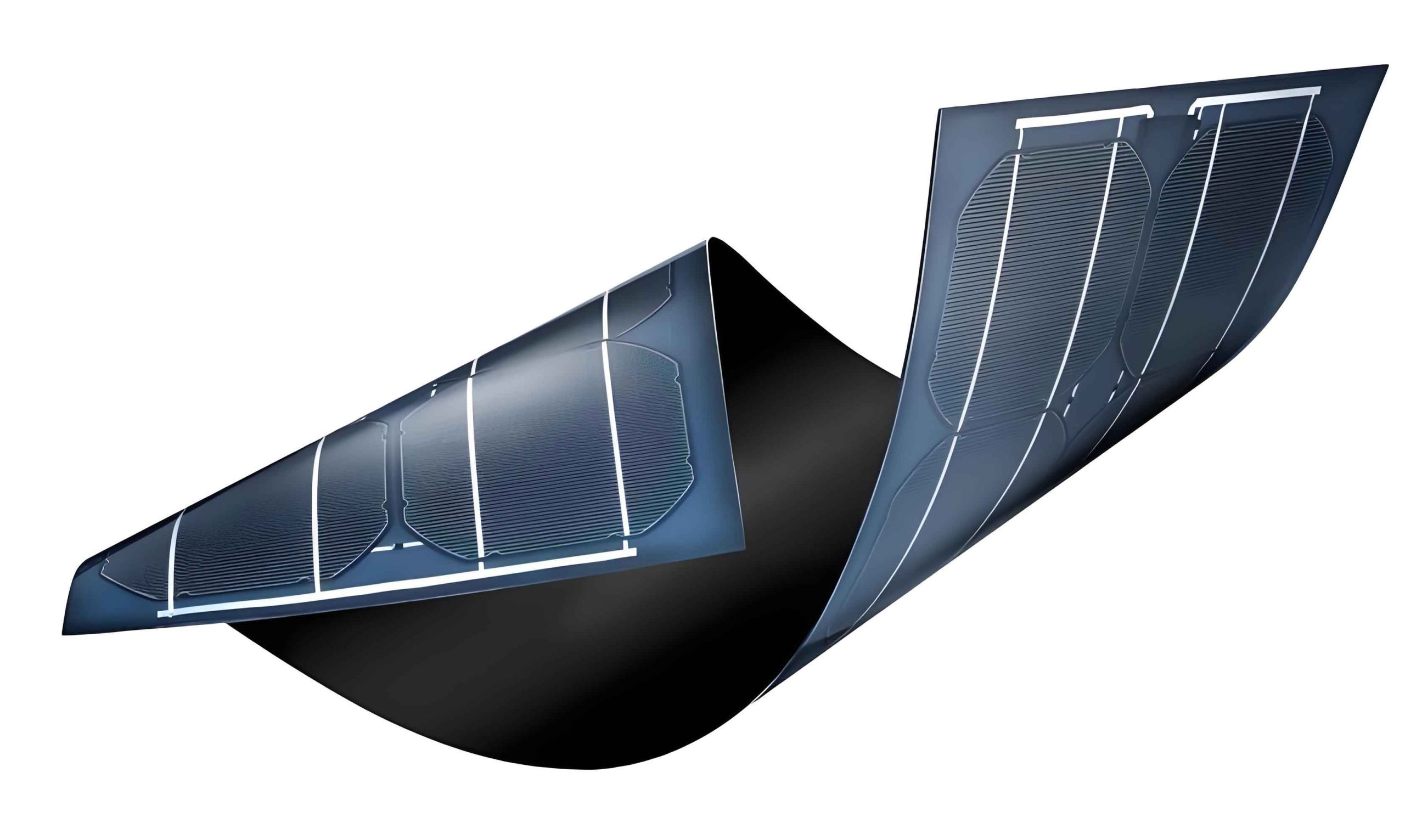
In practice, the fabrication of thin film solar panels involves deposition techniques such as co-evaporation, sputtering, or electrodeposition. The Ga/(In+Ga) ratio is typically optimized between 0.2 and 0.3 to minimize defect concentrations, as shown in experimental data. This ratio balances bandgap widening and defect formation, leading to higher efficiencies in thin film solar panels. The defect density \(N_d\) as a function of Ga ratio \(x\) can be approximated by: $$N_d(x) = N_0 \exp(-\alpha x) + \beta x(1-x)$$ where \(N_0\), \(\alpha\), and \(\beta\) are constants. Lower defect densities reduce recombination losses, enhancing the performance of thin film solar panels. Additionally, sodium incorporation from the substrate or intentional doping can further improve grain growth and conductivity in thin film solar panels.
To illustrate the impact of gradient design, consider the following table comparing linear and double gradient bandgap profiles in thin film solar panels:
| Gradient Type | Open-Circuit Voltage (V) | Short-Circuit Current (mA/cm2) | Fill Factor (%) | Efficiency (%) |
|---|---|---|---|---|
| Linear Gradient | 0.65-0.70 | 30-35 | 70-75 | 15-18 |
| Double Gradient | 0.75-0.80 | 35-40 | 75-80 | 20-22 |
The double gradient approach not only improves voltage but also current collection, making it a superior design for thin film solar panels. This is achieved by reducing interface recombination at the back contact and optimizing the electric field distribution. The electric field \(E\) in the absorber layer can be derived from the band bending: $$E(z) = -\frac{1}{q} \frac{dE_c}{dz}$$ where \(E_c\) is the conduction band edge. A tailored gradient ensures a favorable field for carrier drift, essential for efficient thin film solar panels.
Moreover, the role of ordered defect compounds (ODCs) in thin film solar panels cannot be overstated. ODCs, such as (2VCu– + InCu2+), stabilize the material against stoichiometric variations, allowing for more forgiving fabrication processes. This robustness is a significant advantage for large-scale production of thin film solar panels. The formation of ODCs can be described by quasi-chemical reactions: $$2\text{Cu}_{Cu} + \text{In}_{In} \rightleftharpoons 2V_{Cu} + \text{In}_{Cu} + 3\text{Cu} + \text{In}$$ where defects are denoted using Kröger-Vink notation. Understanding these reactions helps in designing durable thin film solar panels.
In terms of future directions, thin film solar panels based on CIGS are poised for further efficiency gains through advanced materials engineering. Concepts like bandgap grading with multiple elements, interface passivation, and light management structures are being explored. For instance, incorporating sulfur to form CIGSSe alloys can fine-tune the bandgap and reduce recombination in thin film solar panels. The bandgap of such alloys follows: $$E_{g,CIGSSe} = E_{g,CIGS} + \Delta E_{g,S} \cdot y$$ where \(y\) is the S/(Se+S) ratio. Additionally, tandem structures combining CIGS with other thin film solar panels, such as perovskite layers, could push efficiencies beyond 30%. The potential of thin film solar panels in building-integrated photovoltaics and mobile energy applications is vast, thanks to their flexibility, lightweight nature, and tunable properties.
To summarize, the theoretical foundations of CIGS thin film solar panels revolve around the chalcopyrite crystal structure, defect chemistry, and bandgap engineering. The double gradient bandgap profile, enabled by controlled Ga distribution, is a key factor in achieving high efficiencies. ODCs enhance material tolerance, while optimized device layers ensure effective charge collection. As research progresses, thin film solar panels will continue to evolve, offering a promising path toward cost-effective and efficient solar energy conversion. I believe that thin film solar panels, particularly CIGS-based systems, will play a crucial role in the global transition to renewable energy, driven by their unique theoretical and practical advantages.