
The investigation into the photoelectric characteristics of solar cells based on germanium quantum dots (Ge QDs) remains a focal point for researchers. These structures hold significant promise for the future of photovoltaics, particularly in the development of high-efficiency, cost-effective thin film solar panels. This article provides an overview of the fabrication technologies and performance optimization strategies for solar cells utilizing ultra-thin germanium quantum dot films. We will first discuss key advanced manufacturing techniques, followed by an analysis of the structural design principles and conclude with perspectives on future development pathways for enhancing module efficiency.
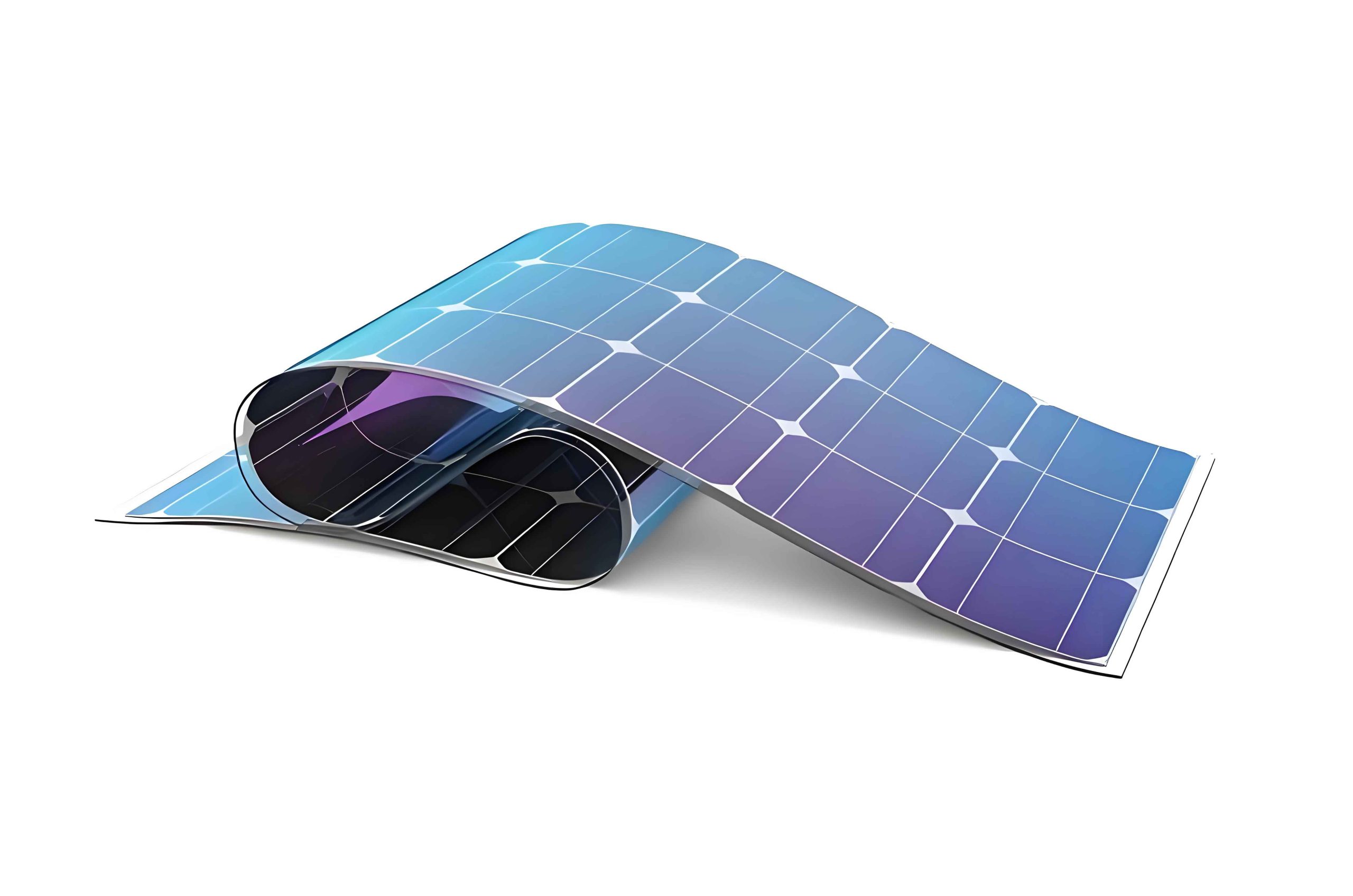
The pursuit of next-generation photovoltaic devices has led to intensive study of quantum dot-based materials. Among them, germanium quantum dots embedded in a silicon or silicon carbide matrix offer a tunable bandgap via the quantum confinement effect, described approximately by:
$$ E_g^{QD} \approx E_g^{bulk} + \frac{\hbar^2 \pi^2}{2 R^2} \left( \frac{1}{m_e^*} + \frac{1}{m_h^*} \right) $$
where $E_g^{QD}$ is the bandgap of the quantum dot, $E_g^{bulk}$ is the bulk germanium bandgap, $\hbar$ is the reduced Planck’s constant, $R$ is the radius of the quantum dot, and $m_e^*$ and $m_h^*$ are the effective masses of electrons and holes, respectively. This property allows for the tailored absorption of shorter wavelength sunlight, making Ge QD layers excellent candidates for the top or intermediate cells in multi-junction architectures, which are crucial for pushing the limits of thin film solar panels.
Fabrication Technologies for Ge QD Solar Cells
The development of high-quality Ge QD solar cells is paramount. Several sophisticated fabrication techniques have been developed to address challenges such as lattice mismatch, defect density, and current matching in multi-junction designs.
Intermediate Layer Engineering
The strategic incorporation of intermediate layers—such as intrinsic (i-) layers, buffer layers, and window layers—is critical for enhancing carrier collection and optical management in Ge QD thin film solar panels. The primary functions of these layers are summarized in the table below.
| Intermediate Layer Type | Primary Function | Impact on Cell Performance |
|---|---|---|
| Intrinsic (i-) Layer | Active light absorption region; generates electron-hole pairs. | Thickness and quality directly determine short-circuit current ($J_{sc}$) and light-induced degradation. |
| Buffer Layer | Mitigates lattice mismatch and defect propagation from the substrate. | Improves open-circuit voltage ($V_{oc}$) and fill factor ($FF$) by reducing recombination. |
| Window Layer | Provides a high-bandgap front surface for low recombination and good electrical contact. | Enhances $V_{oc}$ and $J_{sc}$ by reducing surface recombination losses. |
| Reflective/Back Layer | Reflects unabsorbed long-wavelength light back into the active layer. | Increases effective optical path length, boosting $J_{sc}$, especially in the bottom sub-cell. |
Research has shown that inserting a specifically designed reflective interlayer can simultaneously act as an optical spacer and a tunnel junction enhancer. Theoretical modeling and optical simulation are essential to find the optimal thickness ($d$) and refractive index ($n$) for these layers to maximize photon absorption in each sub-cell, thereby achieving superior current matching. The condition for constructive interference in such a layer, which enhances reflection at desired wavelengths, can be simplified as:
$$ 2 n d \cos\theta = m\lambda $$
where $m$ is an integer, $\lambda$ is the wavelength, and $\theta$ is the angle of incidence. Optimizing these parameters is key for high-performance multi-junction thin film solar panels.
Direct Bonding Technology
Direct wafer bonding is a powerful technique to circumvent the issues of lattice mismatch that typically plague heteroepitaxial growth. This process enables the integration of dissimilar semiconductor materials with optimal bandgaps for multi-junction cells without generating a high density of threading dislocations. The process typically involves:
- Surface Preparation: Achieving atomically smooth and clean surfaces (roughness < 0.5 nm) via chemical-mechanical polishing and cleaning.
- Room-Temperature Contact: Bringing the surfaces into intimate contact, allowing van der Waals forces to initiate bonding.
- Annealing: Applying heat to strengthen the bond through the formation of covalent bonds across the interface.
This technology allows for the series connection of high-quality III-V-based top cells with silicon or germanium bottom cells, creating highly efficient triple-junction structures that are relevant for both space and concentrated photovoltaic (CPV) applications. The bonding interface quality is paramount; any impurities or voids can severely degrade the electrical transport and mechanical integrity of the final thin film solar panel structure.
Tunnel Junction and High-Concentration Integration
For multi-junction cells, low-resistance, optically transparent tunnel junctions are essential for connecting sub-cells in series. Furthermore, operating under high solar concentration (e.g., 500+ suns) significantly boosts the power output and efficiency but demands excellent heat dissipation and low series resistance. The current density ($J$) through a tunnel junction under high bias can be modeled, and its resistance must be minimized to avoid power losses:
$$ P_{loss} = J^2 \cdot R_{TJ} $$
where $R_{TJ}$ is the resistance of the tunnel junction. Advanced designs using heavily doped layers and specific material combinations are continuously developed to meet these demands for concentrator thin film solar panels.
Efficiency Optimization Mechanisms
Beyond fabrication, understanding and optimizing the internal physics of the device is crucial. Key mechanisms include bandgap matching, intrinsic layer design, and anti-reflection coating optimization.
The Impact of Bandgap Matching
The theoretical maximum efficiency of a multi-junction solar cell is primarily governed by the bandgap combination of its sub-cells. For a triple-junction cell with Ge as the bottom cell, the ideal top and middle cell bandgaps are approximately 1.8-1.9 eV and 1.3-1.4 eV, respectively. Mismatch leads to current limitation by the lowest-current sub-cell, reducing overall efficiency. The total current is limited by:
$$ J_{total} = \min(J_{top}, J_{middle}, J_{bottom}) $$
Therefore, engineering the absorption profile and thickness of each layer, particularly the Ge QD-based middle cell, is essential to balance the photocurrent generation across all junctions in a thin film solar panel.
Design and Influence of the Intrinsic Layer
The intrinsic layer is the heart of the photovoltaic conversion. For amorphous silicon (a-Si:H) or microcrystalline silicon (µc-Si:H) top cells in tandem with Ge-based cells, the i-layer thickness and quality are critical.
- Thickness Optimization: A thinner i-layer in the a-Si:H top cell reduces the Staebler-Wronski effect (light-induced degradation) but also lowers light absorption. An optimal balance must be found.
- High-Rate Deposition: Developing high-deposition-rate processes for device-quality µc-Si:H i-layers is key to reducing manufacturing cost and time for thin film solar panels.
- Graded Layers: Using hydrogen dilution profiling during deposition can create a graded i-layer structure, improving material quality at the interfaces and bulk, leading to higher stabilized efficiency.
Experimental studies often map efficiency ($\eta$) as a function of top and bottom i-layer thicknesses ($d_t$, $d_b$):
$$ \eta = f(d_t, d_b, \text{material quality}) $$
The goal is to find the global maximum of this function within practical constraints.
Anti-Reflection Coating (ARC) Design
Minimizing optical reflection losses is fundamental. A well-designed multi-layer ARC can dramatically increase the short-circuit current ($J_{sc}$). The reflectance ($R$) of a double-layer ARC on a substrate can be approximated at normal incidence by:
$$ R = \left| \frac{n_0 – Y}{n_0 + Y} \right|^2 $$
where $n_0$ is the refractive index of air, and $Y$ is the effective admittance of the coating stack, which depends on the thickness and refractive indices of the layers. Modern simulations optimize these parameters to minimize the weighted average reflectance across the solar spectrum. An optimal ARC can increase $J_{sc}$ by 20-30% relative to an uncoated cell, making it a vital component of any high-efficiency thin film solar panel. The table below shows a hypothetical optimization result for a double-layer ARC on a silicon-based cell.
| ARC Layer | Optimal Material (n) | Optimal Thickness (nm) | Function |
|---|---|---|---|
| Top Layer | MgF₂ (n ~1.38) | ~100 | Reduces reflection at the air-coating interface. |
| Bottom Layer | ZnO or TiO₂ (n ~2.0-2.4) | ~60 | Matches impedance between top layer and silicon cell. |
Simulations show that such a design can achieve an average reflectance below 5% in the 400-1100 nm range, directly translating to higher photocurrent.
Conclusion and Future Outlook
Significant progress has been made in the research and development of germanium quantum dot-based thin film solar panels. Advanced techniques like direct bonding and sophisticated intermediate layer engineering have paved the way for high-efficiency multi-junction devices. Continued optimization of bandgap matching through quantum dot size control, improvement of intrinsic layer quality and stability, and the design of advanced broadband anti-reflection coatings are critical research frontiers.
The future of this technology hinges on overcoming key challenges: precise control of quantum dot size and density, improved doping techniques for nanocrystalline materials, and the development of low-cost, scalable manufacturing processes. As these scientific and engineering hurdles are addressed, germanium quantum dot film technology is poised to make substantial contributions to the next wave of high-performance, cost-effective photovoltaic modules, unlocking greater potential for solar energy utilization globally.