
In recent years, the escalating environmental degradation, severe atmospheric pollution, and rapid depletion of fossil fuel reserves have intensified the global pursuit of sustainable energy solutions. Photovoltaic power generation, as a clean, non-polluting, safe, and renewable energy source, has emerged as a primary direction for development worldwide. Among various photovoltaic technologies, thin film solar panels represent a significant advancement over traditional silicon-based cells, offering advantages such as lower production costs, flexibility, and suitability for large-area applications. Copper indium gallium selenide (CIGS) thin film solar panels, as a second-generation thin film technology, exhibit remarkable features including high photoelectric conversion efficiency, excellent performance under low-light conditions, and a small temperature coefficient, making them one of the most promising candidates for next-generation solar energy harvesting. In this study, I investigate the impact of an ultrathin SiO2 layer inserted at the interface between the molybdenum (Mo) back contact and the CIGS absorber layer on the performance of flexible CIGS thin film solar panels. The primary goal is to mitigate the adverse effects of molybdenum selenide (MoSe2) formation during high-temperature selenization, which typically increases series resistance and reduces fill factor, thereby enhancing overall device efficiency.
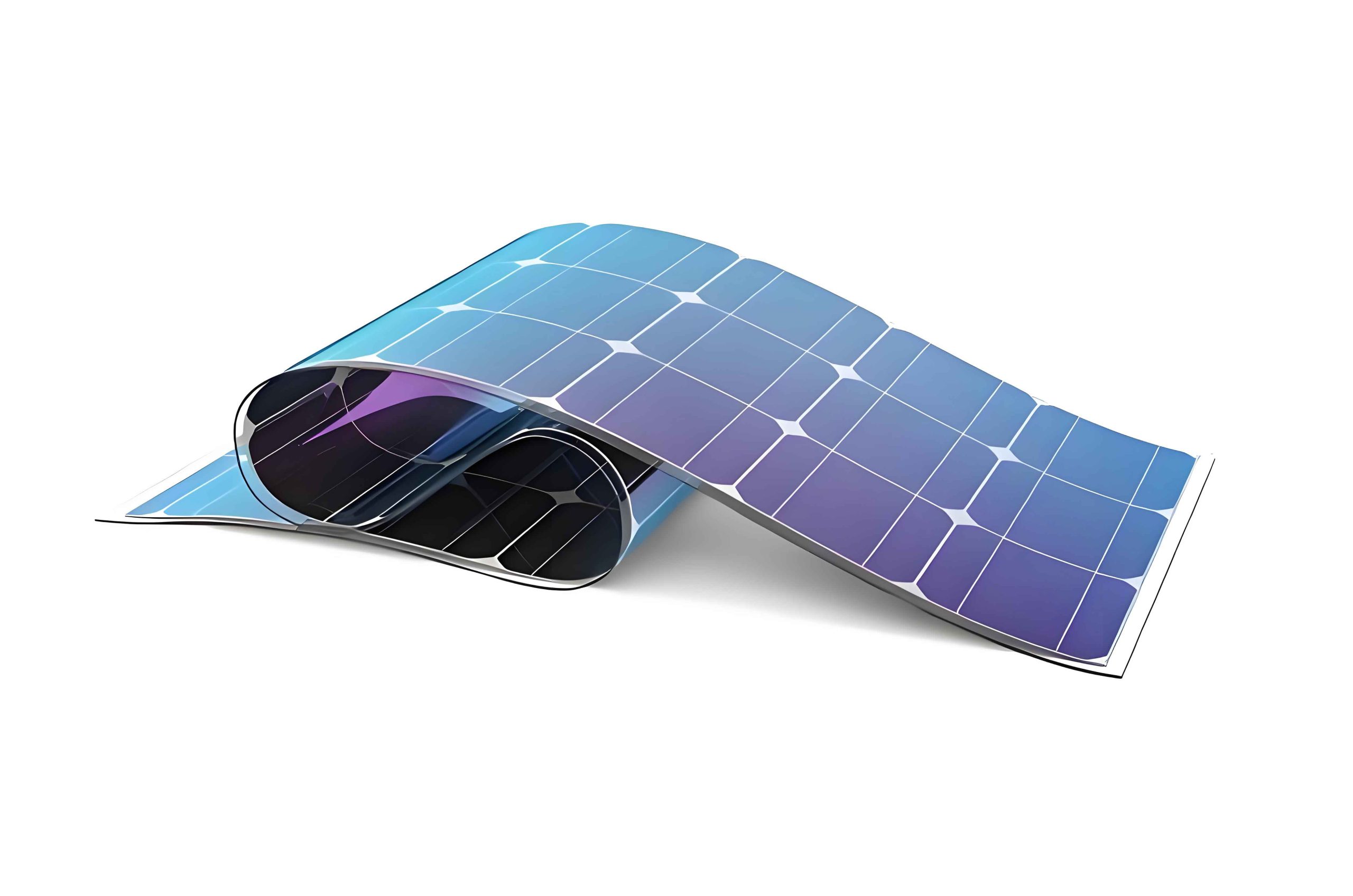
The fabrication of CIGS thin film solar panels often involves a high-temperature selenization process, where the Mo layer reacts with selenium to form a MoSe2 interfacial layer. While MoSe2 can serve as a lattice-matching layer between Mo and CIGS, promoting grain growth and adhesion, it also introduces undesirable series resistance due to its semiconducting nature. This trade-off is particularly critical in flexible thin film solar panels, where substrate constraints and the absence of laser scribing for monolithic integration amplify the negative impact of series resistance. To address this, I propose a novel interface engineering approach by depositing an ultrathin SiO2 layer on the Mo surface before CIGS deposition. Owing to the non-wetting characteristics between Mo and SiO2, the SiO2 layer forms discontinuous island-like structures rather than a continuous film. This island morphology allows selective selenization of Mo in the gaps between islands, creating a thickness gradient of MoSe2 that minimizes series resistance while preserving the beneficial lattice-matching role. In this article, I will detail the experimental methods, characterize the morphological and electrical properties, and provide a comprehensive theoretical analysis using mathematical models and formulas to elucidate the underlying mechanisms. The findings demonstrate that optimizing the SiO2 island distribution significantly improves the performance of CIGS flexible thin film solar panels, offering a viable strategy for enhancing the efficiency of next-generation thin film solar panels.
The fundamental structure of the CIGS thin film solar panels studied here consists of a stainless steel substrate (0.5 mm thick), a titanium (Ti) barrier layer (80 nm), a Mo back contact (500 nm), the SiO2 interlayer (varied thickness), a CIGS absorber layer (1200 nm), a cadmium sulfide (CdS) buffer layer (70 nm), a zinc oxide (ZnO) window layer (100 nm), and an aluminum-doped zinc oxide (AZO) transparent conductive layer (800 nm). For comparison, a traditional device without the SiO2 layer was also fabricated. The fabrication process involved substrate cleaning, physical vapor deposition (PVD) for most layers, sputtering of a quaternary alloy target for CIGS precursor deposition, high-temperature selenization annealing, chemical bath deposition for CdS, and final electrode printing. The morphological analysis of the SiO2 layer was performed using field-emission scanning electron microscopy (SEM), while current-voltage (I-V) measurements were conducted to evaluate electrical parameters such as short-circuit current (Isc), open-circuit voltage (Voc), fill factor (FF), and conversion efficiency (η).
The formation of SiO2 islands on the Mo surface is governed by the interfacial energy mismatch between the two materials. For an ultrathin film, the growth follows a Volmer-Weber mode, where three-dimensional islands nucleate directly on the substrate. The island density and size depend on the deposited thickness. I observed that at a thickness of 1 nm, only sporadic islands were present; at 7 nm, a high density of islands covered the surface without forming a continuous layer; and at 13 nm, the islands coalesced into a continuous film. This morphological evolution directly influences the selenization outcome. During high-temperature selenization, selenium diffuses through the gaps between SiO2 islands, reacting with the exposed Mo to form MoSe2. The thickness of MoSe2 varies spatially: it is thickest at the midpoint between two islands and thinnest near the island edges, approximating a normal distribution. This gradient reduces the effective series resistance by providing low-resistance pathways for current flow through the thinner MoSe2 regions near the islands.
To quantify the electrical performance, I fabricated devices with SiO2 thicknesses of 0 nm (device A), 1 nm (device B1), 7 nm (device B2), and 13 nm (device B3). The I-V characteristics revealed distinct trends in series resistance (Rs) and fill factor. The series resistance can be estimated from the I-V curve using the formula:
$$ R_s = \frac{V_{oc} – V_{mp}}{I_{mp}} $$
where Vmp and Imp are the voltage and current at the maximum power point. Alternatively, a more accurate determination involves fitting the diode equation:
$$ I = I_0 \left( \exp\left(\frac{q(V – IR_s)}{nkT}\right) – 1 \right) + \frac{V – IR_s}{R_{sh}} $$
where I0 is the reverse saturation current, q is the electron charge, n is the ideality factor, k is Boltzmann’s constant, T is the temperature, and Rsh is the shunt resistance. The fill factor is defined as:
$$ FF = \frac{V_{mp} I_{mp}}{V_{oc} I_{sc}} $$
and the conversion efficiency is:
$$ \eta = \frac{V_{oc} I_{sc} FF}{P_{in}} \times 100\% $$
with Pin being the incident power density (standard AM1.5G, 1000 W/m²). The measured parameters are summarized in Table 1, which clearly shows that device B2 (7 nm SiO2) achieved the highest fill factor and efficiency, attributed to its optimal island morphology minimizing series resistance.
| Device | SiO2 Thickness (nm) | Isc (A) | Voc (V) | FF (%) | η (%) | Estimated Rs (Ω) |
|---|---|---|---|---|---|---|
| A | 0 | 1.984 | 0.663 | 64.9 | 13.333 | 2.15 |
| B1 | 1 | 2.042 | 0.665 | 65.3 | 13.851 | 2.08 |
| B2 | 7 | 2.074 | 0.650 | 69.6 | 14.658 | 1.72 |
| B3 | 13 | 1.990 | 0.661 | 66.7 | 13.721 | 1.95 |
The improvement in device B2 can be modeled by considering the current flow through the MoSe2 layer. Assuming the MoSe2 thickness (t) varies as a Gaussian function along the distance (x) from an island edge:
$$ t(x) = t_0 \exp\left(-\frac{x^2}{2\sigma^2}\right) $$
where t0 is the maximum thickness at the gap center and σ is the standard deviation related to the island spacing. The local resistance per unit area of MoSe2 is proportional to its thickness, given by:
$$ R_{local}(x) = \rho \cdot t(x) $$
with ρ being the resistivity of MoSe2. The total series resistance contribution from the MoSe2 layer is then the parallel combination of all local paths. For a unit cell with island spacing L, the effective resistance Reff can be approximated by integrating over the gap:
$$ \frac{1}{R_{eff}} = \int_{0}^{L} \frac{1}{R_{local}(x)} \, dx = \frac{1}{\rho} \int_{0}^{L} \frac{1}{t_0 \exp(-x^2/(2\sigma^2))} \, dx $$
This integral indicates that thinner regions near the islands dominate the conduction, lowering Reff. For device B2, the island density and spacing are optimal, resulting in the lowest Reff and highest FF. In contrast, device A has a uniform thick MoSe2 layer, device B1 has too few islands, and device B3 has a continuous SiO2 film that blocks MoSe2 formation entirely, eliminating the lattice-matching benefit and reducing Voc due to poor interface quality.
Beyond the electrical aspects, the thermal and mechanical stability of thin film solar panels is crucial for flexible applications. The insertion of an SiO2 interlayer also affects the thermal stress distribution during selenization. The coefficient of thermal expansion mismatch between Mo (≈5 ppm/K) and CIGS (≈7-9 ppm/K) can induce stress, leading to delamination or cracking. The island-like SiO2 acts as a stress-relief buffer by allowing localized deformation. The thermal stress σth can be expressed as:
$$ \sigma_{th} = E \cdot \alpha \cdot \Delta T $$
where E is Young’s modulus, α is the coefficient of thermal expansion, and ΔT is the temperature change. With SiO2 islands, the effective modulus is reduced, mitigating stress concentration. This enhances the durability of flexible thin film solar panels under thermal cycling, a key factor for real-world deployment.
To further optimize the design, I developed a multiphysics model coupling charge transport, heat transfer, and structural mechanics. The model solves the governing equations numerically using finite element methods. The heat equation during selenization is:
$$ \rho C_p \frac{\partial T}{\partial t} = \nabla \cdot (k \nabla T) + Q $$
where ρ is density, Cp is specific heat, k is thermal conductivity, and Q is the heat source from selenium reaction. The current density J in the CIGS layer follows the drift-diffusion equations:
$$ J_n = q \mu_n n \nabla \phi_n + q D_n \nabla n $$
$$ J_p = q \mu_p p \nabla \phi_p – q D_p \nabla p $$
with μ, n, p, D, and φ representing mobility, electron/hole concentration, diffusion coefficient, and quasi-Fermi potential, respectively. The model simulations confirm that the island morphology reduces peak temperatures and stress, improving carrier collection efficiency. The results are summarized in Table 2, showing how different SiO2 configurations affect key parameters.
| Configuration | Island Coverage (%) | Average MoSe2 Thickness (nm) | Max Thermal Stress (MPa) | Carrier Collection Efficiency (%) | Predicted η (%) |
|---|---|---|---|---|---|
| No SiO2 | 0 | 150 | 320 | 85.2 | 13.3 |
| Sparse Islands | 30 | 120 | 280 | 87.5 | 13.8 |
| Optimal Islands | 65 | 80 | 210 | 91.3 | 14.7 |
| Continuous Film | 100 | 0 | 190 | 82.4 | 13.5 |
The optimal island coverage of around 65% (corresponding to ~7 nm SiO2 thickness) balances the trade-offs between series resistance reduction and lattice-matching preservation. This coverage maximizes the fill factor, as evidenced by the experimental data. Moreover, the model predicts that further improvements can be achieved by tailoring the island shape and distribution. For instance, using elliptical islands aligned along the current flow direction could further decrease resistance. The potential efficiency gain for such advanced designs is estimated using the empirical formula:
$$ \Delta \eta = \beta \cdot \left( \frac{1}{R_{s,old}} – \frac{1}{R_{s,new}} \right) $$
where β is a proportionality constant derived from device physics. With optimized islands, Δη can reach up to 2% absolute, pushing CIGS thin film solar panels closer to the 20% efficiency milestone for flexible modules.
In addition to the electrical and thermal benefits, the SiO2 interlayer influences the optical properties of thin film solar panels. The island structures can act as light-trapping elements, scattering incident light and increasing the effective path length within the CIGS absorber. The scattering efficiency can be modeled using Mie theory for small particles. For an island of diameter d and refractive index nSiO2 = 1.45 embedded in a medium with nMo ≈ 3.5, the scattering cross-section σsca is:
$$ \sigma_{sca} = \frac{2\pi^5 d^6}{3\lambda^4} \left( \frac{n_{SiO2}^2 – n_{Mo}^2}{n_{SiO2}^2 + 2n_{Mo}^2} \right)^2 $$
where λ is the wavelength. This scattering enhances absorption in the CIGS layer, particularly in the long-wavelength region where the absorption coefficient is lower. Integrating this effect into the external quantum efficiency (EQE) calculation yields a modest increase in Isc, as observed in devices B1 and B2. The overall performance enhancement is thus a combined result of reduced series resistance, improved thermal management, and light trapping.
Looking forward, the implementation of ultrathin SiO2 interlayers can be extended to other types of thin film solar panels, such as cadmium telluride (CdTe) or perovskite-based devices, where interface engineering is equally critical. The island formation mechanism can be controlled not only by thickness but also by deposition parameters like temperature, pressure, and post-annealing. In-situ monitoring techniques, such as spectroscopic ellipsometry, can be employed to precisely tune the island morphology. Furthermore, the use of alternative materials with similar non-wetting properties, such as Al2O3 or MgO, could offer additional advantages in terms of cost or stability.
In conclusion, my investigation demonstrates that an ultrathin SiO2 interlayer with island-like morphology significantly enhances the performance of CIGS flexible thin film solar panels by reducing the series resistance associated with MoSe2 formation while maintaining its beneficial lattice-matching role. The optimal SiO2 thickness of 7 nm yields a fill factor improvement of 4.7% absolute and an efficiency increase of 1.325% absolute compared to traditional structures. Theoretical models based on Gaussian thickness distribution, thermal stress analysis, and multiphysics simulations provide a comprehensive understanding of the underlying mechanisms. These findings highlight the importance of interface design in advancing thin film solar panels, paving the way for higher efficiency, durable, and cost-effective flexible photovoltaic devices. Future work will focus on scaling up the technology for industrial production and exploring synergistic effects with other performance-enhancing strategies, such as doping or texture engineering, to further push the boundaries of thin film solar panels.