
In the context of global carbon reduction strategies, the adoption of renewable energy sources has become paramount. Among these, solar energy stands out due to its abundance and sustainability. I have dedicated my efforts to designing an innovative mobile unit that harnesses solar power, specifically focusing on a compact, independent solar system. This design integrates photovoltaic technology with practical illumination needs, aiming to provide a versatile solution for regions with high solar irradiance, such as the vast western territories. The core of this project revolves around a self-contained solar system that powers an illumination apparatus, all mounted on a mobile cart. This article details the design process, from mechanical construction to electrical integration, emphasizing the efficiency and adaptability of the solar system.
The solar system in this design is built around a 200W monocrystalline photovoltaic module, repurposed from decommissioned installations to promote sustainability. The cart serves as a mobile platform, enabling the solar system to be deployed in various locations. The illumination device, controlled by an AT89C51 microcontroller, adds functionality for lighting applications. This integrated solar system is particularly suited for areas with annual solar radiation exceeding 5800 MJ, where it can operate independently or be combined into larger arrays for emergency power supply. The design prioritizes low energy consumption, reliability, and ease of use, making it a valuable tool for remote or ecologically sensitive regions.
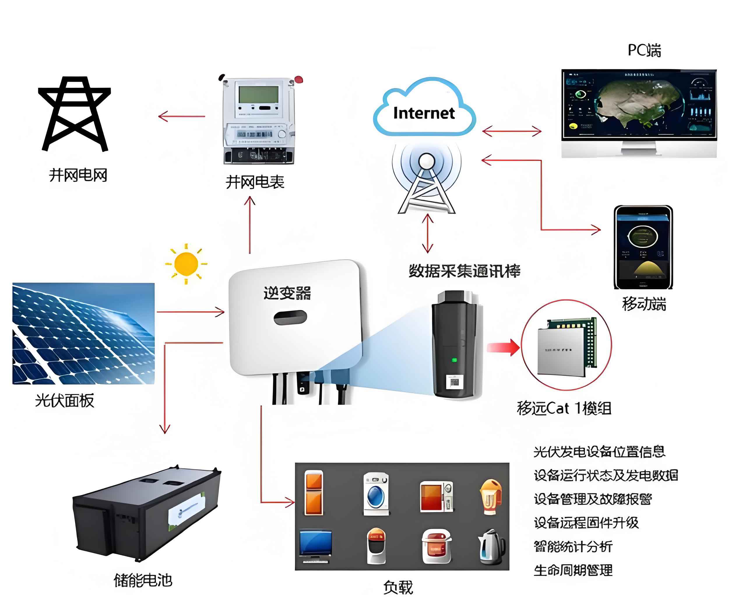
The mechanical structure of the solar-powered cart is fundamental to its functionality. The cart body, constructed from durable materials, features a triangular side profile for stability. The photovoltaic module is mounted at a 37° tilt angle relative to the horizontal plane, optimized for solar capture in northwestern regions. This angle maximizes the efficiency of the solar system by aligning with the local sun path. The cart is equipped with four swivel casters for mobility, allowing the entire solar system to be repositioned as needed. The assembly includes a control system housing that contains the battery, controller, and inverter, ensuring all components of the solar system are protected and accessible. Below is a table summarizing key mechanical parameters:
| Component | Specification | Value |
|---|---|---|
| Photovoltaic Module | Power Rating | 200 W |
| Cart Dimensions | Length × Width × Height | 1640 mm × 990 mm × 900 mm |
| Tilt Angle | Optimized for Region | 37° |
| Weight Capacity | Estimated Load | 50 kg |
| Material | Frame Construction | Steel Alloy |
The electrical design of the solar system is divided into two main subsystems: the illumination control circuit and the photovoltaic power generation system. The illumination device utilizes an AT89C51 microcontroller to manage LED arrays, ensuring low-power operation. The microcontroller circuit operates at 5V, derived from the main 12V solar system bus via a 7805 voltage regulator. The driver circuit employs CAT4104 chips to control current flow to the LEDs, with resistors set according to the required current. For instance, the resistor value for the CAT4104 is calculated using the formula: $$R_{\text{SET}} = \frac{0.1}{I_{\text{LED}}}$$ where \(I_{\text{LED}}\) is the desired LED current in amperes. This precise control allows the solar system to efficiently manage illumination without wasting energy.
The photovoltaic power generation system is a classic off-grid solar system configuration. It includes the solar panel, a charge controller, and an inverter. The controller implements Maximum Power Point Tracking (MPPT) technology to optimize energy harvest from the solar system, achieving up to 97% efficiency. This ensures that the solar system can reliably charge the battery and power the load under varying environmental conditions. The battery storage is a critical component, sized based on the load requirements and autonomy days. The capacity calculation follows the standard formula for independent solar systems:
$$C = \frac{P \times t \times D}{V \times \eta} \times S$$
where \(C\) is the battery capacity in ampere-hours (Ah), \(P\) is the load power in watts (W), \(t\) is the daily usage time in hours (h), \(D\) is the number of autonomy days, \(V\) is the system voltage in volts (V), \(\eta\) is the inverter efficiency (assumed 0.9), and \(S\) is the safety factor (typically 1.6 to 2). For this design, with \(P = 30\, \text{W}\), \(t = 8\, \text{h}\), \(D = 2\), \(V = 12\, \text{V}\), \(\eta = 0.9\), and \(S = 1.6\), the calculation yields:
$$C = \frac{30 \times 8 \times 2}{12 \times 0.9} \times 1.6 = \frac{480}{10.8} \times 1.6 \approx 44.44 \times 1.6 \approx 71.1\, \text{Ah}$$
Thus, a 64 Ah, 12V solar gel battery is selected to meet the needs of the solar system, providing a buffer for practical variations. The following table outlines the electrical specifications:
| Component | Parameter | Value |
|---|---|---|
| Solar Panel | Rated Power | 200 W |
| Battery | Capacity | 64 Ah, 12V |
| Controller | Type | MPPT with Multi-sensor Fusion |
| Inverter | Efficiency | 97% |
| LED Load | Power Consumption | 30 W |
| Microcontroller | Model | AT89C51 |
To validate the performance of the solar system, I conducted simulations using PVsyst 6.0.6 software. The model incorporated local meteorological data, including solar radiation values referenced from NASA databases for the target region. The simulation assessed key metrics such as daily energy generation and battery charge rates over a year. The results indicate that the solar system can effectively meet the illumination load, with an average battery charge rate of 80.6%. However, during months like January and December, there is a risk of load shedding due to lower solar insolation. The table below summarizes the monthly simulation outcomes, highlighting the reliability of the solar system:
| Month | Energy Generated (kWh/day) | Energy Required (kWh/day) | Battery Charge Rate (%) |
|---|---|---|---|
| January | 0.25 | 0.20 | 70.2 |
| February | 0.28 | 0.20 | 75.8 |
| March | 0.32 | 0.20 | 82.4 |
| April | 0.35 | 0.20 | 85.1 |
| May | 0.38 | 0.20 | 88.7 |
| June | 0.40 | 0.20 | 90.5 |
| July | 0.39 | 0.20 | 89.3 |
| August | 0.37 | 0.20 | 86.9 |
| September | 0.34 | 0.20 | 83.6 |
| October | 0.31 | 0.20 | 80.2 |
| November | 0.27 | 0.20 | 73.4 |
| December | 0.24 | 0.20 | 68.9 |
| Annual Average | 0.32 | 0.20 | 80.6 |
The simulation confirms that the solar system design is robust, with only a 5% probability of load loss annually. This performance underscores the viability of using repurposed photovoltaic modules in such a solar system, as the high solar resource in western regions compensates for any degradation in panel efficiency. Moreover, the modular nature of the solar system allows for scalability; multiple units can be interconnected to form a larger solar system array for emergency power applications, enhancing its utility in disaster response scenarios.
In terms of control software, the microcontroller program is written in C language to manage the illumination patterns. The code snippet below demonstrates a simple blinking routine for an LED connected to port P1.0, with a 2-second interval. This program is embedded in the AT89C51, enabling the solar system to automate lighting based on predefined schedules or sensor inputs:
“`c
#include
sbit L1 = P1^0;
void delay2s(void) {
unsigned char i, j, k;
for(i = 20; i > 0; i–)
for(j = 20; j > 0; j–)
for(k = 248; k > 0; k–);
}
void main(void) {
while(1) {
L1 = 0;
delay2s();
L1 = 1;
delay2s();
}
}
“`
This program illustrates how the solar system integrates smart control to conserve energy. The delay function can be adjusted based on real-time conditions, such as ambient light levels detected by sensors, making the solar system more responsive and efficient. The driver circuit for the LEDs further optimizes power usage by regulating current precisely, which is crucial for extending battery life in the solar system.
Another critical aspect of the solar system is the charge controller algorithm. The MPPT technology employs a perturb-and-observe method to continuously adjust the operating point of the photovoltaic module. The power output of the solar panel is given by $$P = V \times I$$, where \(V\) is the voltage and \(I\) is the current. The controller samples these values and increments or decrements the voltage to find the maximum power point, ensuring the solar system extracts the most energy available. This process can be described mathematically: $$\frac{dP}{dV} = 0$$ at the maximum power point. By implementing this in the controller, the solar system maintains high efficiency even under partial shading or temperature variations.
Furthermore, the mechanical design of the solar system cart incorporates considerations for wind resistance and durability. The 37° tilt angle not only optimizes solar capture but also reduces wind load compared to steeper angles. The frame is analyzed using structural mechanics principles to ensure it can withstand typical environmental stresses. The stress distribution can be modeled with equations such as $$\sigma = \frac{F}{A}$$, where \(\sigma\) is the stress, \(F\) is the force, and \(A\) is the cross-sectional area. This ensures the solar system remains stable and operational in diverse conditions.
The battery management within the solar system is also pivotal. The gel battery selected offers deep-cycle capabilities and low maintenance, ideal for remote deployments. The charging process involves three stages: bulk, absorption, and float, controlled by the MPPT controller. The bulk stage charges at constant current until the voltage reaches a set point, followed by constant voltage absorption, and finally a float stage to maintain full charge. This multi-stage approach prolongs battery life, which is essential for the long-term reliability of the solar system.
In addition to the technical design, the economic and environmental benefits of this solar system are significant. By reusing decommissioned photovoltaic modules, the design reduces electronic waste and lowers material costs. The solar system operates with zero emissions, contributing to carbon reduction goals. Its mobility allows it to serve temporary installations, such as construction sites or outdoor events, where grid power may be unavailable. The table below compares this solar system with traditional diesel generators, highlighting its advantages:
| Aspect | Solar System Cart | Diesel Generator |
|---|---|---|
| Fuel Source | Solar Energy (Free) | Diesel (Costly) |
| Emissions | Zero | High CO2 and Pollutants |
| Noise Level | Silent Operation | Loud (>70 dB) |
| Maintenance | Low (Few Moving Parts) | High (Regular Servicing) |
| Mobility | Easy to Move | Heavy and Bulky |
| Lifespan | 20+ Years for Panels | 5-10 Years |
This comparison underscores why the solar system approach is superior for sustainable development. The solar system cart can be deployed in ecologically sensitive areas without disturbing wildlife or polluting the environment. Its illumination function can enhance safety in remote communities, while the independent power supply supports small devices like phones or radios, extending its utility beyond lighting.
Looking ahead, the solar system design can be enhanced with Internet of Things (IoT) capabilities. By adding wireless sensors and connectivity, the solar system could report its status, such as battery level or energy generation, to a central server. This would enable predictive maintenance and optimize deployment strategies. For example, the solar system could automatically adjust its tilt angle based on weather forecasts to maximize energy harvest. Such smart features would make the solar system even more resilient and user-friendly.
In conclusion, this solar system-powered mobile illumination cart represents a practical application of photovoltaic technology. The design integrates mechanical robustness, efficient electrical systems, and intelligent control to create a versatile tool. Through simulations and calculations, I have demonstrated that the solar system can reliably meet energy demands in high-irradiance regions. The use of repurposed components aligns with circular economy principles, reducing waste and cost. As the world transitions to renewable energy, small-scale, adaptable solar systems like this will play a crucial role in providing clean power for diverse needs. Future work could focus on scaling the solar system for larger applications or integrating it with other renewable sources, further advancing the sustainability of energy solutions.