
In recent years, lithium-ion batteries have become integral to modern energy systems, powering electric vehicles, grid storage, and portable electronics. Among various cathode materials, lithium iron phosphate (LiFePO4) batteries are widely adopted due to their inherent thermal stability, long cycle life, and cost-effectiveness. However, safety remains a critical concern, especially under abusive conditions such as external short-circuit (ESC) events. ESC can induce rapid current surges, leading to excessive heat generation, potential thermal runaway, and catastrophic failures. Therefore, understanding the damage characteristics of LiFePO4 batteries under ESC is paramount for designing reliable protection systems. In this study, I investigate the ESC response of cylindrical LiFePO4 batteries, focusing on damage modes, protection mechanisms, and the implications for system-level safety design.
ESC events in battery systems often result from accidental contact between terminals or insulation failures. Traditional protection relies on fuses or circuit breakers, but their response must align with the battery’s intrinsic damage thresholds to prevent over-damage. Prior research has extensively analyzed voltage, current, and temperature profiles during ESC, yet few studies link these responses to fuse protection design. Specifically, the interplay between battery damage boundaries and fuse characteristics remains underexplored. This work aims to bridge that gap by conducting controlled ESC tests on LiFePO4 batteries, identifying key damage boundaries, and proposing guidelines for fuse selection. The findings emphasize that effective protection must consider not only the fuse’s trip time but also the battery’s safety, fusing, and performance degradation limits.
The core of this research is a custom-built ESC test platform capable of generating currents up to 5000 A with time control as low as 0.1 ms. This platform allows precise replication of ESC scenarios at both cell and system levels. By varying current magnitude and duration, I categorize damage into three modes: rupture leakage, internal fusing, and cumulative degradation. Notably, the boundaries for these modes exhibit inverse-time characteristics, meaning that higher currents cause damage in shorter times. A critical finding is the intersection of the safety and fusing boundaries at a current root-mean-square (RMS) value of 30C (where C is the battery’s capacity rate), which delineates regions where either rupture or fusing dominates. Below this point, batteries risk rupture due to prolonged heating; above it, internal fuses activate quickly, enhancing protection reliability. Furthermore, for sub-threshold ESC events, repeated shocks can accumulate damage, eventually leading to failure. These insights underscore the need for multi-level protection strategies in battery packs.
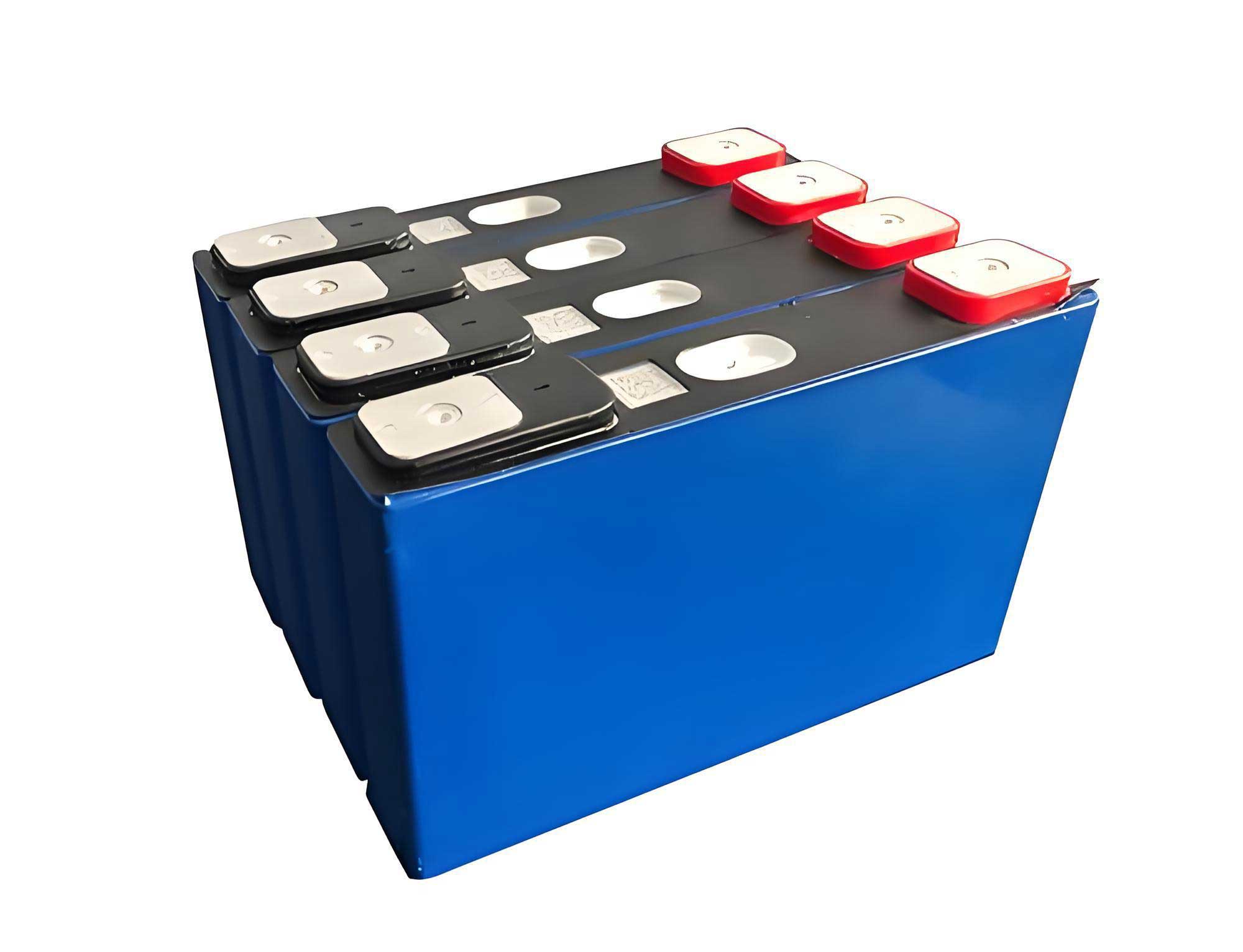
To provide a comprehensive view, I first detail the experimental setup. The LiFePO4 battery used here has a nominal capacity of 20 Ah, an operating voltage range of 2.5–3.65 V, and a cylindrical form factor (34 mm diameter × 184.2 mm height). Importantly, the cell incorporates an internal fusing point at the positive terminal, designed to melt under overcurrent conditions, akin to a fuse. This feature is crucial for studying intrinsic protection mechanisms. The ESC test platform employs a multi-channel topology with MOSFET switches, enabling parallel connections to scale current output. Each channel handles up to 100 A, and by combining channels, I achieve currents from hundreds to thousands of amperes. Time control is implemented via software, allowing pulses from 0.1 ms to several seconds. For system-level simulations, a lithium titanate (LTO) battery module (5 series, 25 Ah) is connected in series with the LiFePO4 cell to elevate the short-circuit voltage, mimicking pack-level faults. All tests begin with batteries at 100% state of charge (SOC), ensured by a standard constant-current-constant-voltage charge protocol.
The experimental matrix encompasses both cell-level and system-level ESC tests, as summarized in Table 1. Cell-level tests involve the LiFePO4 battery alone with varying channel counts (20 to 50 channels), letting the current flow until either rupture or internal fusing occurs. System-level tests combine the LiFePO4 battery with the LTO module, using 50 channels and controlled pulse widths (50 ms, 80 ms, 300 ms, and unrestricted). Repeated ESC tests are performed on cells that survive without fusing or rupture to assess cumulative effects.
| Test ID | Short-Circuit Object | Channels | Duration Control |
|---|---|---|---|
| 1 | LiFePO4 Cell | 20 | Uncontrolled (until event) |
| 2 | LiFePO4 Cell | 30 | Uncontrolled (until event) |
| 3 | LiFePO4 Cell | 40 | Uncontrolled (until event) |
| 4 | LiFePO4 Cell | 50 | Uncontrolled (until event) |
| 5 | LiFePO4 Cell + LTO Module | 50 | 50 ms |
| 6 | LiFePO4 Cell + LTO Module | 50 | 80 ms |
| 7 | LiFePO4 Cell + LTO Module | 50 | 300 ms |
| 8 | LiFePO4 Cell + LTO Module | 50 | Uncontrolled (until event) |
Results from cell-level ESC tests reveal two distinct outcomes. For lower currents (Tests 1 and 2, with channel counts 20 and 30), the LiFePO4 battery undergoes rupture and electrolyte leakage after tens of seconds. The current and voltage profiles show seven phases: rapid current rise, polarization stages, a quasi-steady state, rupture, weak connection, and open circuit. During rupture, internal pressure builds from side reactions like SEI decomposition and electrolyte vaporization, eventually venting through the safety valve. In contrast, at higher currents (Tests 3 and 4, with 40 and 50 channels), the internal fuse melts within seconds, abruptly cutting off the current. Post-test dissection confirms the fused point at the positive tab. Temperature measurements indicate that fusing significantly reduces heat accumulation; for instance, in Test 4, the tab temperature peaks at only 42°C, whereas in Test 1, it exceeds 148°C. This suggests that larger currents, while seemingly more severe, actually trigger faster protection, mitigating thermal damage.
System-level ESC tests yield currents in the range of 2726–2878 A (136–144C), representative of pack-level faults. Controlled-duration tests (50 ms, 80 ms, 300 ms) show that short pulses cause minimal temperature rise on the cell surface, though tab heating is noticeable. Repeated 50 ms ESC pulses (up to 20 times) produce no observable degradation in the LiFePO4 battery, as evidenced by consistent current peaks. However, with 80 ms pulses, the internal fuse melts after the third shock, and with 300 ms pulses, it melts after the second. This demonstrates cumulative damage: sub-threshold ESC events gradually weaken the cell, eventually reaching the fusing boundary. The uncontrolled Test 8 results in fusing at 315.6 ms, aligning with the trend that higher currents shorten the fusing time.
To quantify these observations, I analyze the fusing and safety boundaries mathematically. The fusing time $t_{\text{fuse}}$ relates to the current squared average $ \bar{I^2} $ via a heat balance equation. Assuming negligible heat loss during the short event, the energy required to melt the fuse material is proportional to $ I^2 R t $, where $ R $ is the fuse resistance. Thus, we derive:
$$ t_{\text{fuse}} = \frac{a}{\bar{I^2} – b} $$
where $ a $ and $ b $ are constants dependent on material properties and initial temperature. Fitting experimental data from fusing events (Table 2) confirms this inverse relationship. Similarly, the rupture time $ t_{\text{rupture}} $ for safety boundary follows an inverse-time pattern with current RMS value $ I_{\text{rms}} $.
| Test Level | $ \bar{I^2} $ (A²) | $ t_{\text{fuse}} $ (ms) |
|---|---|---|
| System | 6,133,221.58 | 263.7 |
| System | 5,856,144.56 | 315.6 |
| System | 6,978,546.58 | 219.5 |
| Cell | 810,335.73 | 1368.0 |
| Cell | 812,847.91 | 1520.8 |
| Cell | 819,277.72 | 2353.3 |
| Cell | 555,693.49 | 3855.5 |
By plotting $ t $ versus $ I_{\text{rms}} $ for both fusing and rupture events, I obtain boundary curves. The safety boundary describes the onset of rupture, and the fusing boundary denotes internal fuse activation. Their expressions are:
$$ t_{\text{rupture}} = \frac{1.039 \times 10^7}{I_{\text{rms}}^2 – 3.194 \times 10^4} \quad \text{(seconds)} $$
$$ t_{\text{fuse}} = \frac{8.440 \times 10^5}{I_{\text{rms}}^2 – 3.359 \times 10^5} \quad \text{(seconds)} $$
These curves intersect at $ I_{\text{rms}} = 600 $ A, equivalent to 30C for the 20 Ah LiFePO4 battery. Below this current, rupture tends to occur before fusing, posing a higher safety risk. Above it, fusing predominates, offering quicker protection. Additionally, a third boundary—performance degradation—exists within the safe region, where repeated ESC pulses cause incremental damage that may accumulate over time. This tri-boundary framework is crucial for protection design, as illustrated in Figure 1 (conceptual diagram).
The implications for battery system protection are profound. Relying solely on cell-internal fuses is insufficient, especially at lower short-circuit currents where rupture may happen. System-level fuses must be selected to operate before the battery reaches any damage boundary. Ideally, the fuse characteristic curve should lie below the battery’s safety and fusing boundaries across all possible fault currents. For LiFePO4 batteries, this means considering the 30C intersection point: for currents below 30C, fuses should trip very quickly to prevent rupture; for currents above, they can be slightly slower but must still preempt internal fusing to avoid cell isolation. Moreover, cumulative damage from transient faults necessitates robust monitoring—for example, tracking current spikes and cell impedance to predict degradation.
In practice, designing such protection requires detailed knowledge of the battery’s ESC response. The LiFePO4 battery’s robust chemistry aids safety, but as shown, it is not immune to damage under prolonged low-current shorts. Therefore, fuse ratings should be based on the battery’s time-current characteristics rather than just maximum current. A stepwise approach is recommended: first, characterize the cell’s ESC boundaries through experiments like those described here; second, model the system’s fault current profile, accounting for pack voltage and internal resistance; third, select fuses with inverse-time curves that stay within safe zones. For instance, a fuse with a trip time of 100 ms at 1000 A might protect a LiFePO4 pack, but verification against the degradation boundary is needed to ensure cycle life isn’t compromised.
Beyond fuses, other protective measures can complement ESC mitigation. Active systems like battery management units (BMUs) can detect sudden voltage drops and open contactors, though their response times are typically slower than fuses. Thermal management can dissipate heat from short-circuit events, delaying rupture. However, these are secondary to a well-designed fuse scheme. The key takeaway is that protection must be holistic, considering all damage modes of the LiFePO4 battery.
To conclude, this study elucidates the ESC damage characteristics of LiFePO4 batteries through controlled experiments. Three damage modes—rupture, internal fusing, and cumulative degradation—are identified, each with inverse-time boundaries. The intersection of safety and fusing boundaries at 30C RMS current serves as a critical design parameter: protection systems should ensure operation below this point to prevent rupture risks. For LiFePO4 battery packs, fuse selection must align with these boundaries to avoid over-damage while maintaining reliability. Future work could extend to other battery chemistries and formats, but the principles remain relevant. Ultimately, integrating battery-specific damage thresholds into protection design enhances overall system safety, fostering trust in lithium-ion technologies for energy storage applications.
The LiFePO4 battery continues to be a cornerstone of safe energy storage, and understanding its failure mechanisms under ESC is vital. By marrying experimental insights with protection engineering, we can develop smarter, safer battery systems that withstand real-world faults without compromising performance or longevity.