
The global imperative to mitigate climate change has catalyzed an unprecedented shift towards renewable energy sources. Integrating intermittent resources like wind and solar into the power grid necessitates robust energy storage systems (ESS) to ensure stability, reliability, and efficiency. Among various storage technologies, electrochemical energy storage, primarily based on lithium-ion batteries, has emerged as a frontrunner due to its high energy density, rapid response, and scalability. Within this domain, lithium iron phosphate (LiFePO4 or LFP) batteries have gained significant traction for large-scale stationary storage applications, primarily owing to their superior thermal and chemical stability compared to high-nickel cathode chemistries. This enhanced safety profile is often attributed to the strong P-O covalent bonds in the olivine structure, which provides exceptional thermal resilience and reduces the risk of oxygen release during abuse.
However, the perception of absolute safety is misleading. While LiFePO4 batteries are less prone to catastrophic thermal runaway with open flames under certain conditions, they are not immune to failure. Under conditions of internal short circuit, overcharging, or external thermal abuse, these batteries can still enter a thermal runaway state. The critical distinction lies in the manifestation: a thermally abused LiFePO4 battery typically undergoes violent venting of a large volume of flammable and toxic gases without sustained flaming combustion. This “flameless” thermal runaway presents a unique and potentially severe secondary hazard in confined ESS installations, such as shipping container-based battery energy storage systems (BESS). The rapid accumulation of these gases within the enclosed module or container can create a highly explosive atmosphere, which, if ignited by an electrical arc or hot surface, can lead to devastating vapor cloud explosions.
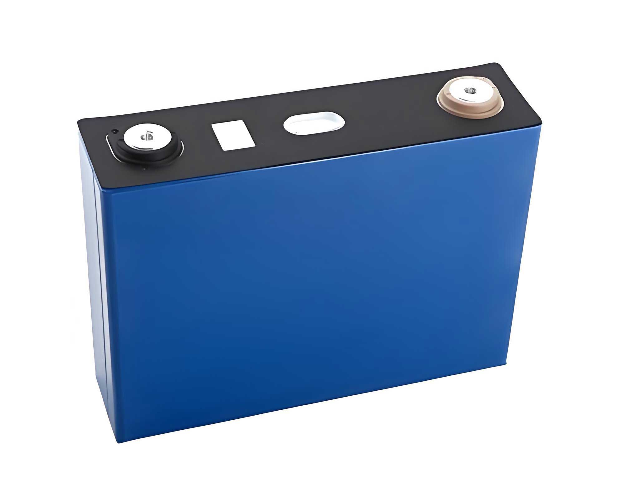
This work presents a two-pronged investigation into the safety of large-format LiFePO4 batteries for grid storage. First, we experimentally characterize the thermal runaway behavior of a commercially relevant 280 Ah LiFePO4 battery cell, quantifying its heat release, mass loss, and gas generation/composition. Second, we translate these empirical findings into a practical risk assessment by modeling the explosion propagation characteristics of the vented gases inside a realistic, 1:1 scale model of a liquid-cooled BESS container using advanced computational fluid dynamics (CFD).
Experimental Characterization of 280 Ah LiFePO4 Battery Thermal Runaway
Methodology and Setup
The test specimen was a prismatic LiFePO4 battery with a nominal capacity of 280 Ah, representative of units deployed in modern megawatt-scale storage projects. Key parameters are summarized in Table 1.
| Parameter | Specification |
|---|---|
| Dimensions (L×W×H) | 174 mm × 72 mm × 204 mm |
| Nominal Capacity | ≥ 280 Ah |
| Nominal Voltage | 3.2 V |
| Cathode Material | LiFePO4 |
| Anode Material | Graphite |
| Mass | 5403.6 ± 2 g |
| State of Charge (SOC) | 100% |
Thermal runaway was triggered via a controlled heating method. The battery, sandwiched with a heating plate and thermal insulation, was placed on a high-precision balance to monitor mass loss in real-time. Seven K-type thermocouples (T1-T7) were attached to the battery surface to track temperature evolution, with T1 on the heated surface center, T2-T4 along the centerline of the opposite face, T5-T6 near the terminals, and T7 on the side. A gas collection hood was positioned above the safety vent. The vented gases were extracted by a pump, directed through a smoothing chamber, and analyzed in real-time using a Fourier Transform Infrared (FTIR) spectrometer and a dedicated hydrogen (H2) sensor. The experimental setup ensured concurrent measurement of temperature, mass, pressure, and gas composition.
Results and Discussion: The Thermal Runaway Process
The thermal runaway process of the large-format LiFePO4 battery, induced by a constant 500 W heat flux, can be demarcated into three distinct phases over approximately 3000 seconds.
Phase I (Heating): From initiation, the battery temperature rose steadily. The heating surface (T1) reached the highest temperature initially, while a gradient developed across the cell thickness. No visible changes or gas release occurred.
Phase II (Vent Opening): At approximately 2037 seconds, the internal pressure exceeded the mechanical limit of the safety vent, causing it to rupture. This was marked by a sharp, audible release and a jet of white aerosol (electrolyte vapor and droplets). A transient positive spike on the mass balance, attributable to the reaction force of the ejected gas, was immediately followed by a steady mass decline. The gas jet was initially rich in electrolyte solvent but relatively low in concentration of other decomposition products. The temperature rise temporarily stalled or slightly decreased due to the cooling effect of the venting process.
Phase III (Full Thermal Runaway): Around 2810 seconds, a second, more violent gas ejection commenced. This event was characterized by an extremely dense white plume consisting of fine solid particulates and a much larger volume of gaseous species. The mass loss rate surged to its maximum, and all battery surface temperatures increased rapidly to their peaks before gradually decaying. The voltage collapsed to zero during this phase. The entire event was “flameless,” consistent with the behavior of LiFePO4 chemistry under thermal abuse.
Quantitative Analysis of Thermal Runaway Signatures
1. Temperature and Mass Dynamics: The temperature profiles for two replicate tests showed excellent consistency. Peak temperatures and their times of occurrence are compared in Table 2. The heated surface reached the highest temperature (~540°C), while the non-heated face and side walls exhibited lower peak temperatures due to thermal inertia and gradients.
| Test | Heated Surface Peak Temp. (°C) | Time to Peak (s) | Non-Heated Face Peak Temp. (°C) | Time to Peak (s) |
|---|---|---|---|---|
| #1 | 551.4 | 3036 | 417.8 | 3087 |
| #2 | 534.4 | 2900 | 422.0 | 2954 |
The mass loss trajectory is a direct indicator of the ejection of volatile components. The total mass loss was approximately 1300 g, representing about 24% of the initial cell mass. The mass loss rate $$ \left( \frac{dm}{dt} \right) $$ evolved from near-zero during heating, to a moderate rate after vent opening, and finally to a maximum rate between -94 to -103 g/s during the intense runaway phase (Phase III). This rapid ejection of material is the primary source for filling a confined space with explosible gas.
2. Gas Composition and Volume: The real-time gas analysis revealed a complex mixture. The major components, quantified by integrating their concentration profiles over the venting period and considering the total gas volume estimated from mass loss, are presented in Figure 1. The composition is dominated by combustible and non-combustible gases.
- Carbon Dioxide (CO2): The highest volume fraction (~44-45%) originates from the decomposition of the carbonate-based electrolyte and possibly reactions involving the cathode and oxide layers.
- Hydrogen (H2): The second major component (~36-39%) is highly flammable. Its primary source is widely attributed to reactions between lithium (intercalated or deposited) and the organic electrolyte or binder (e.g., PVDF).
- Carbon Monoxide (CO): Present at ~6-12%, this toxic and flammable gas results from incomplete decomposition of carbonates and organic solvents.
- Light Hydrocarbons: Species like methane (CH4), ethylene (C2H4), and ethane (C2H6) were detected in smaller amounts, stemming from the cracking and recombination of solvent molecules.
- Other Species: Trace amounts of hydrogen fluoride (HF, from LiPF6 salt and PVDF) and other irritants were also identified, adding to the toxic hazard.
This gas composition is critical for explosion risk assessment. The mixture has a wide flammability range and a significant laminar burning velocity, primarily driven by the high H2 content. The presence of CO2, while non-flammable, affects the mixture’s overall energy density and combustion behavior.
The fundamental energy release during thermal runaway can be conceptually framed by considering the enthalpy change of the internal exothermic reactions. The total heat release $$ Q_{total} $$ driving the temperature rise can be expressed as the sum of the heat generated from individual reactions (SEI decomposition, anode-electrolyte reaction, cathode decomposition, etc.) minus the heat losses:
$$ Q_{total} = \sum_i \Delta H_i \cdot \xi_i – \int hA(T_{cell} – T_{\infty}) dt $$
where $$ \Delta H_i $$ and $$ \xi_i $$ are the enthalpy and extent of reaction *i*, *h* is the heat transfer coefficient, *A* is surface area, and $$ T_{\infty} $$ is ambient temperature. The violent gas ejection is a consequence of the pressure buildup from these reactions: $$ P_{gas} = \frac{nRT_{int}}{V_{void}} $$, where $$ n $$ is the total moles of gas generated, $$ T_{int} $$ is the internal temperature, and $$ V_{void} $$ is the available free volume inside the cell.
Explosion Propagation Modeling in a BESS Container
Computational Model Setup
To translate the single-cell hazard into a system-level risk, we employed the FLACS CFD code, which is validated for vapor cloud explosion (VCE) simulations. A 1:1 geometric model of a standard liquid-cooled BESS container was constructed. The container housed two battery rooms, each containing three racks of battery modules. The key architectural features modeled included:
- Solid walls representing the container structure.
- Doors on the sides of the battery room, modeled as pressure-relief panels with specified opening pressures.
- An inlet vent (lower corner) and an outlet vent (upper corner) for normal ventilation.
- An additional roof-mounted explosion vent panel.
The flammable gas cloud was modeled as a homogeneous mixture of air and the characteristic gas composition derived from the LiFePO4 battery experiments (approx. 37% H2, 45% CO2, 11% CO, 7% hydrocarbons). The mixture was set at a stoichiometric concentration (equivalence ratio Φ = 1) to represent a worst-case, high-energy scenario within a localized pocket of accumulated gas. The cloud was centrally located within one battery room. Ignition was simulated at two different locations: near the floor (“Position 1”) and at mid-height (“Position 2”).
A series of simulations were conducted to investigate the influence of critical design and scenario parameters on the resulting explosion overpressure, which is the key metric for structural damage and human injury. The conditions are summarized in Table 3.
| Case | Door Relief Pressure | Inlet Vent | Ignition Point | Roof Vent |
|---|---|---|---|---|
| A | 10 kPa | Open | Position 1 (Low) | Active (100 kPa) |
| B | 100 kPa | Open | Position 1 (Low) | Active (100 kPa) |
| C | 100 kPa | Open | Position 2 (Mid) | Active (100 kPa) |
| D | 100 kPa | Closed | Position 2 (Mid) | Active (100 kPa) |
| E | 100 kPa | Closed | Position 2 (Mid) | Inactive (10 MPa) |
The governing equations solved by FLACS for compressible, turbulent, reactive flows include the conservation of mass, momentum, energy, and species. For a control volume with porosity (representing obstacles), these can be represented in a general form:
$$ \frac{\partial}{\partial t} (\beta_v \rho \phi) + \nabla \cdot (\beta_j \rho \vec{u} \phi) = \nabla \cdot (\beta_j \Gamma_{\phi} \nabla \phi) + S_{\phi} $$
where $$ \phi $$ represents the solved variable (1 for mass, velocity components for momentum, enthalpy for energy, species mass fraction), $$ \beta_v $$ and $$ \beta_j $$ are volume and area porosities, $$ \rho $$ is density, $$ \vec{u} $$ is velocity vector, $$ \Gamma_{\phi} $$ is the effective diffusivity, and $$ S_{\phi} $$ is the source term (e.g., pressure gradient, gravity, reaction rate).
Simulation Results and Hazard Analysis
1. Overpressure Development and the Role of Venting: The peak overpressure $$ (P_{max}) $$ recorded at monitoring points inside and outside the container is the primary indicator of explosion severity. A critical finding was the profound impact of door relief pressure.
- Case A (Low Door Pressure, 10 kPa): The door acted as an effective early vent. The internal pressure rise triggered door opening before the combustion could fully develop, allowing a significant portion of the unburned gas cloud to be vented out. This resulted in a relatively low internal peak overpressure (~11.7 kPa). The explosion was largely mitigated.
- Case B (High Door Pressure, 100 kPa): With the door sealed longer, the combustion progressed more completely within the confined space, generating higher turbulence and pressure. The peak overpressure more than doubled to ~25 kPa before the door finally opened. This demonstrates that the “strength” of access panels is a crucial design parameter; weaker panels can function as explosion vents, while stronger ones may contain the explosion longer, leading to higher ultimate pressures.
The pressure decay as the blast wave propagates can be analyzed using a scaled decay relationship. We define a simple attenuation ratio *R* between two points: $$ R = \frac{P_1 – P_2}{P_1} $$, where $$ P_1 $$ and $$ P_2 $$ are peak overpressures at the source and a downstream point. Values of *R* increased with distance, highlighting the rapid dissipation of energy in the obstructed environment.
2. Effect of Ignition Location and Obstacles (Case B vs. C): Changing the ignition height from floor level (Case B) to mid-height (Case C) increased the peak overpressure by over 40% (to ~35.8 kPa). The 3D flame propagation visualizations revealed why: ignition at the floor was immediately impeded by the solid boundary, which dampened flame acceleration and directed growth upwards. In contrast, mid-height ignition allowed the flame front to expand radially in all directions with fewer initial obstructions, promoting more rapid coupling with turbulence generated by the battery racks, leading to more violent combustion. This underscores that hazard assessment must consider probable ignition sources, which are often related to electrical equipment that may not be at floor level.
3. Impact of Ventilation and Roof Vents (Cases C, D, E):
- Closed Inlet Vent (Case D): Sealing the normal air inlet altered the flow field and gas mixing prior to ignition. This resulted in a less uniform fuel-air mixture and modified the explosion dynamics, reducing the peak overpressure compared to Case C.
- Inactive Roof Vent (Case E): This was the most severe scenario among those with a closed inlet. Deactivating the dedicated roof explosion vent forced all pressure relief to occur through the structurally stronger side door. The pressure built up for a longer duration and to a higher level (~30 kPa) than in Case D. More critically, the dynamic pressure contours showed a more powerful and directed jet of combustion products escaping through the outlet vent, posing a significant “jet fire” and potential “propagating explosion” threat to adjacent sections or containers.
The function of the roof vent is elegantly described by the venting equation for deflagrations. The required vent area $$ A_v $$ to limit internal pressure to a desired $$ P_{red} $$ is proportional to the enclosure strength and the combustion velocity: $$ A_v \propto \frac{K_{st} \cdot V^{2/3}}{(P_{red})^{1/2}} $$, where $$ K_{st} $$ is the deflagration index of the gas mixture and *V* is enclosure volume. Our simulations validate that a properly sized and positioned vent is essential for safely redirecting the explosion forces and preventing catastrophic overpressurization of the main structure.
Conclusion and Implications for LiFePO4 BESS Safety
This integrated study, combining experimental characterization and high-fidelity explosion modeling, provides critical insights into the safety chain of large-format LiFePO4 battery energy storage systems. The key conclusions are:
- The LiFePO4 Battery Hazard is Gaseous: A 280 Ah LiFePO4 battery undergoing thermal runaway releases a substantial mass (≈1.3 kg) of gas, dominated by H2 (≈37%) and CO2 (≈45%), with significant amounts of CO and light hydrocarbons. This mixture is highly combustive.
- Container Explosion Risk is Real and Modifiable: The vented gases from a single failing LiFePO4 battery can form an explosible cloud within a module or container. The resulting explosion overpressure is not a fixed value but is highly sensitive to design and conditions.
- Venting is Paramount: The pressure at which doors or panels open is a first-order design criterion. Lower opening pressures can prevent dangerous pressure buildup.
- Obstacles and Ignition Source Matter: Internal geometry (racks, cables) influences turbulence and flame acceleration. Ignition location relative to these obstacles significantly affects explosion violence.
- Dedicated Explosion Vents are Crucial: Relying on structural doors for venting is insufficient and can be dangerous. Properly sized and located explosion vents are essential safety devices to safely direct blast forces away and prevent pressure escalation that leads to structural failure or propagating events.
The findings emphasize that the safety of a LiFePO4 BESS cannot be assured by the cell chemistry alone. System-level design focusing on gas management, early detection, targeted ventilation, and robust explosion protection is indispensable. This includes:
- Implementing very early gas detection (H2 sensors) for alarm and pre-ignition ventilation.
- Designing module and container layouts to minimize gas accumulation pockets.
- Specifying low-inertia relief panels on battery modules and container roofs with carefully calculated burst pressures.
- Conducting site-specific explosion hazard analyses using realistic gas compositions from LiFePO4 batteries to inform separation distances and protective measures.
As the deployment of LiFePO4 battery-based energy storage continues to grow exponentially, integrating these safety science principles into codes, standards, and engineering practices is vital for preventing catastrophic incidents and ensuring the sustainable growth of this critical technology for the clean energy transition.