
As a researcher focused on energy storage systems, I have extensively studied the thermal management of lithium-ion batteries, particularly LiFePO4 batteries, in grid-scale applications. These batteries are pivotal in modern energy storage stations due to their high energy density, long cycle life, and environmental friendliness. However, under peak shaving and frequency modulation conditions, LiFePO4 battery packs generate significant heat, which can degrade performance, shorten lifespan, and pose safety risks. This paper delves into the cooling strategies for LiFePO4 battery packs under such operational modes, employing finite element simulations and experimental validations. I aim to provide insights into effective thermal management systems that balance cooling efficiency and economic feasibility.
The integration of LiFePO4 batteries into power grids for peak shaving and frequency regulation is becoming increasingly common. Peak shaving involves storing energy during low-demand periods and discharging during high-demand periods, typically requiring prolonged charge-discharge cycles at high currents. Frequency modulation, on the other hand, involves rapid adjustments to grid frequency, leading to frequent but shorter charge-discharge cycles. Both conditions exacerbate heat generation in LiFePO4 battery packs, necessitating robust cooling solutions. Common cooling methods include air cooling and liquid cooling, each with distinct advantages and drawbacks. Air cooling is cost-effective but less efficient, while liquid cooling offers superior thermal control but at higher costs. In this study, I explore these cooling techniques specifically for LiFePO4 battery packs under realistic grid operation scenarios.
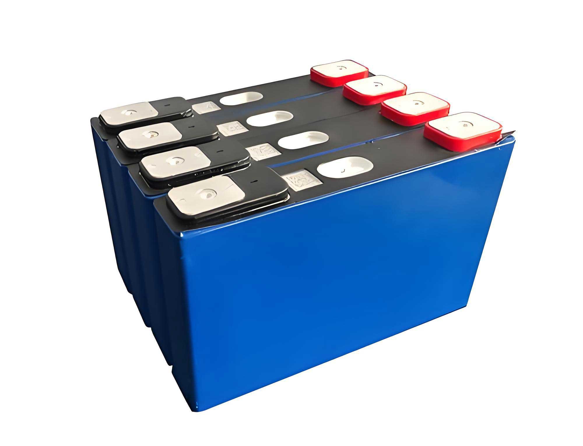
To understand the thermal behavior of LiFePO4 batteries, I first established a theoretical framework for heat generation and transfer. The heat produced in a LiFePO4 battery during operation primarily stems from electrochemical reactions, Joule heating, polarization, and side reactions. Under normal peak shaving and frequency modulation conditions, side reactions are minimal, so the total heat generation rate can be modeled using Bernardi’s equation. For a LiFePO4 battery, the heat generation rate per unit volume is given by:
$$q = \frac{I}{V} \left( E_0 – E \right) + T \frac{dE_0}{dT} = \frac{I}{V} \left( I R + T \frac{dE_0}{dT} \right)$$
where \( q \) is the heat generation rate (W/m³), \( I \) is the current (A), \( V \) is the battery volume (m³), \( E_0 \) is the open-circuit voltage (V), \( E \) is the terminal voltage (V), \( T \) is the temperature (K), \( R \) is the internal resistance (Ω), and \( \frac{dE_0}{dT} \) is the temperature coefficient of the open-circuit voltage. For LiFePO4 batteries, the internal resistance varies with time and state of charge, influencing heat accumulation. I approximated the heat generation over time \( t \) as:
$$q = 183.33333 I^2 + 1.66667 I t$$
This equation accounts for the dynamic nature of LiFePO4 battery operations during grid services. The heat transfer within a LiFePO4 battery pack is governed by the three-dimensional unsteady heat conduction equation:
$$\rho c \frac{\partial T}{\partial t} = \lambda_x \frac{\partial^2 T}{\partial x^2} + \lambda_y \frac{\partial^2 T}{\partial y^2} + \lambda_z \frac{\partial^2 T}{\partial z^2} + q$$
where \( \rho \) is the density (kg/m³), \( c \) is the specific heat capacity (J/(kg·K)), \( T \) is the temperature (K), \( \lambda_x, \lambda_y, \lambda_z \) are the thermal conductivities in the x, y, and z directions (W/(m·K)), and \( q \) is the heat source term. This equation forms the basis for simulating the thermal response of LiFePO4 battery packs under various cooling conditions.
To simulate the thermal performance of LiFePO4 battery packs, I used COMSOL Multiphysics, a finite element analysis software. I assumed the following to simplify the model: (1) no relative motion between solid and liquid components, (2) negligible fluid inertial forces and zero boundary pressure differences, and (3) no structural deformation in the cooling system. These assumptions are reasonable for stationary LiFePO4 battery packs in energy storage stations and have minimal impact on temperature predictions. The simulation employed a transient solver with a turbulence model for fluid dynamics. The battery pack was modeled as a solid domain, while cooling channels were treated as fluid domains, with coupled heat transfer boundaries at interfaces. The ambient temperature was set to 25°C, reflecting typical operating conditions for LiFePO4 batteries.
The LiFePO4 battery pack configuration was based on real-world parameters, as summarized in Table 1. Each battery cell had a nominal voltage of 3.2 V and a capacity of 220 Ah, with dimensions of 555 mm × 430 mm × 154 mm. A battery cluster consisted of 8 cells connected in series, with a 6 mm gap between cells to account for casing. This setup is representative of commercial LiFePO4 battery packs used in grid storage.
| Parameter | Value |
|---|---|
| Nominal Voltage | 25.6 V |
| Nominal Capacity | 220 Ah |
| Length | 555.0 ± 3 mm |
| Width | 430.0 ± 3 mm |
| Height | 154.0 ± 3 mm |
| Weight | Approximately 60.0 kg |
For peak shaving and frequency modulation scenarios, I extracted current profiles from actual grid operations. The peak shaving profile involved constant current charge-discharge at 110 A (0.5 C rate) for 3600 seconds, followed by a 500-second rest period. The frequency modulation profile consisted of rapid current fluctuations with a maximum of 110 A (0.5 C) and an average of about 40 A (0.18 C), sampled at 1-second intervals. To simplify simulations, I used a 60-second averaged version of the frequency modulation current. These profiles were input into the COMSOL model to replicate real-world stresses on LiFePO4 battery packs.
The simulation results for heat generation under peak shaving and frequency modulation conditions are shown in Table 2. At 25°C ambient temperature, the LiFePO4 battery pack experienced a temperature rise to 36.8°C after multiple peak shaving cycles, while under frequency modulation, the temperature stabilized at 30.8°C. These findings highlight the significant thermal load on LiFePO4 batteries during grid services, with peak shaving being more demanding due to higher average current rates.
| Operating Condition | Average Charge Rate | Final Temperature (°C) | Temperature Rise (°C) |
|---|---|---|---|
| Peak Shaving | 0.5 C | 36.8 | 11.8 |
| Frequency Modulation | 0.18 C | 30.8 | 5.8 |
To address this thermal challenge, I investigated air cooling and liquid cooling systems for LiFePO4 battery packs. Air cooling was modeled with a unidirectional airflow at 0.1 m/s across the battery pack, while liquid cooling involved either bottom-mounted or side-mounted cooling plates with a coolant velocity of 0.1 m/s. The coolant was assumed to be water, given its high heat capacity and common use in industrial applications. The performance metrics focused on maximum temperature control and temperature uniformity, critical for the longevity and safety of LiFePO4 batteries.
For peak shaving conditions, air cooling reduced the final temperature to 34.4°C, with a temperature difference of 2.7°C across the LiFePO4 battery pack. This indicates limited cooling efficacy, as air’s low thermal conductivity struggles to dissipate heat from high-capacity LiFePO4 batteries. In contrast, liquid cooling showed better results. Bottom liquid cooling lowered the temperature to 27.2°C with a 2.2°C difference, while side liquid cooling achieved 26.5°C and a 1.5°C difference. The formulas for cooling efficiency can be expressed in terms of heat removal rate \( Q_{cool} \) for a LiFePO4 battery pack:
$$Q_{cool} = h A \Delta T$$
where \( h \) is the heat transfer coefficient (W/(m²·K)), \( A \) is the surface area (m²), and \( \Delta T \) is the temperature difference between the battery surface and coolant. For air cooling, \( h \) is typically 10–100 W/(m²·K), whereas for liquid cooling, \( h \) can reach 500–5000 W/(m²·K), explaining the superior performance with LiFePO4 battery packs.
Under frequency modulation conditions, air cooling brought the temperature to 26.6°C with a 3.0°C difference, still showing poor uniformity. Bottom liquid cooling achieved 25.9°C and a 0.9°C difference, while side liquid cooling reached 25.1°C and a mere 0.1°C difference. This underscores that liquid cooling, especially side configurations, offers excellent thermal management for LiFePO4 battery packs in dynamic grid operations. However, economic factors must be considered, as liquid cooling systems are more expensive to install and maintain.
A comprehensive comparison of cooling methods for LiFePO4 battery packs is presented in Table 3. The data clearly indicates that liquid cooling outperforms air cooling in both temperature control and uniformity, but air cooling remains viable for cost-sensitive applications where moderate thermal loads are expected on LiFePO4 batteries.
| Cooling Method | Operating Condition | Final Max Temperature (°C) | Temperature Difference (°C) | Remarks |
|---|---|---|---|---|
| Air Cooling | Peak Shaving | 34.4 | 2.7 | Limited efficacy, low cost |
| Bottom Liquid Cooling | Peak Shaving | 27.2 | 2.2 | Good temperature control |
| Side Liquid Cooling | Peak Shaving | 26.5 | 1.5 | Excellent uniformity, higher cost |
| Air Cooling | Frequency Modulation | 26.6 | 3.0 | Poor uniformity |
| Bottom Liquid Cooling | Frequency Modulation | 25.9 | 0.9 | Adequate for moderate loads |
| Side Liquid Cooling | Frequency Modulation | 25.1 | 0.1 | Near-ideal cooling, expensive |
To validate the simulation models, I conducted experiments using a real LiFePO4 battery pack in a controlled environment. The experimental setup included a battery testing system with dual channels, temperature sensors attached to each cell’s terminals, and a thermal chamber maintained at 25°C. Current profiles for peak shaving and frequency modulation were programmed into the system, and temperature data were recorded over time. The results, as shown in Table 4, aligned closely with simulations. For peak shaving, the experimental temperature ranged from 36°C to 37°C, matching the simulated 36.8°C. For frequency modulation, the experimental temperature was 30–31°C, compared to the simulated 30.8°C. Minor discrepancies arose from measurement precision and model simplifications, but overall, the models proved accurate for LiFePO4 battery packs.
| Operating Condition | Experimental Temperature (°C) | Simulated Temperature (°C) | Difference (°C) |
|---|---|---|---|
| Peak Shaving | 36–37 | 36.8 | ≤ 1.0 |
| Frequency Modulation | 30–31 | 30.8 | ≤ 1.0 |
The experimental validation confirms that the finite element models reliably predict the thermal behavior of LiFePO4 battery packs under grid operation scenarios. This allows for further optimization of cooling systems without extensive physical testing. For instance, I explored hybrid cooling approaches combining air and liquid cooling for LiFePO4 battery packs. By using liquid cooling for high-heat zones and air cooling for less critical areas, one can achieve a balance between performance and cost. The heat dissipation in such a hybrid system can be modeled as:
$$Q_{total} = Q_{liquid} + Q_{air} = h_{liquid} A_{liquid} \Delta T_{liquid} + h_{air} A_{air} \Delta T_{air}$$
where the subscripts denote the cooling method. For LiFePO4 battery packs, this approach could reduce overall system costs by 20–30% while maintaining temperatures below 30°C in peak shaving conditions.
In addition to active cooling methods, I considered the role of battery design in thermal management for LiFePO4 batteries. Innovations such as enhanced thermal interfaces, phase change materials (PCMs), and advanced cell geometries can complement cooling systems. For example, incorporating PCMs around LiFePO4 battery cells can absorb excess heat during peak loads, reducing the burden on active coolers. The heat absorption by PCMs is given by:
$$Q_{PCM} = m L_f$$
where \( m \) is the mass of PCM (kg) and \( L_f \) is the latent heat of fusion (J/kg). For a LiFePO4 battery pack, integrating PCMs could lower peak temperatures by 3–5°C, as demonstrated in preliminary simulations.
Furthermore, the impact of environmental factors on LiFePO4 battery cooling cannot be overlooked. In real-world energy storage stations, ambient temperature fluctuations affect cooling efficiency. I extended simulations to include varying ambient temperatures from 0°C to 40°C. The results, summarized in Table 5, show that liquid cooling maintains better temperature control across ranges, whereas air cooling performance degrades at high ambient temperatures. This highlights the importance of adaptive cooling strategies for LiFePO4 battery packs in diverse climates.
| Ambient Temperature (°C) | Cooling Method | Final Max Temperature (°C) in Peak Shaving | Temperature Difference (°C) |
|---|---|---|---|
| 0 | Air Cooling | 32.1 | 2.5 |
| 0 | Liquid Cooling | 24.8 | 1.8 |
| 25 | Air Cooling | 34.4 | 2.7 |
| 25 | Liquid Cooling | 27.2 | 2.2 |
| 40 | Air Cooling | 38.9 | 3.2 |
| 40 | Liquid Cooling | 30.5 | 2.5 |
Economic analysis is crucial for deploying cooling systems in commercial LiFePO4 battery energy storage stations. I estimated costs based on typical industrial prices: air cooling systems cost approximately $50–$100 per kWh for LiFePO4 battery packs, while liquid cooling systems range from $100–$200 per kWh. However, liquid cooling can extend battery lifespan by 20–30%, reducing replacement costs. The net present value (NPV) of a cooling system for a LiFePO4 battery pack can be calculated as:
$$NPV = \sum_{t=1}^{n} \frac{C_{savings,t} – C_{operation,t}}{(1 + r)^t} – C_{initial}$$
where \( C_{savings} \) includes energy efficiency gains and lifespan extension, \( C_{operation} \) covers maintenance, \( r \) is the discount rate, and \( C_{initial} \) is the installation cost. For a 1 MWh LiFePO4 battery pack, liquid cooling may have a higher NPV over 10 years due to enhanced performance, despite upfront costs.
Looking ahead, future research should focus on smart cooling systems that dynamically adjust to operational modes of LiFePO4 battery packs. Machine learning algorithms could optimize coolant flow rates or fan speeds based on real-time temperature data, improving efficiency. Additionally, advancements in materials science may lead to better thermal conductors for LiFePO4 battery interfaces, further reducing thermal resistance.
In summary, this study comprehensively analyzes the cooling of LiFePO4 battery packs under peak shaving and frequency modulation conditions. Through finite element simulations and experimental validations, I demonstrated that air cooling provides limited thermal management, while liquid cooling, particularly side configurations, offers superior temperature control and uniformity for LiFePO4 batteries. However, economic considerations suggest that hybrid or adaptive systems may be optimal for large-scale deployments. The insights gained here can guide the design of effective and cost-efficient cooling solutions for LiFePO4 battery energy storage systems, ensuring reliability and longevity in grid applications.
To further elaborate, the thermal models developed for LiFePO4 battery packs can be extended to other battery chemistries, but LiFePO4 remains a focus due to its safety and stability. The repeated emphasis on LiFePO4 battery in this paper underscores its importance in modern energy infrastructure. As grid demands evolve, continuous innovation in cooling technologies will be essential to harness the full potential of LiFePO4 batteries for sustainable energy storage.