
As a piece of electrical equipment, batteries offer advantages such as high energy density, long cycle life, rapid response speed, and minimal environmental pollution. They have found widespread application in daily appliances, transportation, and notably, in power energy storage. Among the various configurations, the prefabricated compartment-style lifepo4 battery is commonly employed in energy storage systems. However, under extreme operating conditions, these lifepo4 battery units can experience thermal runaway. Within a confined space, a fire originating in a single battery energy storage unit has the potential to trigger cascading fires or even explosions in adjacent units. Such incidents present a significant fire load, high risk, and pose considerable challenges for firefighting efforts. The safety and protection issues surrounding lithium-ion battery energy storage power stations are therefore of paramount importance and cannot be overlooked.
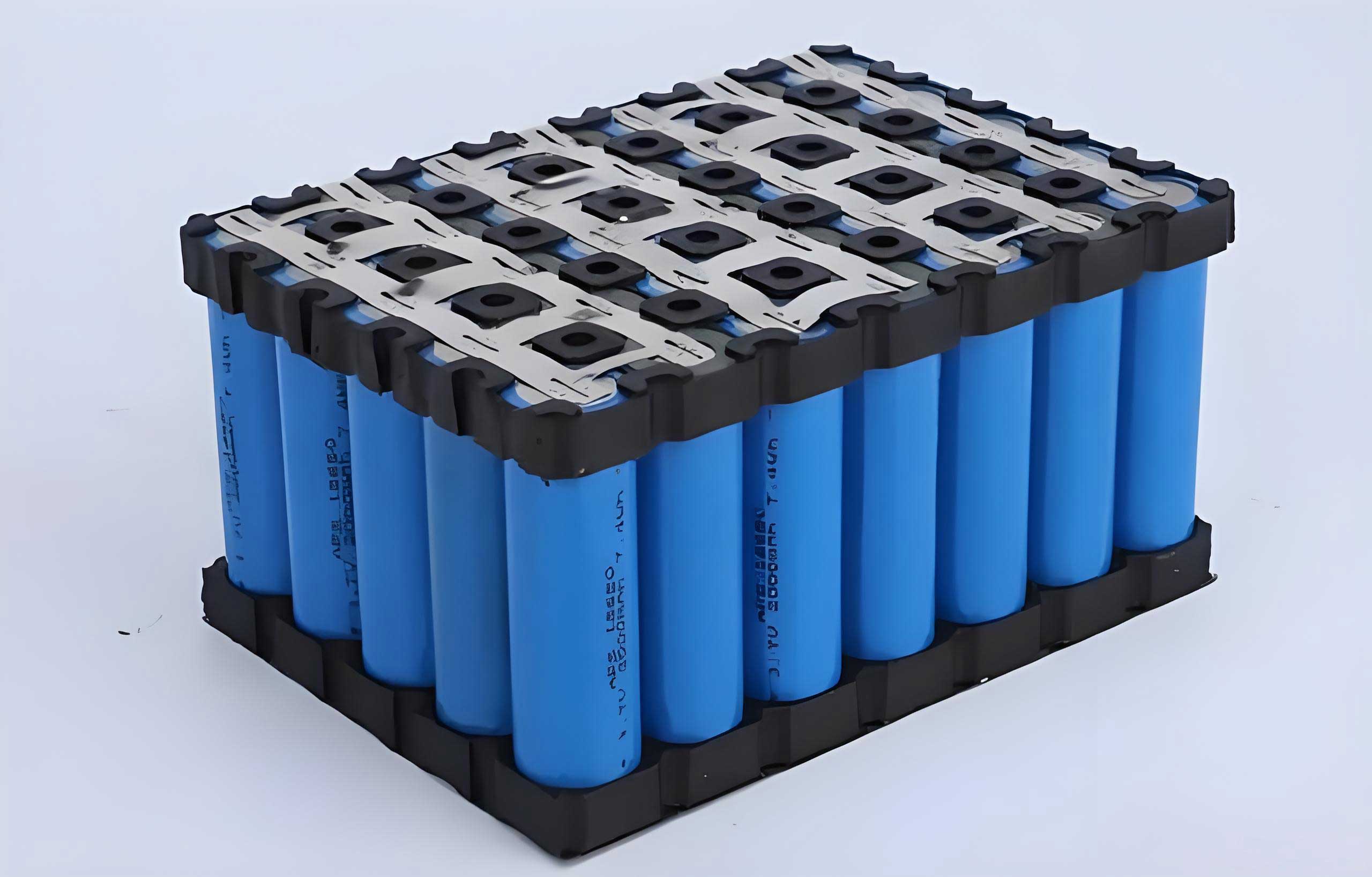
Current research on lithium battery safety is extensive. Studies have investigated the explosive hazards of thermal runaway gases from lifepo4 battery, the influence of state-of-charge (SOC) on explosion risk in confined spaces, and the modeling of explosion characteristics like flammability limits and overpressure. Research has also been conducted on the explosion intensity from overcharging and the equivalent TNT yield. However, these studies often do not address explosion accidents within the context of large-scale, real-world application scenarios for energy storage stations. Given the difficulty of conducting full-scale experimental studies on power station explosions, computer simulation emerges as a viable and practical research methodology.
This study addresses this gap by developing a simulation based on an actual grid-side energy storage power station in operation. Using the FLACS software, a 1:1 scale geometric model was constructed to simulate a real-world scenario. The fuel for the explosion is defined as the vaporized electrolyte from a lifepo4 battery triggered by overcharging. The simulation analyzes the entire process of ignition and explosion within a storage compartment, examining the diffusion characteristics of the blast and its impact on surrounding compartments through data such as burning rate, overpressure, and temperature. Furthermore, the study proposes and validates the effectiveness of installing external safety barriers as a protective measure to mitigate explosion propagation. The findings aim to provide theoretical and data-driven support for the safety design and explosion protection of future electrochemical energy storage stations utilizing lifepo4 battery technology.
Mathematical and Physical Model of the Energy Storage Power Station
Mathematical Foundation
The simulation is performed using FLACS, a computational fluid dynamics (CFD) software developed by GEXCON AS for 3D explosion and dispersion modeling. It is well-suited for risk assessment in both offshore and onshore installations. The software employs the SIMPLE algorithm, solving a set of conservation equations for mass, momentum, energy, and species, coupled with boundary conditions, to compute variables like overpressure, combustion products, flame speed, and fuel consumption rate within the computational domain. The influence of turbulence and chemical reactions are integral to these equations. The general transport equation solved is:
$$
\frac{\partial(\rho \phi)}{\partial t} + \frac{\partial}{\partial x_j}(\rho u_j \phi) = \frac{\partial}{\partial x_j}\left(\Gamma_\phi \frac{\partial \phi}{\partial x_j}\right) + S_\phi
$$
where \(\phi\) represents a general variable (mass, momentum, energy, etc.), \(\rho\) is the gas density, \(x_j\) is the spatial coordinate, \(u_j\) is the velocity vector, \(\Gamma_\phi\) is the diffusion coefficient, and \(S_\phi\) is the source term. This approach accounts for the interaction between the flame and obstacles like equipment and piping, allowing for direct calculation of gas explosion shock waves.
Within the FLACS explosion module, an explosion is initiated by an ignition source igniting a local pocket of flammable gas. The resulting flame propagates through the premixed gas cloud, causing rapid, large-scale combustion—a process whose defining feature is the presence of a shock wave. As the flame propagates, it generates combustion products (e.g., CO₂, H₂O), releases heat, and causes the products to expand. If this expansion cannot be relieved quickly enough, an explosion occurs.
Physical Geometry and Layout
A 1:1 scale physical model of the energy storage power station was constructed for the simulation, as shown in Figure 1. The station covers an area of 0.38 hectares, with dimensions of 93 m (East-West, X-axis), 41 m (North-South, Y-axis), and a height of 2.8 m (Z-axis). The computational domain was extended to 105 m × 50 m × 10 m. The main electrical equipment consists of 16 units of 2 MWh lifepo4 battery storage containers, 16 PCS prefabricated cabins, 2 units of 10 kV busbar cabins, and other auxiliary devices.
The internal structure of a single storage compartment is illustrated in Figure 1(c). Battery racks and modules are arranged symmetrically on both sides of a central 0.8 m wide aisle. Each side contains 7 layers and 16 columns of battery modules, with individual module dimensions of 0.6 m × 0.42 m × 0.24 m.
The pressure relief panel configuration is shown in Figure 1(d). Each storage compartment is equipped with 4 relief panels. Panels P1 and P3 are located on the front and rear doors, respectively, with dimensions of 1 m × 2 m and a critical overpressure of 3 kPa. Panels P5 and P6 are situated on the upper-middle sections of the compartment’s sides, measuring 1.6 m × 0.6 m with a critical overpressure of 20 kPa. Additional monitoring panels (P2, P4, P7) are placed on adjacent compartments (2, 3, 4) to observe the impact from the explosion in Compartment 1. All relief panels are modeled as bi-directional (breakable from either side), with pressure monitoring points at their centers.
Explosion Parameter Configuration
The explosive potential primarily depends on the composition, size, and concentration of the flammable cloud. During thermal runaway of a lifepo4 battery, the combustible components are mainly vaporized organic solvents from the electrolyte, such as propylene carbonate (C₄H₆O₃), ethylene carbonate (C₃H₄O₃), and diethyl carbonate (C₅H₁₀O₃). These solvents have low vapor pressure and are flammable. Following thermal runaway, the vaporized solvents fill the compartment. Upon reaching a critical concentration and being ignited, a deflagration or explosion occurs. As these specific gases are not in the FLACS database, an equivalent mixture based on the stoichiometric combustion equations is used: a blend of 19% CH₄, 56% CO, and 25% H₂.
$$ \text{C}_4\text{H}_6\text{O}_3 \rightarrow \text{CH}_4 + 3\text{CO} + \text{H}_2 $$
$$ \text{C}_3\text{H}_4\text{O}_3 \rightarrow 3\text{CO} + 2\text{H}_2 $$
$$ \text{C}_5\text{H}_{10}\text{O}_3 \rightarrow 2\text{CH}_4 + 3\text{CO} + \text{H}_2 $$
It is assumed that the flammable gas is uniformly distributed within the compartment prior to ignition. The total fuel mass is calculated based on the capacity of a single lifepo4 battery module, simulating a worst-case scenario. To ensure complete combustion, the equivalence ratio of the gas mixture is set to 0.8 (fuel-rich). The ignition point is set at coordinates (X=37.8 m, Y=32 m, Z=0.5 m) inside Compartment 1, with zero delay. The initial conditions for the simulation are summarized in Table 1.
| Parameter | Value |
|---|---|
| Ambient Temperature | 20 °C |
| Ambient Pressure | 101.325 kPa (Atmospheric) |
| Wind Speed | 0 m/s |
| Boundary Condition | EULER Equation |
| Turbulence Model | Standard k-ε Model |
| Air Composition | 20.95% O₂ + 79.05% N₂ |
Simulation and Analysis of Explosion Propagation in Prefabricated Compartments
Comparative Analysis of Explosions in Different Zones
Actual explosion accidents often stem from a single cell fire leading to a chain reaction. Without timely intervention, this can escalate to a full compartment explosion. Therefore, for a compartment with a fixed battery array, the total fuel mass is constant. Due to the limitation in FLACS where fuel must be defined as a “gas cloud,” three simulation cases were designed to study the effect of different initial gas cloud locations:
Case 1 (Baseline): Explosion initiated in the geometric center of the compartment.
Case 2: Explosion initiated in the left half of the compartment (same fuel mass, distributed volume).
Case 3: Explosion initiated in the left half with the fuel mass concentrated in a smaller volume (higher concentration, same total mass).
The comparative results are presented in Table 2. Key observations are:
- In Case 2, changing the ignition location caused the front/rear door relief panels (P1/P3) to open earlier. However, the side panel (P5), being farther from the ignition point, opened later. This increased the overall explosion duration and severity, resulting in higher overpressure shocks compared to the central ignition baseline.
- In Case 3, concentrating the fuel in a smaller volume created a locally oxygen-deficient region at the ignition point. This led to a delayed and less violent ignition, with significantly reduced explosion strength. This scenario is less representative of a typical full-compartment fuel distribution.
Comparing the three cases leads to the conclusion: The location of the ignition point relative to the relief panels influences the explosion strength. However, if the local fuel concentration becomes too high, leading to oxygen starvation, the explosion intensity can be greatly diminished. For a detailed study of the impact on adjacent compartments, the baseline central ignition scenario (Case 1) is analyzed in depth.
| Case | Peak Burning Rate (kg·m⁻³·s⁻¹) | P1 Opening Time (s) | P5 Opening Time (s) | P2 Peak Overpressure (kPa) | P4 Peak Overpressure (kPa) | P7 Peak Overpressure (kPa) |
|---|---|---|---|---|---|---|
| Case 1 | 90.4 | 0.48 | 0.46 | 23 | 15 | 5 |
| Case 2 | 206 | 0.38 | 0.44 | 34.5 | 24.9 | 9.3 |
| Case 3 | 19.8 | 1.48 | 1.61 | 0.8 | 6.7 | 1.9 |
Detailed Analysis of Central Zone Explosion (Case 1)
The following analysis uses the ignition time as t = 0 s.
Burning Rate 3D Analysis
The progression of the flame, represented by the burning rate, is shown in Figure 2. Initially, the explosion propagates rapidly from the ignition point, with a peak local burning rate of 90.4 kg/(m³·s). At approximately t = 0.48 s, the front and rear door relief panels (P1, P3) are breached, allowing flames to vent outward. The flames primarily propagate along the X-axis (longitudinal direction of the compartment array), developing a cylindrical shape. By t = 0.56 s, flames have reached Compartment 3, posing a risk of secondary ignition. Flame fronts also impact Compartment 2. After t = 0.7 s, the flames are largely confined within the originating compartment as the combustion subsides. Figure 3 shows the burning rate at the center of key relief panels, confirming P1/P3 opening at ~0.49 s and P5 at ~0.46 s.
Temperature Distribution Analysis
The temperature distribution, shown in Figure 4, provides further insight. At t = 0.46 s, the compartment is filled with high-temperature gases, with a peak exceeding 2,200 K. Upon panel failure, high-temperature gases are ejected. The high-temperature zone completely envelops the source compartment and spreads hemispherically. Ejected hot gases from the door panels create distinct plumes. The thermal effects from a single compartment lifepo4 battery explosion cover a vast area of the entire station, even without secondary explosions, posing a significant radiant heat hazard. Similar to the flames, the high-temperature zone spreads predominantly along the Y-axis (lateral direction across compartments).
Overpressure Analysis on Adjacent Compartments
The overpressure on relief panels of adjacent compartments indicates the blast loading they experience. Figure 5(a) shows overpressure on panels of the source compartment (Compartment 1). The side panels (P5, P6) with lower critical pressure fail first (~0.47 s), followed by the door panels. Figure 5(b) shows the overpressure on panels of adjacent compartments. Panel P4 (on Compartment 3, closest laterally) experiences the earliest and highest peak overpressure (15 kPa), well above its 3 kPa critical value. After the shockwave passes, a negative pressure phase occurs. Panels P2 (Compartment 2) and P7 (Compartment 4) peak around t = 0.51 s at 23 kPa and 5 kPa, respectively, both exceeding their critical pressures. Combined with the observed flame and high-temperature impingement (Figures 2 & 4), it is concluded that panels P2, P4, and P7 would be breached, allowing flames and hot gases to enter adjacent compartments containing other lifepo4 battery units, creating a high risk of cascading explosions.
Key findings from the baseline explosion simulation are:
- The explosion within the lifepo4 battery compartment is violent. Flames and high-pressure gases breach relief panels within ~0.5 s, forming a cylindrical fireball outside. Ejection from the larger door panels is more severe.
- With ample oxygen outside, the fire intensifies and spreads to surrounding compartments within 1 second. The thermal radiation effect covers the entire station.
- Flame and high-temperature spread is predominantly lateral (Y-axis) across the row of compartments.
- The overpressure from the initial explosion is sufficient to blow open relief panels on adjacent compartments from the outside, creating a direct pathway for flames and posing a severe risk of domino explosions.
Simulation and Comparison of Explosion Process with Protective Isolation Measures
Given the significant hazard of lateral flame propagation and the risk of cascading explosions, this study proposes installing vertical barrier walls (isolation plates) around the compartment where the initial explosion occurs. The goal is to deflect the venting flames upward rather than allowing horizontal spread. The feasibility is analyzed via simulation, using the Case 1 explosion scenario. The modified model with barrier installation is shown in Figure 6.
Influence of Barrier Distance from Compartment
To determine an effective installation distance, three simulations were conducted with barrier heights fixed at 1.8 m and distances of 0.25 m, 0.5 m, and 0.75 m from the compartment wall. The overpressure on adjacent compartment relief panels was compared (Figure 7).
Analysis shows that a distance of 0.25 m is too close. The overpressure on Panel P2 (Compartment 2) remains very high (23.8 kPa), indicating limited barrier effect. Distances of 0.5 m and 0.75 m yield similar and much lower overpressures on P2 (~5 kPa). However, for panels P4 and P7 on the laterally adjacent compartments, the overpressure reduction is less pronounced, and peaks still exceed the 3 kPa critical value. This is attributed to the 1.8 m barrier height being level with the bottom of the side relief panels (P5/P6), offering limited obstruction to the shockwave and flames venting from those points. Based on this, a 0.5 m distance is selected as optimal for further study on barrier height effectiveness.
Analysis and Comparison of Different Barrier Heights
Two simulations are compared: Barrier height = 1.8 m (level with side vents) and Barrier height = 2.8 m (equal to compartment roof height). Distance is fixed at 0.5 m.
Explosion Burning Rate Comparison
The flame development with a 1.8 m barrier is shown in Figure 8. Initially confined, flames vent from side panels at t=0.46 s. The barrier provides noticeable blocking in the X-direction towards Compartment 2 but limited obstruction in the Y-direction towards Compartment 4 due to its height. By t=0.6 s, flames are largely contained within the barrier enclosure. Figure 9 shows the result with a 2.8 m high barrier. The improvement is dramatic. The barrier completely redirects the venting flames from side panels upward. Flames never propagate horizontally to reach adjacent compartments, significantly enhancing safety.
Overpressure on Adjacent Compartments
Figure 10 shows the overpressure on adjacent compartment panels. With a 1.8 m barrier, the peak overpressure on P2 drops to 5 kPa (from 23 kPa without barrier), falling below its critical value. This greatly improves safety for the compartment directly in front. However, overpressure on P4 and P7, while reduced, remains at levels (6 kPa, 5 kPa) that could still breach their 3 kPa panels. With the 2.8 m barrier (Figure 10b), the overpressure on P2 further decreases to 4 kPa. The arrival time of the peak pressure is slightly delayed, indicating better blocking. The effect on P4 and P7 is similar to the 1.8 m case, likely due to their proximity to the blast source.
Synthesizing the results on protective measures:
- Installing isolation barriers around the exploding lifepo4 battery compartment effectively suppresses horizontal flame spread, forcing venting gases upward and drastically reducing the risk of domino explosions.
- The barrier installation distance should not be too small (e.g., 0.25 m) as it diminishes the protective effect.
- A barrier height equal to the side vent height (1.8 m) offers good protection in the forward/rear direction but limited protection against laterally venting flames from side panels.
- Increasing the barrier height to the full compartment roof height (2.8 m) provides comprehensive protection by enclosing all vent points, nearly eliminating the risk of horizontal flame propagation to adjacent compartments.
- Even with barriers, the overpressure on the side relief panels of immediately adjacent compartments, while reduced, may still exceed their low critical opening pressure (3 kPa). Enhancing the structural strength (critical pressure) of these side relief panels is recommended as a complementary measure.
Conclusion
This study conducted a detailed simulation of an explosion accident in a prefabricated compartment-style energy storage power station utilizing lifepo4 battery technology. A 1:1 scale model was developed, and the explosion process, along with protective measures, was analyzed. The key conclusions are as follows:
- Following an ignition event within a lifepo4 battery compartment, the reaction is extremely violent. Generated flames and overpressure breach relief panels within approximately 0.5 seconds, forming a cylindrical fireball that propagates laterally. The larger door panels are the primary vent paths, leading to more severe external flames. The blast wave and thermal effects rapidly impact adjacent compartments. Crucially, the overpressure is sufficient to blow open the relief panels of neighboring compartments from the outside, creating direct pathways for flame ingress and presenting a high risk of cascading explosions.
- Implementing vertical safety barrier walls around the compartment where the initial lifepo4 battery explosion occurs is a highly effective mitigation strategy. These barriers dramatically inhibit horizontal flame diffusion, forcing combustion products to vent upwards. The flame’s main propagation direction is successfully altered from horizontal to vertical, significantly enhancing the safety of adjacent compartments. The installation distance of these barriers is important; placing them too close to the compartment wall reduces their effectiveness.
- The height of the isolation barrier is a critical design parameter. A barrier height level with the side vent openings (1.8 m) provides substantial protection in the longitudinal direction (along the compartment row) but offers limited obstruction to flames venting from the higher side panels. Increasing the barrier height to match the full compartment roof height (2.8 m) provides complete enclosure, offering superior protection by effectively isolating the explosion from all horizontal directions.
- While barriers significantly reduce overpressure loading on adjacent compartments, the impulse on the side panels of immediately neighboring units may still exceed typical low-pressure vent panel thresholds. Therefore, a comprehensive safety design for lifepo4 battery energy storage stations should consider combining spatial isolation measures (barriers) with enhanced vent panel design, such as using panels with higher critical opening pressures or improved materials for compartments facing high blast load risks.
This research provides valuable theoretical insights and quantitative data to inform the safety design, layout optimization, and explosion protection strategies for large-scale electrochemical energy storage power stations, particularly those employing densely packed prefabricated compartments with lifepo4 battery technology.